Project-1: Powertrain for aircraft in runways
Project- Powertrain of an Aircraft in runways
Project Link:- https://drive.google.com/drive/folders/1gRvOXn3OOLkgmoKF0nAHfMhjdb4NnqBt?usp=sharing
Task1. Search and list out the total weight of various types of aircrafts
The aircraft gross weight (also known as the all-up weight and abbreviated AUW) is the total aircraft weight at any moment during the flight or ground operation.An aircraft's gross weight will decrease during a flight due to fuel and oil consumption. An aircraft's gross weight may also vary during a flight due to payload dropping or in flight refueling.At the moment of releasing its brakes, the gross weight of an aircraft is equal to its takeoff weight. During flight, an aircraft's gross weight is referred to as the en-route weight or in-flight weight.
Weights could be restricted on some type of aircraft depending on the aircraft handling requirements; for example aerobatic aircraft, where certain aerobatic manoeuvres can only be executed with a limited gross weight. In addition, the authorised maximum weight limits may be less as limited by centre of gravity, fuel density, and fuel loading limits.
Maximum Taxi Weight:-
The maximum taxi weight (MTW) (also known as the maximum ramp weight (MRW) is the maximum weight authorized for maneuvering (taxiing or towing) an aircraft on the ground as limited by aircraft strength and airworthiness requirements. It includes the weight of taxi and run-up fuel for the engines and the APU.
It is greater than the maximum takeoff weight due to the fuel that will be burned during the taxi and runup operations.
The difference between the maximum taxi/ramp weight and the maximum take-off weight (maximum taxi fuel allowance) depends on the size of the aircraft, the number of engines, APU operation, and engines/APU fuel consumption, and is typically assumed for 10 to 15 minutes allowance of taxi and run-up operations.
Maximum Take Off Weight (MTOF):-
The maximum takeoff weight (also known as the maximum brake-release weight) is the maximum weight authorised at brake release for takeoff, or at the start of the takeoff roll. The maximum takeoff weight is always less than the maximum taxi/ramp weight to allow for fuel burned during taxi by the engines and the APU.
In operation, the maximum weight for takeoff may be limited to values less than the maximum takeoff weight due to aircraft performance, environmental conditions, airfield characteristics (takeoff field length, altitude), maximum tire speed and brake energy, obstacle clearances, and/or en route and landing weight requirements.
Maxiumum Landing Weight (MLW):-
The maximum weight authorised for normal landing of an aircraft.
The MLW must not exceed the MTOW.
The operation landing weight may be limited to a weight lower than the Maximum Landing Weight by the most restrictive of the following requirements:
- Aircraft performance requirements for a given altitude and temperature:
-
- landing field length requirements,
- approach and landing climb requirements
- Noise requirements
If the flight has been of short duration, fuel may have to be jettisoned to reduce the landing weight.
Overweight landings require a structural inspection or evaluation of the touch-down loads before the next aircraft operation.
Maximum Zero Fuel Weight (MZFW):-
The maximum permissible weight of the aircraft less all usable fuel and other specified usable agents (engine injection fluid, and other consumable propulsion agents). It is the maximum weight permitted before usable fuel and other specified usable fluids are loaded in specified sections of the airplane.
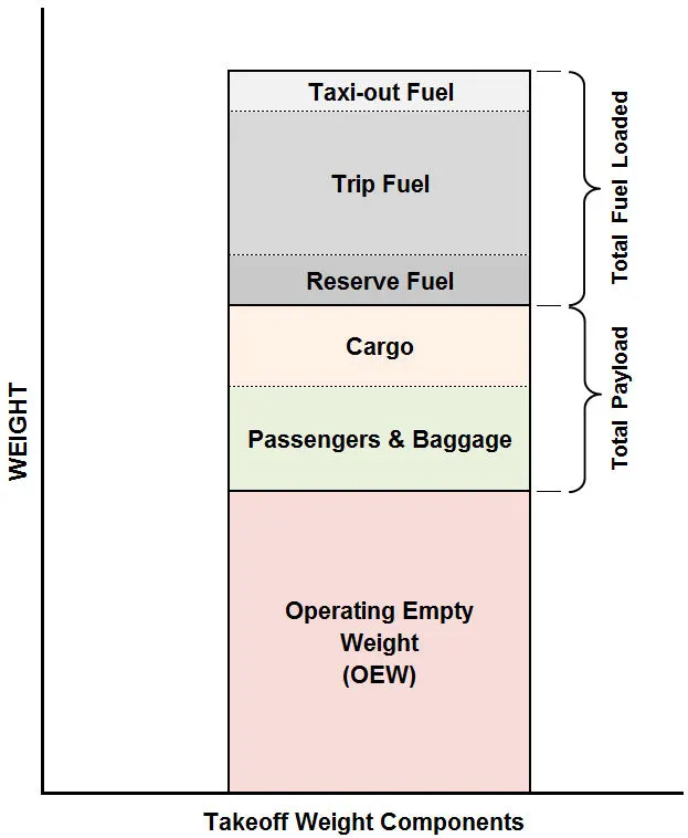
Some of the total weight oif different aircrafts are mentioned below in the table:-
| Aircraft | Empty Weight | Max Fuel Weight | Max Cargo Weight | Max Gross Takeoff Weight |
|---|---|---|---|---|
| Antanov AN-225 | 628,000 lbs 285,000 kg |
661,400 lbs 300,000 kg |
417,000 lbs 190,000 kg |
1,411,000 lbs 640,000 kg |
| Airbus A380-800 | 611,000 lbs 277,000 kg |
560,000 lbs 254,000 kg |
185,000 lbs 84,000 kg |
1,268,000 lbs 575,000 kg |
| Boeing 747-800 | 485,300 lbs 220,100 kg |
427,400 lbs 194,000 kg |
295,000 lbs 134,000 kg |
987,000 lbs 447,700 kg |
| Airbus A340-500 | 370,000 lbs 168,000 kg |
386,300 lbs 175,000 kg |
119,000 lbs 54,000 kg |
820,000 lbs 372,000 kg |
| Boeing 777-300ER | 370,000 lbs 168,000 kg | 320,800 lbs 145,500 kg | 148,000 lbs 67,100 kg |
776,000 lbs 352,000 kg |
| Boeing 787-10 | 299,000 lbs 135,500 kg | 223,500 lbs 101,500 kg |
126,300 lbs 57,300 kg | 560,000 lbs 254,000 kg |
| Boeing 737-900 | 98,500 lbs 44,700 kg |
53,100 lbs 24,000 kg |
44,600 lbs 20,200 kg |
187,000 lbs 85,000 kg |
| Airbus A320-100 | 93,900 lbs 42,600 kg |
48,700 lbs 22,100 kg |
44,000 lbs 20,000 kg |
150,000 lbs 68,000 kg |
| Embraer 190 | 63,500 lbs 28,800 kg |
28,600 lbs 13,000 kg |
28,800 lbs 13,100 kg |
106,000 lbs 48,000 kg |
| Gulfstream G650 | 54,000 lbs 24,500 kg | 48,200 lbs 21,900 kg | 6,500 lbs 3,000 kg |
100,000 lbs 45,200 kg |
| Bombardier CRJ900 | 48,160 lbs 21,850 kg | 19,600 lbs 8,900 kg | 6,075 lbs 2,760 kg | 80,500 lbs 36,500 kg |
| Bombardier Q400 | 39,300 lbs 17,800 kg |
11,700 lbs 5,300 kg |
18,700 lbs 8,500 kg |
62,000 lbs 28,000 kg |
| Learjet 75 | 13,900 lbs 6,300 kg | 6,060 lbs 2,750 kg |
2,900 lbs 1,300 kg |
21,500 lbs 9,700 kg |
| Cessna Citation CJ4 | 10,300 lbs 4,700 kg | 5,800 lbs 2,650 kg |
2,200 lbs 1,000 kg | 17,200 lbs 7,800 kg |
| Beechcraft King Air B100 | 7,100 lbs 3,200 kg | 3,200 lbs 1,450 kg |
4,150 lbs 1,900 kg |
12,000 lbs 5,400 kg |
| Diamond DA50 RG | 3,200 lbs 1,450 kg |
340 lbs 155 lbs |
1,250 lbs 560 kg |
4,400 lbs 2,000 kg |
| Beechcraft Bonanza G36 | 2,500 lbs 1,150 kg | 450 lbs 200 kg |
850 lbs 385 kg |
3,660 lbs 1,660 kg |
| Cessna 206H | 2,200 lbs 990 kg |
520 lbs 235 kg |
1,150 lbs 520 kg |
3,600 lbs 1,630 kg |
| Sirrus SR22 | 2,250 lbs 1,000 kg | 485 lbs 220 kg |
950 lbs 430 kg |
3,600 lbs 1,630 kg |
| Cessna 172R | 1,700 lbs 770 kg |
380 lbs 170 kg |
560 lbs 255 kg |
2,425 lbs 1,100 kg |
Antanov An-225 is a commercial aircraft having Maximum Gross Take off weight of around 640,000 kg.
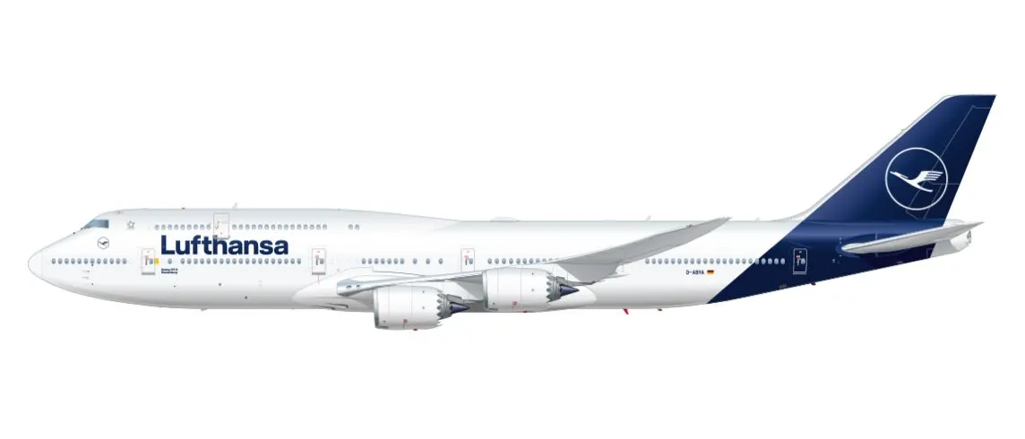
Boeing 737 is a commercial aircraft having Maximum Gross Take off weight of around 85,000 kg and having passenger cpacity of around 85 to 130.
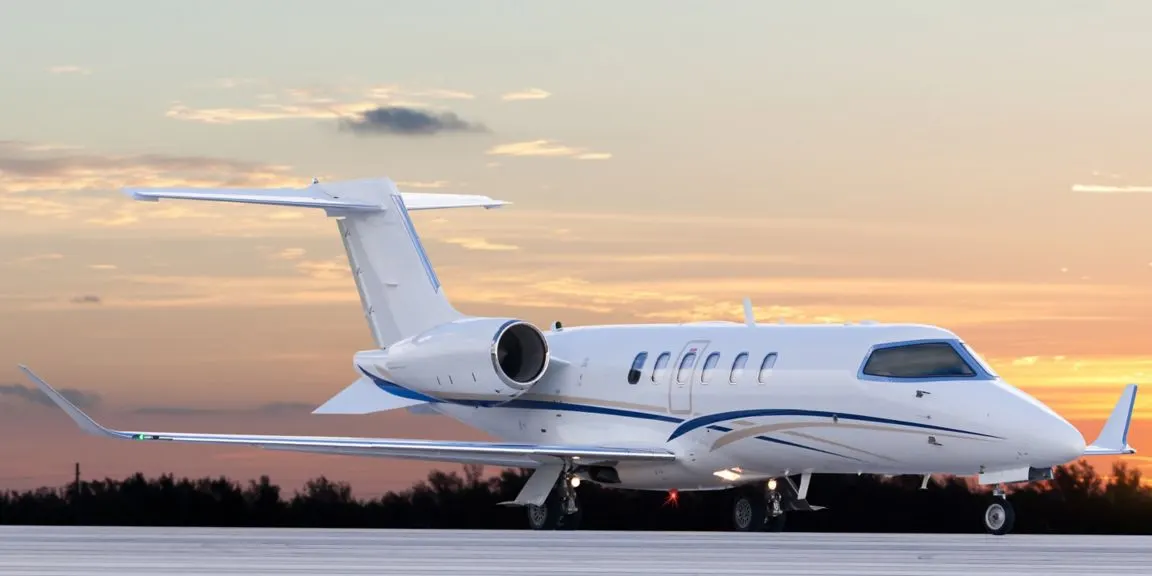
Learjet 70/75 is a mid sized bussiness jet air planes having weight around 9,700 kg.
Cirrus SR22 is a 4-5 seat composite aircraft which weight around 1630 kg.
Task-2 :- Difference between ground speed and air speed
Wind Speed:- It is the speed of the wind flowing in the enviornment with respect to the frame of reference on the ground. A positive velocity is defined when the wind flows in the direction of the the aircraft direction.
Ground Speed:- It is the speed which is relative to the horizontal movement of the aircraft with respect to the ground. For an aircraft which is moving in vertical direction only its ground speed will be zero.
Air Speed:- Air speed is the vector difference between the ground speed and wind speed. Air speed can not be computed directly from the ground speed but its a diffrence between the relative velocities of ground and wind speed.
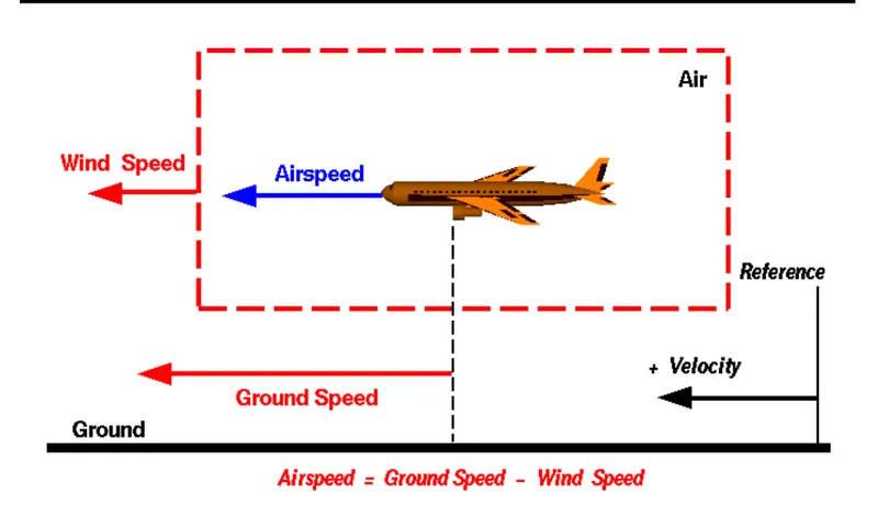
Aircraft usually operates on ground and in air so we need to study their speed difference in both ground and air. The air speed usually changes based upon the wind velocity magnitude and direction.
Let us discuss the three cases of presence of wind:-
i) when wind is Zero:- in the absence of wind the airspeed will be equal to the ground speed.
ii) when wind speed is in direction opposite of aircraft movement:- this type of wind is called headwind and in this case the air speed is greater than the ground speed as it wiil be the sum of wind and ground speed.
iii) when wind speed is in same direction of aircraft movement:- this type of wind is called tailwind and in this case the air speed is less than the ground speed as it wiil be the difference of ground and wind speed.
Task-3 :- Why is it not recommended to use aircraft engine power to move it on the ground at Airport
Aircraft move using their own engine power all the time on the airport apron and taxiways under their own power to go towards runways and after landing taxi to their assigned gate. The only time they use external assistance is to pushback from the gate. Large turbofan aircraft need help to reverse via a pushback tractor. The engines are turned on after the pushback is complete and the aircraft can move forward under it's own power.
To be accurate, some aircraft can reverse using a variable pitch prop or thrust reversing on turbofans but generally reversing is done via pushback tractors. Blasting jet reversers blows debris In the crowded gate area creating foreign object damage hazard for adjacent aircraft, gate equipment or terminal waiting area glass windows.
It is not recommended to use aircraft engine power to move it on ground at airport because of the following hazard:-
i) Loss of control can happen when the aircraft high power engine is used to run at ground in airport causing damage to the aircraft itself, other nearby planes and the ground staff.
ii) Ground Visibility is difficult for a pilot sitting in the cockpit while in comparison to the truck ot taxi triver as the sourrounding are better visible.
iii) If the aircraft engine will be used it will burn a lot of fuel and which will result in more pollution and large expense will incurred in fuels.
iv) Aircraft engine also produces a lot of noise pollution when it will run on a runway which will be create lot problem for ground staff in communicating with each other.
v) Aircraft engine when run on runway will result in higher maintenace activity.
vi) FOD (Foriegn Object Damage) could take place while running the aircraft engine in runways causing damages in airplane structure, flight controls and personnel and equipments.
Task- 4 How an aircraft is pushed to runway when its ready to take off:-
Taxiing:- Taxiing (rarely spelled taxying) is the movement of an aircraft on the ground, under its own power, in contrast to towing or pushback where the aircraft is moved by a tug. The aircraft usually moves on wheels, but the term also includes aircraft with skis or floats (for water-based travel)
An airplane uses taxiways to taxi from one place on an airports to another; for example, when moving from a hangar to the runway. The term "taxiing" is not used for the accelerating run along a runway prior to takeoff, or the decelerating run immediately after landing, which are called the takeoff roll and landing rollout, respectively.
Jet Airliners Taxiing
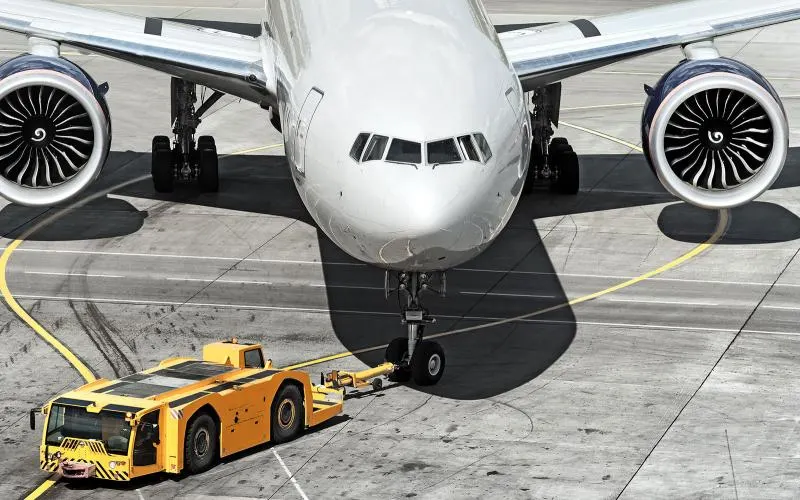
Towing:- Movement of large aircraft about the airport, flight line, and hangar is usually accomplished by towing with a tow tractor (sometimes called a “tug”). In the case of small aircraft, some moving is accomplished by hand pushing on the correct areas of the aircraft. Aircraft may also be taxied about the flight line but usually only by certain qualified personnel.
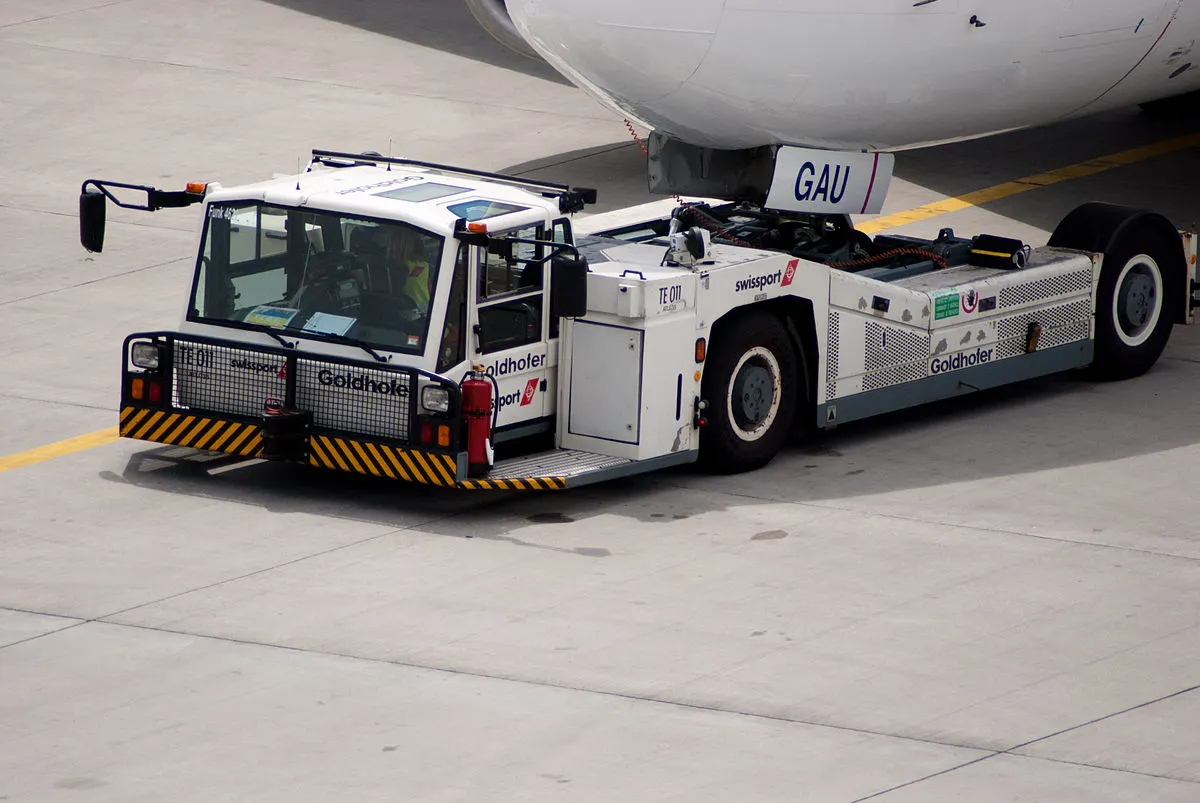
Before the aircraft to be towed is moved, a qualified person must be in the flight deck to operate the brakes in case the tow bar fails or becomes unhooked. The aircraft can then be stopped, preventing possible damage. Some tow bars are designed for towing various types of aircraft. However, other special types can be used on a particular aircraft only. Such bars are usually designed and built by the aircraft manufacturer.
When towing the aircraft, the towing vehicle speed must be reasonable, and all persons involved in the operation must be alert. When the aircraft is stopped, do not rely upon the brakes of the towing vehicle alone to stop the aircraft. The person in the flight deck must coordinate the use of the aircraft brakes with those of the towing vehicle.
Task-5 Learn about take off power, tyre design, rolling resistance, tyre pressure, brake forces when landing
i) Take Off Power:-
Takeoff is the phase of flight in which an aerospace vehicle leaves the ground and becomes airborne. For aircraft traveling vertically, this is known as liftoff. For aircraft that take off horizontally, this usually involves starting with a transition from moving along the ground on a runway.
Although the takeoff and climb is one continuous maneuver, it will be divided into three separate steps which are:-
- Takeoff roll (ground roll) is the portion of the takeoff procedure during which the airplane is accelerated from a standstill to an airspeed that provides sufficient lift for it to become airborne.
- Lift-off is when the wings are lifting the weight of the airplane off the surface. In most airplanes, this is the result of the pilot rotating the nose up to increase the angle of attack (AOA).
- The initial climb begins when the airplane leaves the surface and a climb pitch attitude has been established. Normally, it is considered complete when the airplane has reached a safe maneuvering altitude or an en route climb has been established.
T = thrust available, lbs.
D = drag, lbs.
W = weight, lbs.
γ ("gamma") = flight path inclination or angle of climb
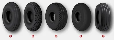
Chines:- Some tire sidewalls are mounded to form a chine. A chine is a special built-in deflector used on nose wheels of certain aircraft, usually those with fuselage mounted engines. The chine diverts runway water to the side and away from the intake of the engines.
iii) Rolling Reistance:- The force that resists the motion of a body rolling on a surface is called the rolling resistance or the rolling friction
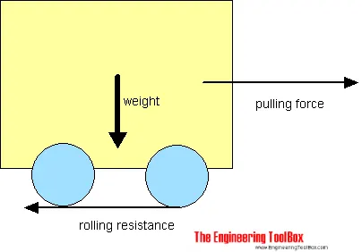
The rolling resistance can be expressed by the generic equation
Fr = c W --------------------------------------(a)
where,
Fr = rolling resistance or rolling friction (N, lbf)
c = rolling resistance coefficient - dimensionless (coefficient of rolling friction - CRF)
Also, W = m ag = normal force or weight of the body (N, lbf)----------(b)
m = mass of body (kg, lb)
ag = acceleration or gravity (9.81 m/s2, 32.174 ft/s2)
Some typical Rooling Resistance Coefficient values are:-
| Rolling Resistance Coefficient | Applications | |
|---|---|---|
| c | cl (mm) | |
| 0.001 - 0.002 | 0.5 | railroad steel wheels on steel rails |
| 0.001 | bicycle tire on wooden track | |
| 0.002 - 0.005 | low resistance tubeless tires | |
| 0.002 | bicycle tire on concrete | |
| 0.004 | bicycle tire on asphalt road | |
| 0.005 | dirty tram rails | |
| 0.006 - 0.01 | truck tire on asphalt | |
| 0.008 | bicycle tire on rough paved road | |
| 0.01 - 0.015 | ordinary car tires on concrete, new asphalt, cobbles small new | |
| 0.02 | car tires on tar or asphalt | |
| 0.02 | car tires on gravel - rolled new | |
| 0.03 | car tires on cobbles - large worn | |
| 0.04 - 0.08 | car tire on solid sand, gravel loose worn, soil medium hard | |
| 0.2 - 0.4 | car tire on loose sand | |
Tyre Pressure:-
Aircrafts tyre generally operate at high pressure nera about 200 psi (14 bar or 1400 KPa) for airliners and can be high for bussiness jets. The main landing gear on the concorde is typically inflated upto 232 psi (16 bar) while its tail bumper gear tires were as high as 294 psi (20.3 bar).
Test of airliner aircraft tires have shown that they are able to sustain air pressure of maximum upto 800 psi (55bar or 5500 KPa) before bursting. During the test the tires have to be filled with waters to prevent the test room to be blown out by the energy which is released during bursting of tires.
Aircraft tires are usually inflated with nitrogen to minimize expansion and contraction from extreme changes in ambient temperature and pressure eperienced during flight. Dry nitogen expands same at the same rate as the dry atmospheric gases (normal air is 80% nitrogen), but common compressed air sources may contain moistures, which may increase the expansion rate with temprtaure.
v) Brake forces when Landing:-
The brakes used in aircrafts while landing are as follows:-
a) Aircraft Disc Brakes:- It is used to brake the wheels while touching the grounds. These brakes ae applied hydraulically or pneumatically. In most modern aircraft they are activated by the top section of the rudder pedals (toe brakes). In some old aircraft the bottom section is used instead (heel brake). some of the aircraft are provided with levers. Most of the aircrafts are capable of diffrential braking.
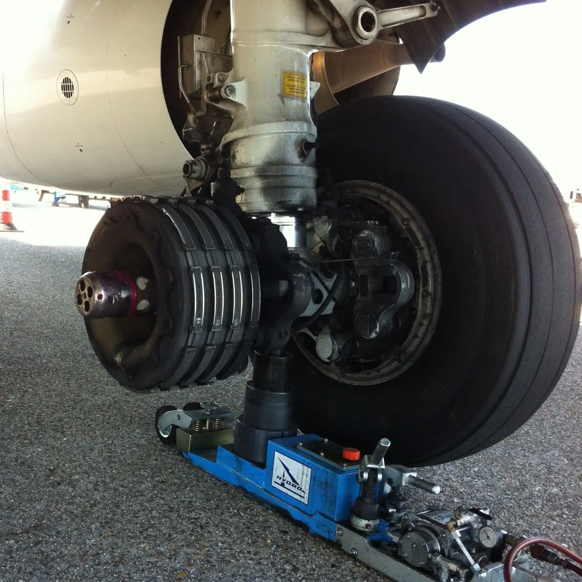
b)Thrust Reversers:- It is provided in the jet aircrafts to provide the significant way of increasing the rate of deacceleration during the inital stage of landing roll or rejected takeoff from a high speed.Use of reverse thrust on low wing aircraft with mounted engines must be limited to the time when the aircraft is in the active runway.
c)Air Brakes:- Air brake or speed brakes are used to cause the aircraft slow down more rapidly when they are developed. They produces a drag which require a high power setting, these setting are much more responsive and rapid and thus making power and glide scope correction on approach more rapidly with speed brakes deployed.
d)Large Drouge Parachutes:- It is a parachutes designed for deployement from a rapidly moving object. It is used for various purposes such as to decrese the speed, to provide control and stability or as a pilot parachutes to deploy a larger parachute.
Part - B
Task -6 A). With necessary assumptions, calculate the force and power required to push / pull an aircraft by a towing vehicle.
For this task i have considered Boeing 747-800
Total mass of aircraft inculing payload(M) :- 447,700 kg
Towing Vehicle:- Volkswagen Touareg
Mass of Towing Vehicel(m)- 2135 kg
Gravity- 9.81 m/s^2
Urr= 0.01 (on asphalt )
i) Rolling Resistance Force Calculation for Aircraft:-
Frra= M*g*Urr
Frr= 447700*9.81*0.01 = 43.92 KN
ii) Rolling Resistance Force Calculation for Towing Vehicle:-
Frrt= m*g*Urr
Frr= 2135*9.81*0.01 = 0.209 KN
Total Rolling Resistance Force= Frra+Frrt= 44.12 KN
iii) Aerodynamic Force Calulation:-
Specific Air Density (ρ)- 1.125 kg/m^3
Drag Coefficient (Cd)= 0.025
Frontal area of Towing vehicle(A) - 3.5 m^2 (1.717*1.984, height and width respectively)
Velocity of towing vehicle (v))- 3 m/s
Aerodynamic force (Fad)= 1/2*ρ*Cd*A*(v^2)
Fad= 0.0004 KN
Also the runways are usually the flat surfaces so the uphill force will be 0.
Now the total tractive force required by the towing vehicle will be
Ft= Frra+Frrt+Fad (since the aerodynamic force is very less so we can neglect it)
Ft= 44.12 KN
Also we know that Power Calculation can be given by:-
Pm= Ft*v
Pm= 44.12*3 = 132.38 kW.
B) A simulink model is made by the use of constant, square, product, sum and display block to generate the required force and power.
The model is shown below:-
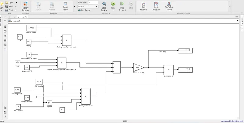
From the above simulink model we get to know that the motor Power which is required is of 132.38 kW
Task- 7. A. Design an electric powertrain with type of motor, it’s power rating, and energy requirement to fulfill aircraft towing application in Simulink. Estimate the duty cycle range to control the aircraft speed from zero to highest. Make all required assumptions. Prepare a table of assumed parameters. Draw a block diagram of powertrain.
Powertrain Block Diagram:-
Duty Cycle calculation:-
As we have calculated the motor power requirement for the towing vehicle we can now select the motor based upon that value. I have selected HPDM 250 motor for the same
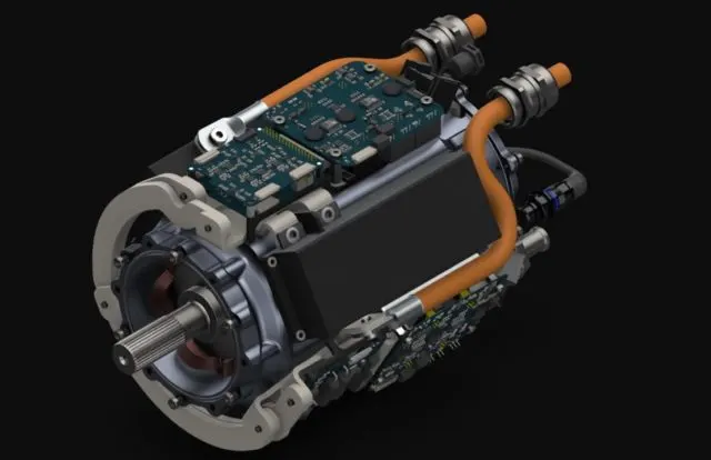
HPDM 250 electric aircraft motor
Technical detail of the motor are as follows:-
It is clear from the datasheet that 95 Nm of cont. torque and 120 Nm of Peak Torque can be provided from the above motor, Motor input Voltage can be considered as 440 V and its rpm can vary from 0 to 20000.
Efficiency of the motor is given as- 94.5 %
also considering 10% loss in the power electronic devices we can calculate the duty cycle required for the motor
Battery Voltage is considered as 500V
So Duty Cycle= Vout/Vin
Vin= 500 V
Vout= 440*0.95*0.9= 376.2 V (where 0.95 is motor eff. and 0.9 is the correction factor)
Duty Cycle (d)= 376.2/500= 75.24%
Assumed Parameter for the motor power calculation:-
| Mass Of Aircraft (kg) | 447700 |
| Gravity (m/s^2) | 9.81 |
| Rolling Resistance Coefficient for asphalt | 0.01 |
| Mass of Volkswagen Touareg (kg) | 2135 |
| Specific Air Density (kg/m^3) | 1.125 |
| Air Drag Coefficient for Towing Vehicle | 0.025 |
| Height of Volkswagen Touareg (m) | 1.71 |
| Width of Volkswagen Touareg (m) | 1.984 |
| Frontal Area (m^2) | 3.39264 |
| Velocity of towing vehicle (m/s) | 3 |
| Battery Voltage (V) | 500 |
| Motor Input Voltage (V) | 415 |
| Motor Eff. | 0.95 |
| Correction factor | 0.9 |
| Uphill gradient | 0 |
Simulink Model:-
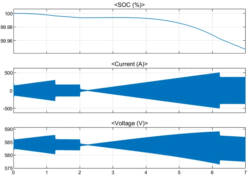
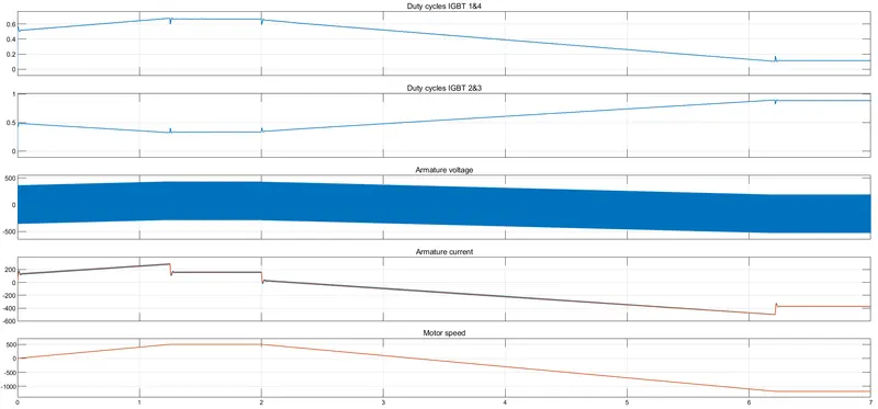
Here I have used 4 quadrant Chopper Dc drive and battery having Nominal voltage 500V and rated Capacity 400 Ah.
Speed refrence is given from the step signal which states that duruing first 2 sec the motor speed reference is given as 500 rpm and fior the rest of the time speed reference is changed to -1185. The model look like this:-
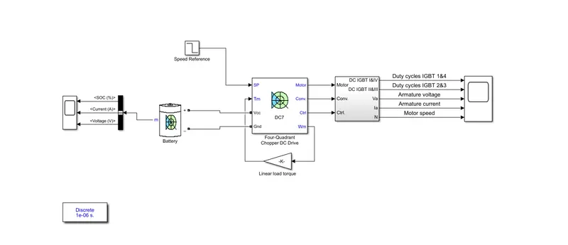
The model is ri=un for simulation time of 7 sec and the result are as follows:-
Results:-
Baterry SOC, Current and Voltage are shown below:-
IGBT duty cycles, Armature Voltage, armature Current and Motor speed in rpm of Dc motor is shown below:-
Excel sheet:-
| Rolling Resistnace Force Calculation | |
| Aircraft Rolling Resistance Force | |
| Mass Of Aircraft (kg) | 447700 |
| Gravity (m/s^2) | 9.81 |
| Rolling Resistance Coefficient for asphalt | 0.01 |
| Rolling Reistance Force for Aircraft (N) | 43919.37 |
| Towing Vehicle Rolling Reistance Force | |
| Mass of Volkswagen Touareg (kg) | 2135 |
| Gravity (m/s^2) | 9.81 |
| Rolling Resistance Coefficient for asphalt | 0.01 |
| Rolling Reistance Force for Towing Vehicle (N) | 209.4435 |
| Total Rolling Resistance Force (KN) | 44.1288135 |
| Aerodynamic Force Calculation | |
| Specific Air Density (kg/m^3) | 1.125 |
| Air Drag Coefficient for Towing Vehicle | 0.025 |
| Height of Volkswagen Touareg (m) | 1.71 |
| Width of Volkswagen Touareg (m) | 1.984 |
| Frontal Area (m^2) | 3.39264 |
| Velocity of towing vehicle (km/hr) | 10.8 |
| Velocity of towing vehicle (m/s) | 3 |
| Aerodynamic Force (N) | 0.429381 |
| Aerodynamic Force (KN) | 0.000429381 |
| Uphill Force will be zero as the runway are made flat in surface | |
| Total Force Required (Frr) (neglecting aerodrag force since it is too small) (KN) | 44.1288135 |
| Tractive Power Required (kW) | 132.3864405 |