Final Project: Electric Rickshaw modelling
Project:-
Create a detailed MATLAB model of an electric rickshaw (three wheel passenger vehicle) as per details below:
Rear wheels driven by PM brushed type motor
Assume efficiency points of motor controller and motor
Make an excel sheet of all input and assumed data
Results: For any three standard driving cycles show energy consumption, temperature rise of motor and controller for 100 km constant speed driving at 45 kmph.
Project URL:- https://drive.google.com/drive/folders/1ttH_Y8YAXqAWXlu5azjCAb713o9oRiSA?usp=sharing
Electric rickshaws (also known as electric tuk-tuks or e-rickshaws or toto or e-tricycles) have been becoming more popular in some cities since 2008 as an alternative to auto rickshaw and pulled rickshaws because of their low fuel cost, and less human effort compared to pulled rickshaws. They are being widely accepted as an alternative to petrol/CNG/Diesel auto rickshaws. They are three-wheelers powered by an Electric Motor ranging from 650 to 1400 Watts. They are mostly manufactured in India and China. Battery-run rickshaws could be a low-emitter complementary transport for the low-income people, who suffer most from a lack of transport facility, if introduced in a systematic manner according to experts.
E- rickshaws have a M.S(Mild Steel) tubular Chassis, consisting of three wheels with a diffrential at the rear wheels. The motor is brushless DC motor manufactured mostly in India and China. The electrical system used in Indian version is 48V and Bangladesh is 60V. The body design from most popular Chinese version is of very thin iron or aluminum sheets. Vehicles made in fiber are also popular because of their strength and durability, resulting in low maintenance, especially in India. Body design is varied from load carriers, passenger vehicles with no roof, to full body with windshield for drivers comfort. It consist of a controller unit.They are sold on the basis of voltage supplied and current output, also the number of MOSFET (metal oxide field effect transistors) used. The battery used is mostly Lead Acid battery with life of 6–12 months.
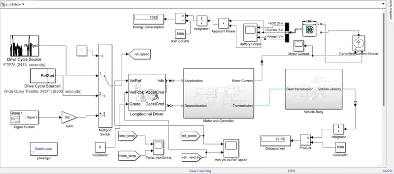
Block Used :- Drive Cycle Source, Signal Builder, Gain, Powergui, Constant, Multiport Switch, Longitudnal driver, Go to and from block, Scope, Display, Product, Integrator, Constant Current Source, Battery, Constant Voltage Source, Controllled Voltage PWM, H Bridge, DC Motor, Electrical reference, Rotational reference, Solver Configuration, Current Sensor, PS- Simulink converter, Simulink-PS converter, Temperature sensor, Simple gear, Inertia, Tire (magic formula), Vehicle Body, PS constant, PS terminator.
Assumed Data:-
| S. No. | Parameters | Input Data values |
| 1 | Longitudinal driver | |
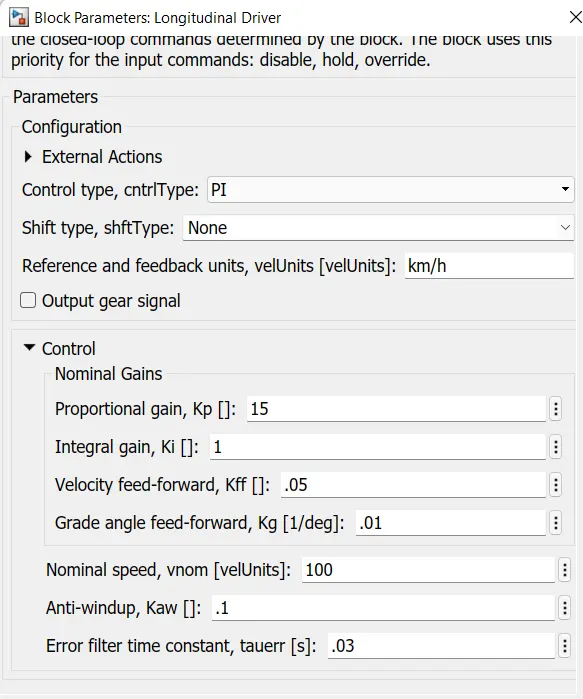
| 1.a | Control Type | PI |
| 1.b | Shift type | None |
| 2 | Battery | |
| 2.a | Type | Li-ion |
| 2.a.1 | Nominal voltage | 48 V |
| 2.a.2 | Battery capacity | 150 Ah |
| 2.a.3 | Initial SOC | 100% |
| 2.a.4 | Battery Response Time | 30 sec |
| 3 | Motor and Controller Subsytem | |
| 3.a | Controlled PWM Voltage Source | |
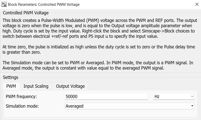
| 3.a.1 | PWM Freq. | 50000 Hz |
| 3.a.2 | Simulation Mode | Average |
| 3.a.3 | Input Voltage for 0% duty cycle | 0 V |
| 3.a.4 | Input Voltage for 100% duty cycle | 2 V |
| 3.a.5 | Output Voltage Amplitude | 48 V |
| 3.b | H Bridge | |
| 3.b.1 | Simulation Mode | Average |
| 3.b.2 | Load Current characterstic | Smoothed |
| 3.b.3 | Enable Threshold Voltage | 2.5 V |
| 3.b.4 | PWM Signal Amplitude | 5 V |
| 3.b.5 | Reverse Threshold Voltage | 2.5 V |
| 3.b.6 | Braking Threshold Voltage | 2.5 V |
| 3.b.7 | Output Voltage Amplitude | 48 V |
| 3.b.8 | Thermal Mass | 50000 J/K |
| 3.b.9 | Initial Temperature | 298.15 K |
| 3.c | DC Motor | |
| 3.c.1 | Model paramterization | By rated load & speed |
| 3.c.2 | Armature Inductance | 6e-6 H |
| 3.c.3 | No- Load Speed | 8500 rpm |
| 3.c.4 | Rated Speed | 8000 rpm |
| 3.c.5 | Rated Load ( Mech. Power) | 1.5 Kw |
| 3.c.6 | Rated Suuply DC voltage | 48 V |
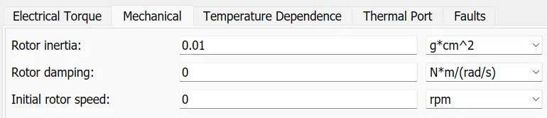
| 3.c.7 | Rotor Inertia | 0.01 g*cm^2 |
| 3.c.8 | Resistance Temperature Coefficient | 3.93e-3 1/K |
| 3.c.9 | Measurement Temperature | 298 K |
| 3.c.10 | Thermal mass | 50000 J/K |
| 3.c.11 | Initial temperature | 298 K |
| 4 | Vehicle Body Subsystem | |
| 4.a | Gearbox | |
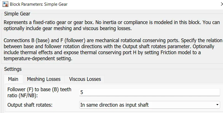
| Follower to base ratio | 5 | |
| Output shaft rotates | same as input shaft dir. | |
| 4.b | Vehicle Body | |
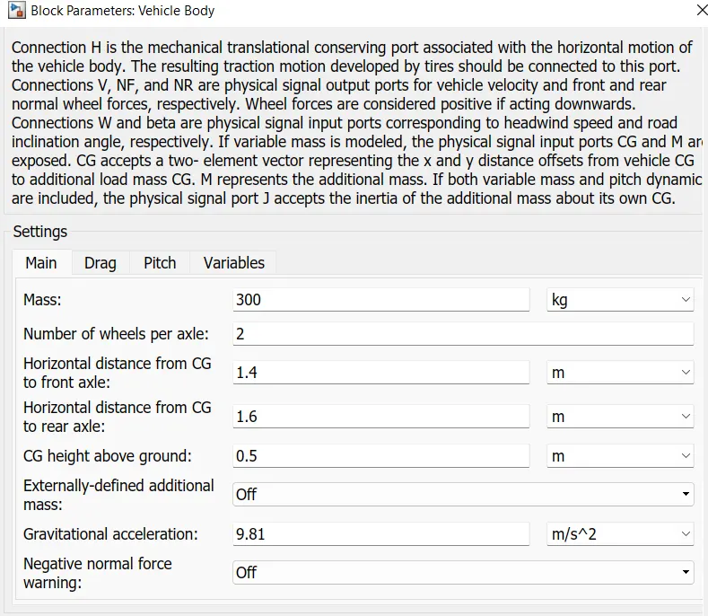
| 4.b.1 | Vehicle Mass | 300 Kg |
| 4.b.2 | No. of wheel per axle | 2 |
| 4.b.3 | Horizontal distance from CG to front axle | 1.4 mtr |
| 4.b.4 | Horizontal distance from CG to rear axle | 1.6 mtr |
| 4.b.5 | CG height above ground | 0.5 mtr |
| 4.b.6 | Gravitational acceleration | 9.81 m/sec^2 |
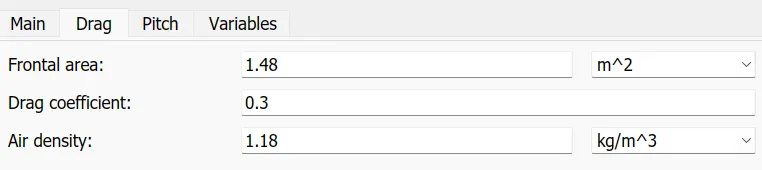
| 4.b.7 | Frontal Area | 1.48 m^2 |
| 4.b.8 | Drag coefficient | 0.3 |
| 4.b.9 | Air Density | 1.18 kg/m^3 |
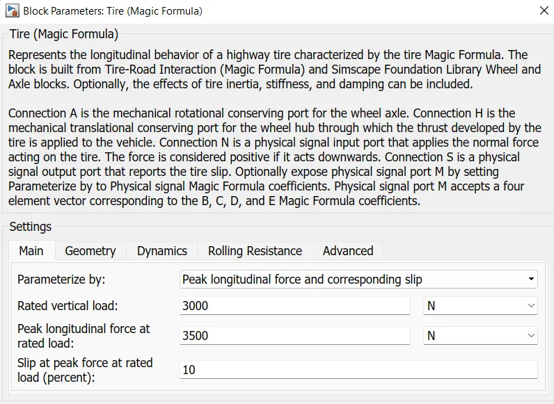
| 4.c | Tire ( Magic formula) | |
| 4.c.1 | Parametrized By | Peak longitudinal force |
| 4.c.2 | Peak vertical load | 3000 N |
| 4.c.3 | Peak longitudinal force at rated load | 3500 N |
| 4.c.4 | Slip at peak load at rated load | 10% |
| 4.c.5 | Rolling radius | 0.254 mtr |
| 4.c.6 | Rolling resistance | Off |
Block Diagram:-
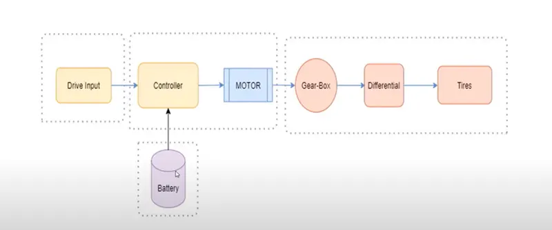
Electric Rickshaw have a forward and reverse mode. When we press on the accelerator pedal the following things happen:
- Power is converted from the DC battery for the electric motor
- The accelerator pedal sends a signal to the controller which adjusts the vehicle's speed by changing the frequency of the AC power from the inverter to the motor
- The motor connects and turns the wheels through a cog
- When the brakes are pressed or the rickshaw is deaccelerating, the motor becomes an alternator and produces power, which is sent back to the battery.
From the Block diagram we understood that an E rickshaw must have these main components:-
i) Drive Cycle
ii) Battery
iii) Driver Configuration
iv) Power Converters and Motor
v) Gear and Vehicle Dynamics.
So let us discuss each and every subsystem one by one.
i) Drive Cycle:- It is a set of data points which represent the speed of vehicle versus the time. They are used in propulsion system simulation to predict performance of IC engine, transmissions, Electric Drive suystem, batteries, fuel cell system etc. Here in this project we will be using 3 different drive cycle to test the performance our Modelled e rickshaw and these are:-
a) FTP-75 (2474 Cycle) :- Fedral Test Procedure 75 drive cycle is used to estimate the range distance travelled by an Electric Vehicle in a single charge.
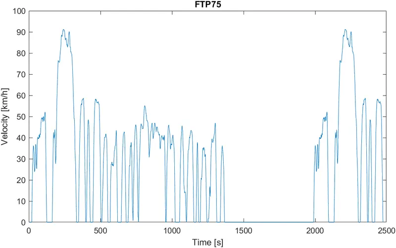
Here we run the simulation for 2474 second.
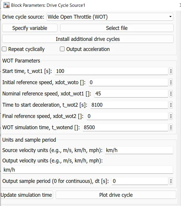
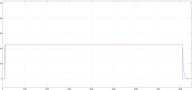
b) WOT (Wide Open Throttle) :- It is used to generate the user specific or longitudnal drive cycle. The block output is the vehcile longitudnal speed. Here in my case I have declared parameter of WOT as :-
The plot of speed vs time is as shown below:-
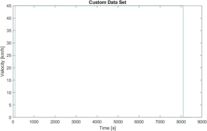
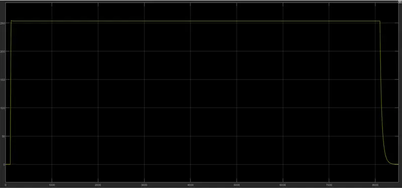
For the First 100 sec vehicle is at standstill after that a constant speed of 45 kmph is applied for total 8100 sec and then vehicle is deaccelerated to rest. Total simulation time is 8500 sec.
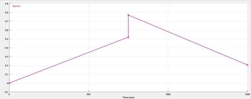
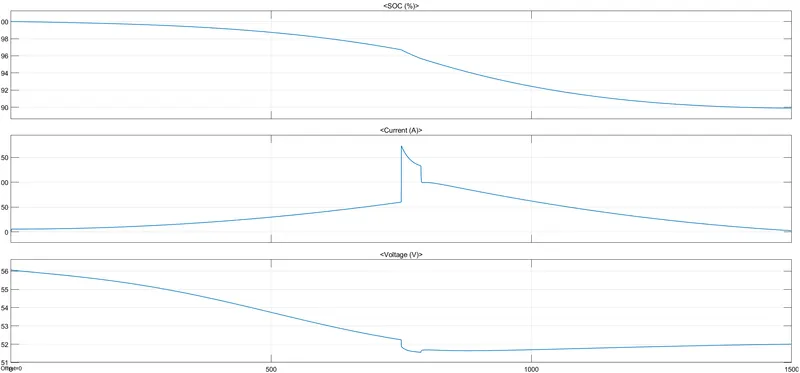
c) Signal builder:- It is also a user specific block with which user can test the vehicle performance at any desired speed. In my case the vehicle at start with constant accelration upto 750 aec then a sudden step of 0.8 is provided and after that the vehicle is retarded to 0.2 after total 1500 sec. Also a gain of 100 is provided as the values in y axis are in decimal and the speed is to be in kmph so gain is provided.
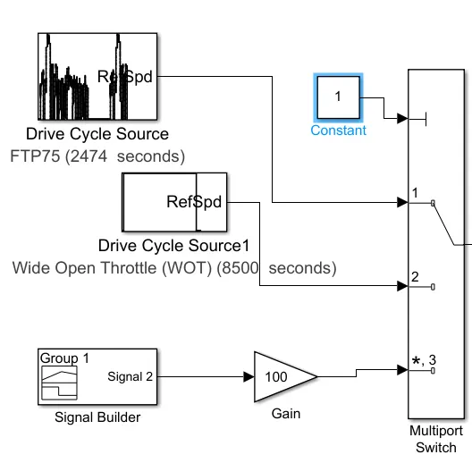
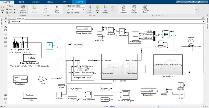
Now using this three drive cycle i have used a Multiport switch as to turn on a Single driving source at a time.
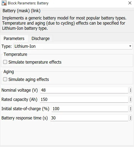
ii) Battery:- A battery package is used which is Lithium Ion Battery of 48 V and 150 Ah. The output of the battery is SOC, currenta and voltage. A controlled current source is used to charge and discharge the battery. The input of the Controlled current source is from the Power converter block through a PS- simulink converter.
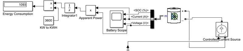
Th temperature effect are not simulated for the battery.
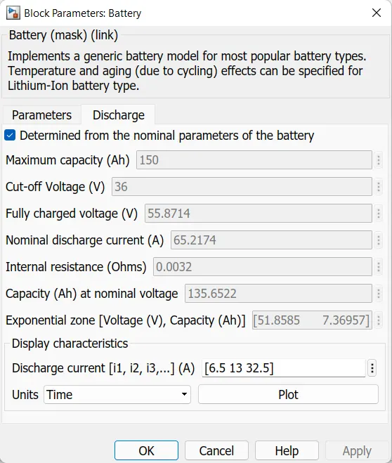
Block parameter of the Battery are as follows:-
iii) Driver Configuration:- Here i have used Longitudnal Driver.
Longitudinal driver:- It is a longitudinal speed tracking controller. Based on the reference and the actual vehicle velocities, this block generates acceleration and braking commands accordingly in the form of 0 and 1.
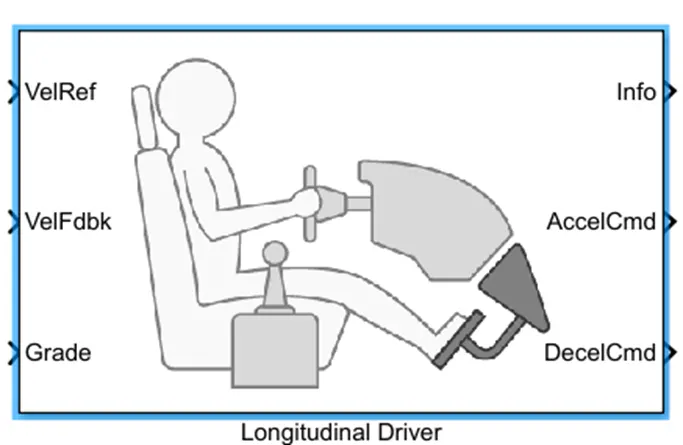
It has following 3 input port which are on the left and 3 output ports on the right side of the block.
VelRef- ( Velocity reference)- Reference speed is provided gthrough this input port.
VelFdbk- ( Velocity Feedback)- Feedback of vehicle actual speed is provided through this input port.
Grade- This port provide the gradability or inclination angle for the surface on ehich the vehicle is running.
Info- This is the outport port through which bus signal which consist of block calculation eg acc./deacc. command diffrence between reference and vehicle speed.
Accel cmd (Acceleration Command):- This outport provide the acc command in the form of 0 and 1 and in this model this command is provided to the controlled voltage source of Acceleration
Decel Cmd (Deacceleration Command)- This outport provide the deacc command in the form of 0 and 1 and in this model this command is provided to the controlled voltage source of Brake.
Block parameter of the Longitudinal driver are as follows:-
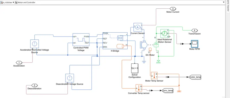
iv) Motor and Controller:- This subsystem contain power electronic converter and Dc motor block. The controller consist of power converter devices like Controlled Voltage Source, Controlled PWM Voltage and H bridge. DC motor have mechanical and electrical parts. Details of these block are as follows:-
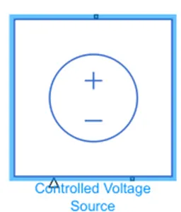
a) Controlled Voltage Source:- It is a souce which activate when the signal applied to it get high and the volatge is applied across the +ve terminal of the Source and in this model i have used two voltage sources one for acceleration and another for braking.
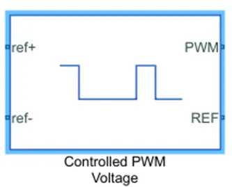
b) Controlled PWM Voltage Source:- It is used to provide controlled Pulse widdth modulated signals to the H bridge. The block will provide output from the PWM and reference is used as ground by connecting it through electrical reference. The input of the PWM block is +ve and -ve reference. +ve reference is provided from the Accelerated Control Voltage Source and -ve of the ref is connected to the Electrical reference.
Parameter of the block are as follows:-
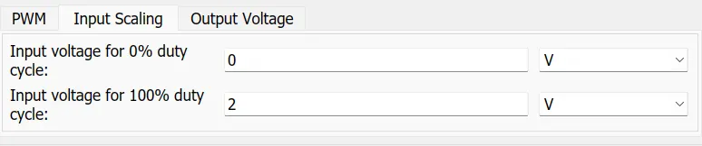

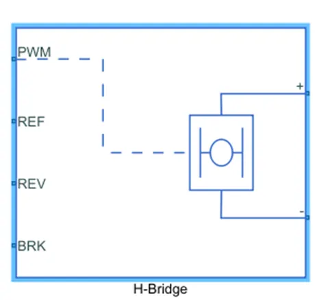
c) H Bridge:- H bridge is the power converter used here as it convert the required signal in the form of desired output and the output is applied to the Dc motor. It has two part one is left and other is right part. Right part is connected to the positive and negative of dc motor. and The left part consist of following parameters:-
PWM-(Pulse width Modulation) will provide the voltage pulses to the H bridge either in PWM or average form. and is applied input from PWM of the Controlled PWM Voltage Source
Ref- (Reference)- Electrical Reference is provided to this port.
Rev- (Reverse)- Electrical reference is provided to this port.
Brk- (brake)- It is provided signal from the Brake controlled Voltage source
Block parameters are as follows:-
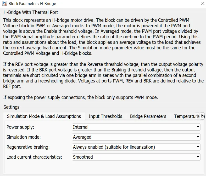
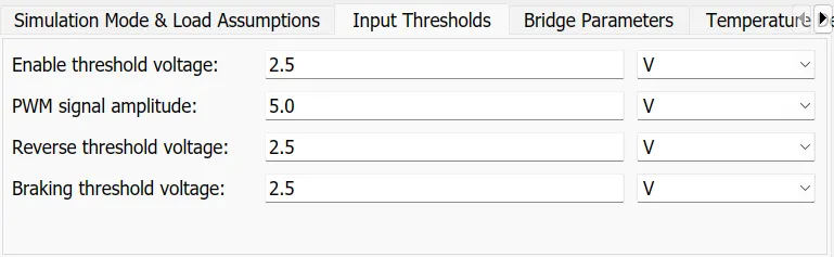
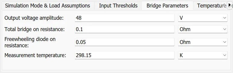
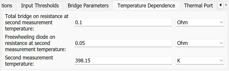
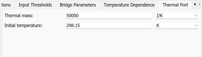
The thermal port is enable by right clicking over the H bridge and then seleclting the following blocks:-

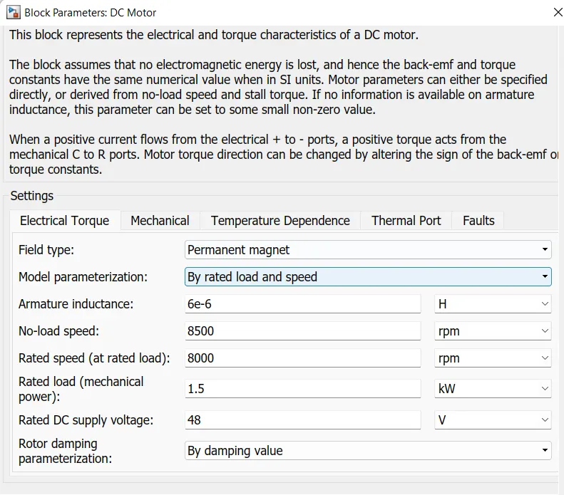
d) DC Motor:- Simple Permanent Magnet Brush type Dc motor is selected as they are easy to model because of there less complex behaviour as in comparison with induction motor or BLDC motor.
This motor has two part one is electrical on the left and other is mechanical part on the right. Mechanicla part is having two connection R ( Rotor) and C (Case). C part is connected to the rotational reference and R is connected to the Base of Simple gear of the vehicle body subsystem. Electrical part comprises of positive and negative terminals. The positive part is connected to the H brige positive and negative terminal ios connected to the negative of H bridge along with the electrical reference.
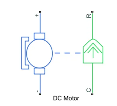
Parameter of the DC motor are:-



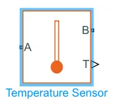
e) Temperature sensor:- It is a block which senses the temperature difference between two points without drawing any heat. The physical signal port T reports the temperature difference across the sensor. The measurement is positive when the temperature at port A is greater than the temperature at port B.
The subsystem of Motor and Controller can be viewed as:-
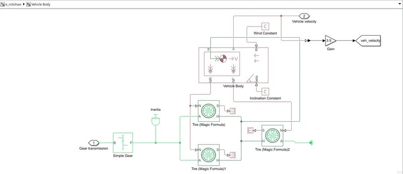
v) Vehicle Body:- It contain major block such as Simple Gear, Vehicle Body and Tire ( magic formula). It focuses more on the dynamics of the vehicle like the road condition, sourrounding condition and the load on the wheels etc.
a)Simple Gear :- It is used for the transmission system of the vehicle. I have used simple gear to simplify the transmission related parameter. It has B which is bse and it is getting input from the motor shaft and follower which is reducing the speed of motor and is coupled to the axle of the rear wheels.
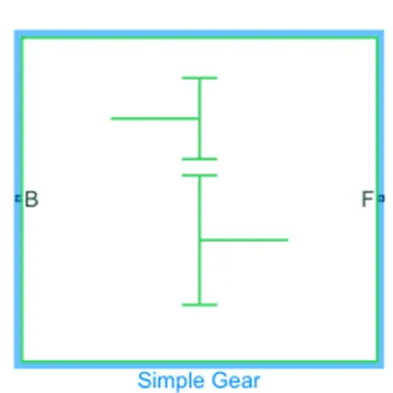
Parameter of Simple Gear:-


b)Vehicle Body:- We can get the vehicle body block in Simulink as in the image shown below
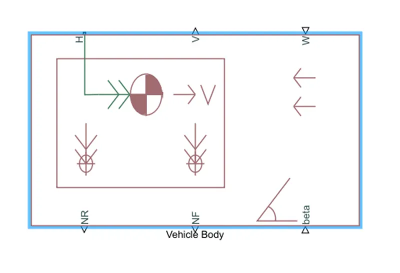
As from the image it was seen that the vehicle body block contain six main sub-parts such as:-
H (Hub) - It is used to connect the hub of the wheels to the main body of the vehicle
V (Velocity)- It is an output port and used to tell us that at what speed our vehicle is running i.e. the actual speed of the vehicle is known through this port.
W (Wind Velocity) - It is an input port by which we can consider the impact of wind acting on the vehicle.
NR (Normal Rear Force)- It gives the signal output for normal force acting on the rear wheel of the vehicle
NF (Normal Front Force)- It gives the signal output for normal force acting on the front wheel of the vehicle
Beta (Angle of Inclination)- It is used to consider the hill climbing force acting on the vehicle.
Parmeter of Vehicle body are as follows:-


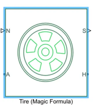
C)Tire (Magic Formula):- Here i have used Magic formula tire in this model, as it allow us to model the tire behaviour on highways. It also allow us to consider tire inertia, stiffness which can be more accurate for real world condition. the magic tire block is shown below:-
Parameter of Tire block:-




The Vehicle Body subsytem look like:-'
Results:-
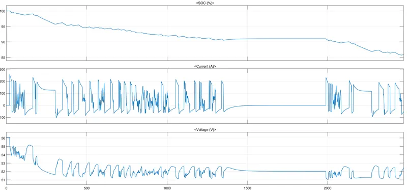
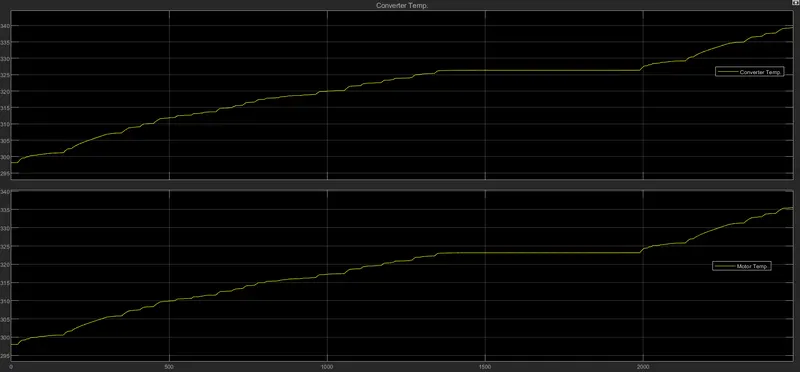
i) For FTP 75 drive cycle :- The simulation run time foe this drive cycle is about 2474 seconds. The distance travelled by the vehicle is about 22.13 kmph and the energy consumption is about 1093 Kwh
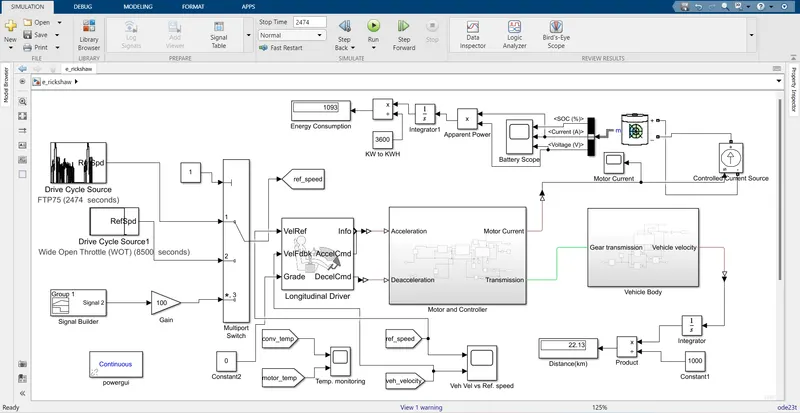
The battery SOC is intially at 100% and it drop to around 85% after completion of one FTP 75 drive cycle.
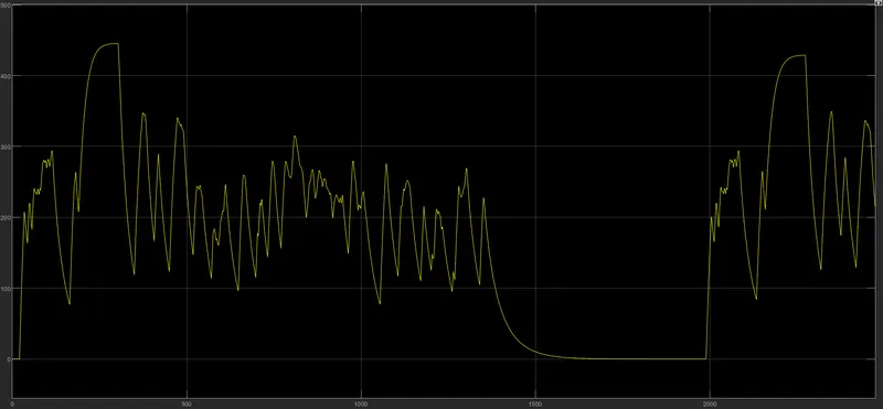
Motor RPM:-
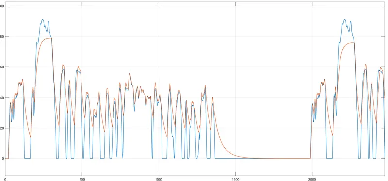
Reference Vs Actual Vehicle speed:- Here we can see that the vehicle almost follow the drive cycle but it does not reaches the maximux value due to the motor speed constraint.
Converter and Motor Temperature are also under the range of 335-340 Kelvin.
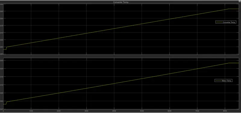
ii) For Wide Open throttle Condition:- The simulation run time for this drive cycle is 8500 sec. Here we can observe that the vehicle has travelled the distance of 103 km ans Energy consumption is about 4690 KWH.
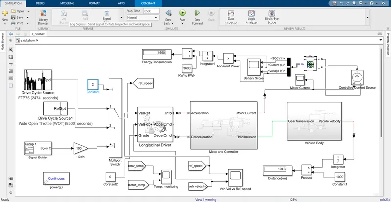
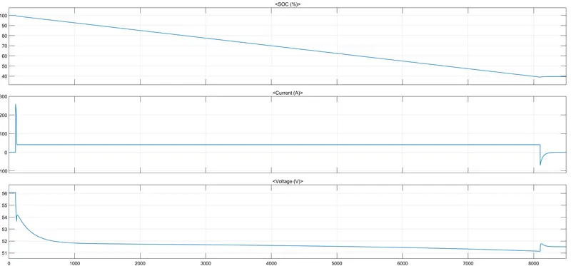
Battery SOC is in the range of 40% after running for 8500 sec.
Motor RPM:-
Reference Vs Actual Vehicle speed:- The actual velocity of vehicle is following the refrence velocity.
Converter and Motor Temperature are also under the range of 322-330 Kelvin.
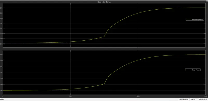
iii) For Signal Builder Block:- The simulation run time for this drive cycle is 1500 sec. Here we can observe that the vehicle has travelled the distance of 15.95 km ans Energy consumption is about 792 KWH.
Battery SOC is in the range of 90% after running for 1500 sec.
Motor RPM:-
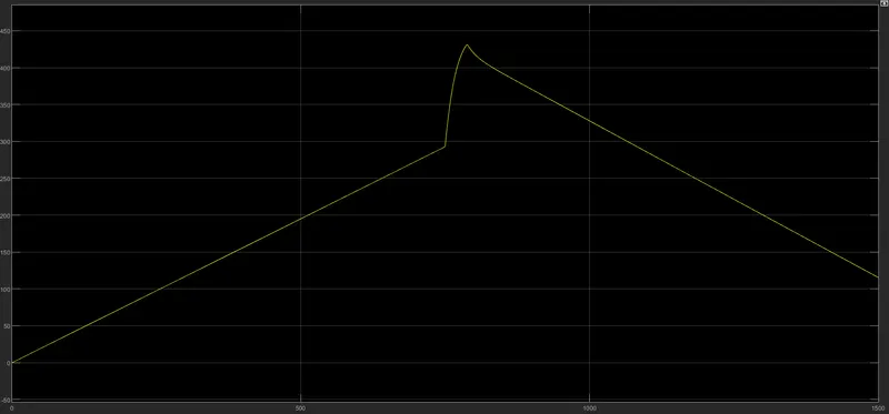
Reference Vs Actual Vehicle speed:- The actual velocity of vehicle is following the reference velocity.
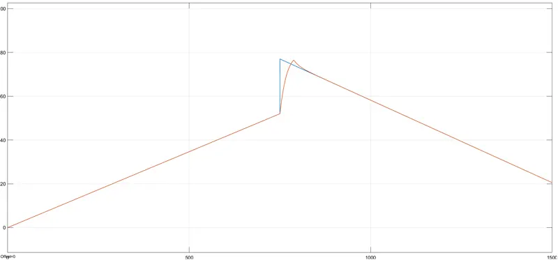
Converter and Motor Temperature are also under the range of 303-305 Kelvin.