Week - 4
Task 1:- Implementing a control logic of Washing machine and make a model according to the condition mentioned in the task.
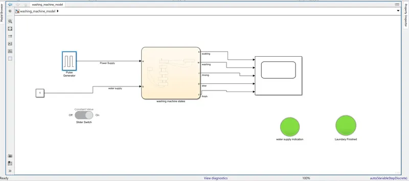
Block Used:- Pulse Generator, Constant, Slider Switch, Chart Block, Scope and Lamp
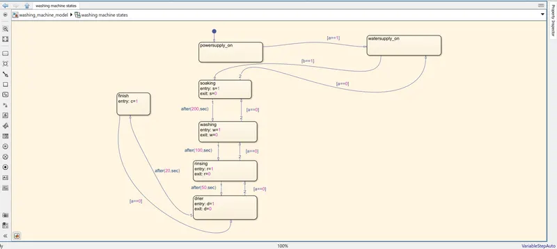
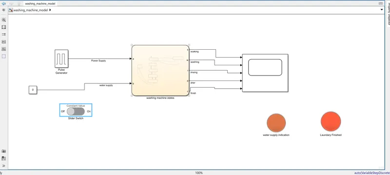
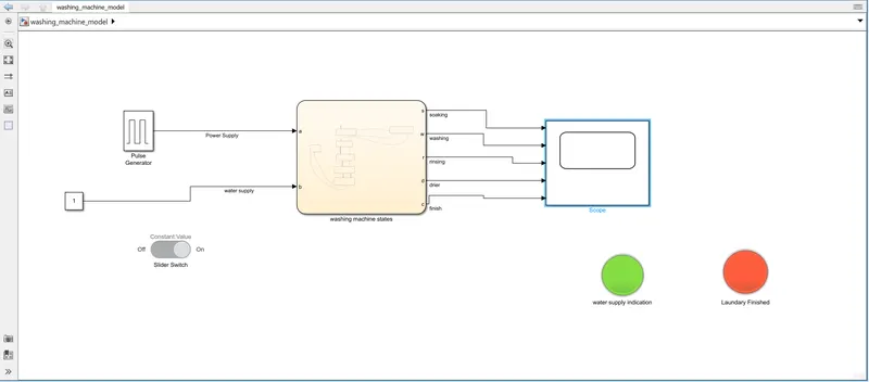
Working of the model:- As per the task, the machine is to be opearted on two basic condition one is availability of power supply and other is availability of water supply. So I have provided an electrical supply through apulse generator which is having a period of 500 sec ( approx. time of laundary completion) and i have given pulse width time duration of 80% i.e. 400 sec. and for water supply i have used a constant 1 which is connected to a slider switch having position On/Off. Now these two condition will be the input of the washing machine. In any case any of the two supplies fail the process of cloth washing will not be completed. Now i created a chart with name washing machine states and taken these power and water supply as input a and b respectively. And we have four different states for soaking, washing, rinsing and drying so we have considered these states as output (s, w, r and d respectively) along with one more output that if the process of washing cloth is completed or not by variable c. Now we have given the condition in the states such as to run the machine when the basic input are ok then I have provided input such that while entering a state entry is given as 1 and while exiting a state value becomes 0 and a proper delay is provided with using a term after for the machine to change its state from one condition to another. Also arrangement has been made such that in case the power supply fails then, the machine will not reach to its outcome i.e. laundary completion. I have also used two lamps and connected one with Water supply and another one with to show whether the process is completed or not. Here in the lamp red indicates a 0 value means process is interuptted and when the green lamp glow means then the process is completed. Also i have used a slider switch along with the constant as an input to the water supply.
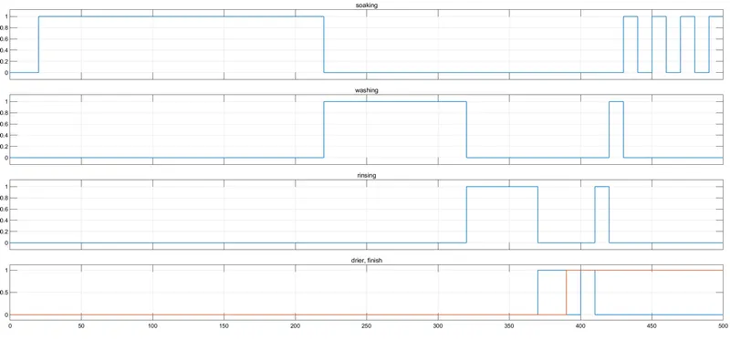
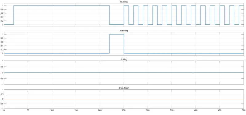
Observation:- When both the power supply and the water supply is ON then both the input condition are 1 and then the next operation of soking will be started for 200 sec as per the delay given, After that washing of the clothes will start for 100 sec and gthen the water which was present in the machine will rinse/drain out for 50 sec and at last the drier will come into action for 20 sec. If alll these four states are completed then the machine will complete its process and the lamp associated with the finish action of wachine will turn Green. Now if in between if the power supply fails, so the arrangements are made such that the process will not be complete and the lamp associated with the completion of process will be red. At last all the signals from the output of states are displayed through a scope.
Model URL:- https://drive.google.com/file/d/1eXioHTm-4u_WQd7-cXwvs62W7KSLBCCE/view?usp=sharing
Resullts:-
Condition 1) When the water supply is avialble till the complete process
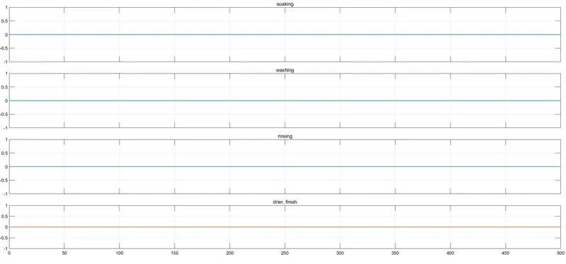
Condition 2) When the water supply is turned OFF
Condition 3) When poer supply wail in between here i have considered that power supply fails at 50% of pulse duration i.e. 250 sec now the results will be
Task 2:- Making a gear shift logic as per the condiyion mentioned in the question
Block used:- Constant, Slider, Chart, Display
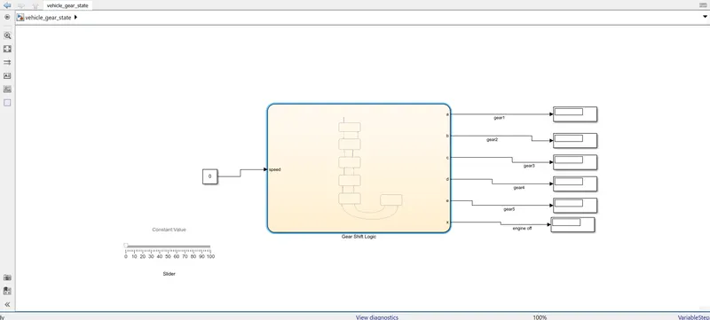
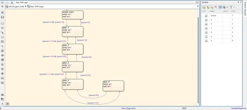
Working of the model:- In this model i have used constant and given it value 0 and i have used slider from the Dashboard from Simulink Library and connected it with the constant block. Then i made a chart and named it gear shift logic and in that chart i have taken input as speed which will come from the slider during run time of the model. And I have created 6 output 5 of which are for the gear denoting number of gear from 1 to 5 (giving those output as a, b, c, d and e) and one is telling the engine off status (x) i.e. when the slider is at 0 position then at that condition the engine will be Off and the diplay assciated with it will be 1. Now the states were made as the gear number here i have created 5 states for each gear and given its entry as 1 and exit as 0 for each of the states and for each state the condition of speed is implemented as mentioned in the question.
Observation:- Now after giving states entry and exit of each states the condition were given for gear 1 when the speed ranges between 0-15 kmph the gear 1 output i.e. a will display 1 and rest all display will be zero as the vehicle speed will be satisfying this state condition only. As such all the gear condition are given and output is observed. Putting run time of simulation to inf and changing the slider we get the excat position of gear in which the vehicle is in their associated display.
Model URL:- https://drive.google.com/file/d/1hw_XHcIiph_hdT_iGSpnlw_AmE_LzggO/view?usp=sharing
Results:-