Project 2
Using MATLAB/simulink and the drive cycle from the attached excel sheet, find-
| Time | Time Step | Battery Current |
| 00:00.4 | 0.1 | -0.9632 |
| 00:00.5 | 0.2 | -0.952 |
| 00:00.6 | 0.3 | -0.9072 |
| 00:00.7 | 0.4 | -0.9632 |
| 00:00.8 | 0.5 | -1.0304 |
| 00:00.9 | 0.6 | -0.9632 |
| 00:01.0 | 0.7 | -1.0304 |
| 00:01.1 | 0.8 | -1.008 |
| 00:01.2 | 0.9 | -0.9856 |
| 00:01.3 | 1 | -0.9632 |
| 00:01.4 | 1.1 | -0.9184 |
| 00:01.5 | 1.2 | -0.9296 |
| 00:01.6 | 1.3 | -0.9296 |
| 00:01.7 | 1.4 | -0.9296 |
| 00:01.8 | 1.5 | -0.9184 |
| 00:01.9 | 1.6 | -0.9408 |
| 00:02.0 | 1.7 | -0.896 |
| 00:02.1 | 1.8 | -0.9072 |
| 00:02.2 | 1.9 | -0.9072 |
| 00:02.3 | 2 | -0.9408 |
| 00:02.4 | 2.1 | -0.9296 |
| 00:02.5 | 2.2 | -0.9296 |
| 00:02.6 | 2.3 | -0.9968 |
| 00:02.7 | 2.4 | -0.9968 |
| 00:02.8 | 2.5 | -0.9408 |
| 00:02.9 | 2.6 | -0.9408 |
Consider the battery resistance is 0.5 mOhm, delta time is 0.1 and entropic factor is 2.
a. The max heat generation of the battery
Ans.
As we know according to Ohm's law
V = I*R ----- (1)
Also
P (Power) = V*I -------(2)
Using equation (1) in (2)
P = I*I*R = I^2*R
H (Joules Heat Generated)= ∫P.dt (limits : 0 to t)
H = I^2*R*t
Here for maximum heat calculation the current I should be Max out of all current data and the time (t) of the same instance
Imax = -0.896
and
t = 1.7
The Given parameters are
R = 0.5 mΩ
Δt = 0.1
Entropy Factor = 2
Maximum heat generated = maximum joule heat +Entropy Heat
Maximum joule heat -
The heat generated in Resistor is directly proportional to Current through it and the time for which the current is passed through.
Entropy Heat -
As electrochemical reactions take place inside a battery, heat is produced owing to the change in entropy. Entropy heat, or reversible heat, is produced when the open circuit voltage changes in relation to the temperature at two electrodes.
Maximum joule heat = I^2*R*t
= (-0.896)^2*0.5m*1.7
= 0.000682393J
Maximum heat generated = 0.000682393 +2
= 2.000682393 J
_____________________________________________________________________________________
b. The SOC of the battery at 2 *104second of the battery operation
Ans.
The SoC (State of Charge) refers to the ratio of the amount of charge present in the cell/battery at a particular moment to the Maximum charge (according to the SoH).
SoC = Q/Qmax
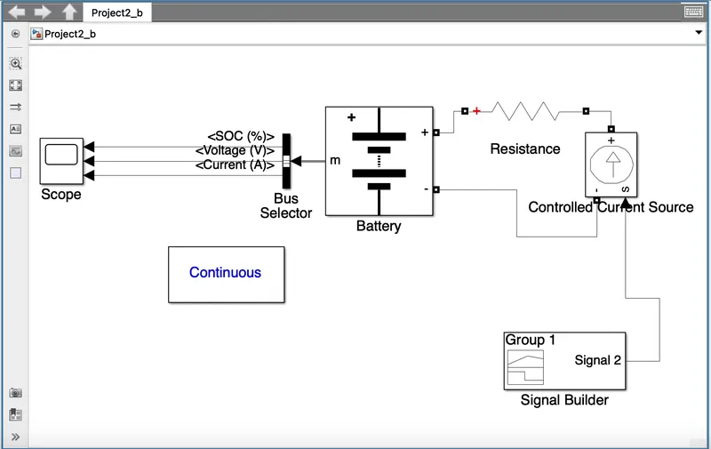
Blocks used in the simulation are
1. Battery-
This model uses a generic battery model to implement the majority of common battery types. For the Lithium-Ion battery type, temperature and age (from cycling) impacts can be set.
2. Controlled Current source -
It creates an analogous current source from the Simulink input signal. The block's input signal drives the produced current.
Your circuit can be initialised with a particular AC or DC current. The block input has to be linked to a signal beginning as a sinusoidal or DC waveform corresponding to the initial values if you want the simulation to begin in steady-state.
3. Bus Selector -
Using a Bus Maker, Bus Selector, or a block that uses a bus object to determine its output, this block can receive a bus as input. The input bus's components are displayed in the left listbox. To choose the output elements, use the Choose button. The choices are displayed in the right listbox. To reorganise the options, press the Up, Down, or Delete button. To export a single bus, select "Output as virtual bus."
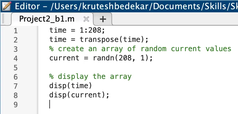
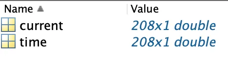
4.Signal Builder Block -To use any type of current signal till 208 stop time. Which is generated using the following code
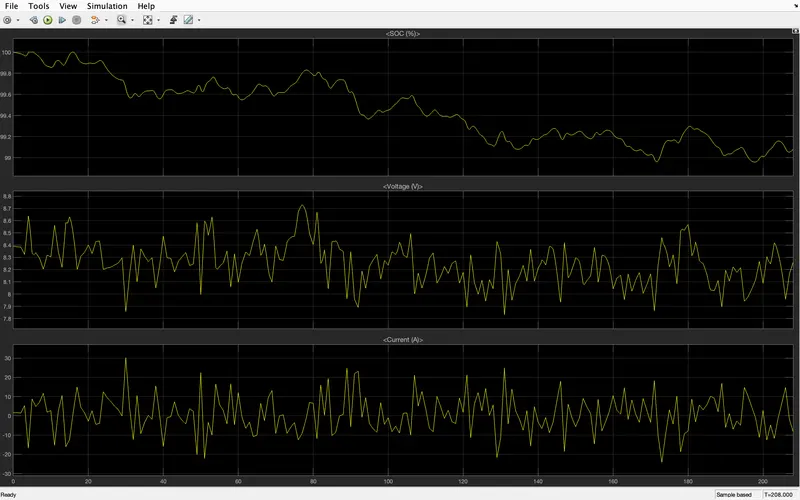
The above plot on scope is shown for the 2*104 sec (208 sec) and the variation can be observed for SOC, Voltage and Current.
_____________________________________________________________________________________