Project 1
AIM- To Analyze and design a steel building to 10T CRANE as per IS standard code in TEKLA STRUCTURAL DESIGNER.
Consider dead, live, equipment and wind loading. Consider the brick wall loading for 150mm thick and 1.5 KN per sq m for wall and roof cladding.
Assume wind loading basic speed as 39m/s
Report of each member to be generated and extract drawings of structural plans from the software.
PROCEDRE-
CREATION OF NEW MODEL IN TEKLA-
- Open TEKLA software.
- Create new file
MODELLING OF CONSTRUCTON LEVELS-
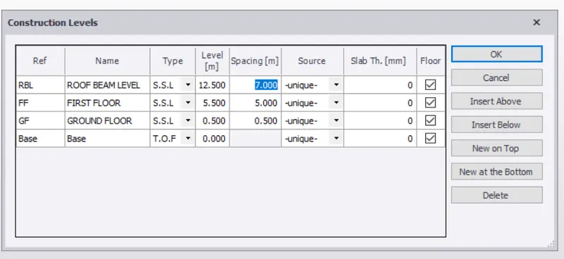
- Go to the model tab and select construction levels.
- In- Base > construction type > T.O.F ( top of foundation) SPACING 0 M.
- In ground floor > construction type >S.S.L ( structural slab level ) SPACING 0.5 M.
- In first floor >construction type >S.S.L ( structural slab leve )SPACING 5 M.
- In roof beam level > construction type > S.S.L ( structural slab level ) SPACING 7 M.
MODELLING OF GRIDS-
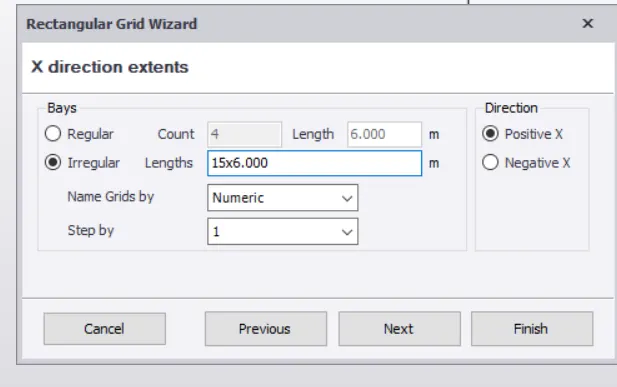
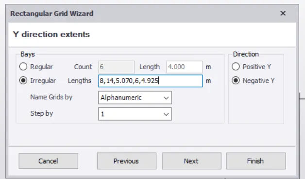
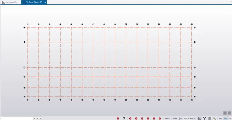
- Go to the model tab and select grids and select as rectangular wizard.
- Enter the data in the dialog box as follows.
DEFINING AND DRAWING OF CONCRETE PEDESTAL-
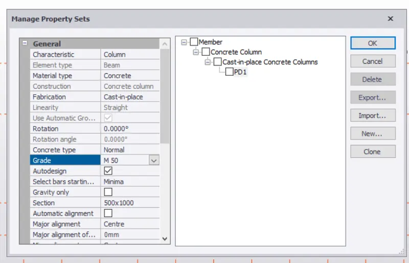
- First define the Column Properties.
- Go to Home- Manage Property Sets- New- Concrete column.
- Rename the concrete column as PD1. (Concrete Pedestal)
- Set the dimension of Concrete column as 500X1000 mm.
- Set the grade of column as M50.
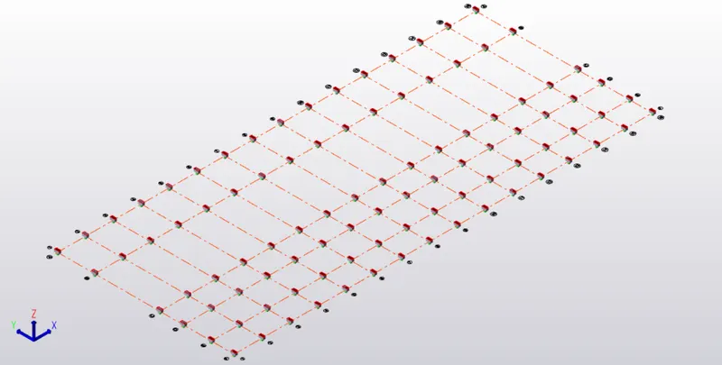
- For drawing the column go to model tab in ribbon and draw the column.
- Select levels as select base level as base level and top level as ground floor level.
- Place the concrete columns wherever required
DEFINING AND DRAWING OF STEEL COLUMN-
- First define the Column Properties.
- Go to Home- Manage Property Sets- New- steel column.
- Rename the steel column as C1.
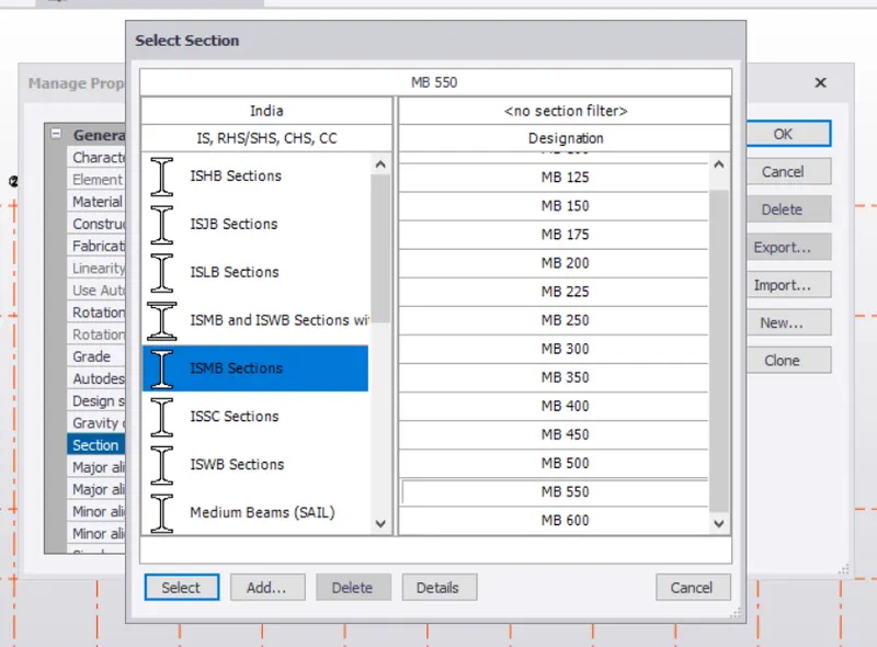
- Set the type of column of ISMB550.
- For drawing the column go to model tab in ribbon and draw the column.
- Select levels as select base level as ground floor level and top-level roof beam level.
- Place the steel columns wherever required
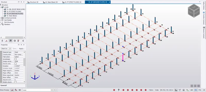
DEFINING AND DRAWING OF STEEL BEAM-
- First define the Beam Properties.
- Go to Home- Manage Property Sets- New- steel beam.
- Rename the beam as B1.
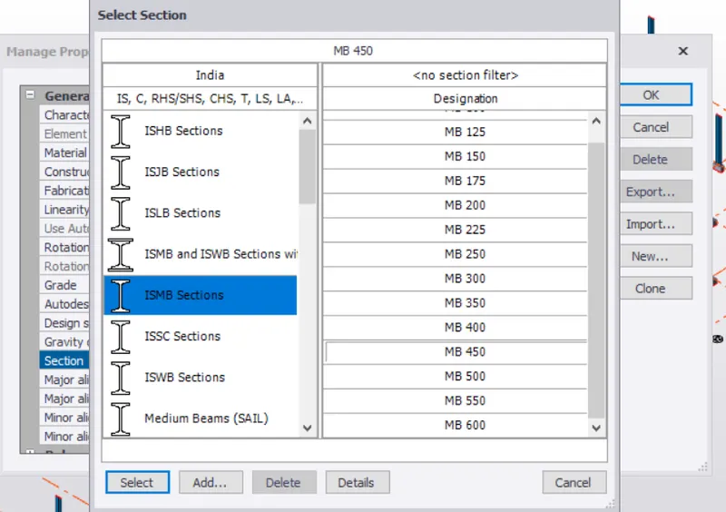
- Set the type of beam as ISMB450.
- For drawing the beam go to model tab in ribbon and draw the beam.
- Draw the steel beams wherever require
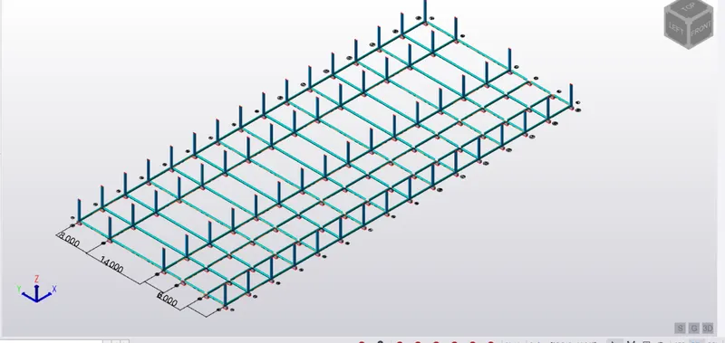
GROUND FLOOR BEAM ARRANGEMENT-
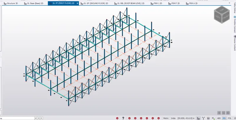
FIRST FLOOR BEAM ARRANGEMENT-
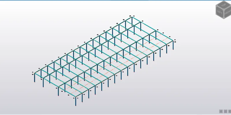
ROOF BEAM LEVEL BEAM ARRANGEMENT-
DEFINING AND DRAWING OF RAFTER-
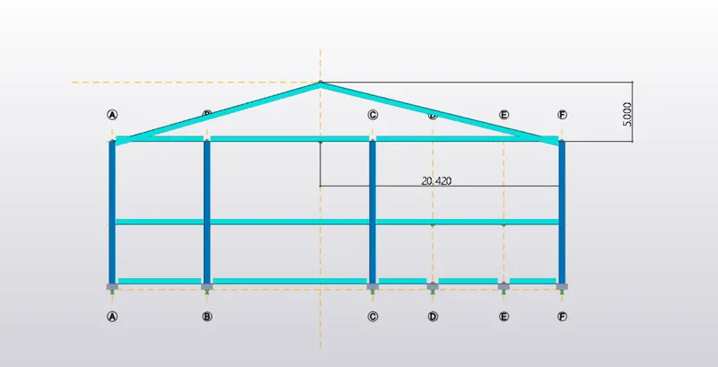
- Modelling and drawing of RAFTER steel beam.
- First define the Beam Properties.
- Go to Home- Manage Property Sets- New- Steel Beam.
- Rename the beam as rafter and select section as ISMB400
- For drawing the rafter beams go to model tab in ribbon and draw the beams.
- Select appropriate frame and then draw the rafter beam.
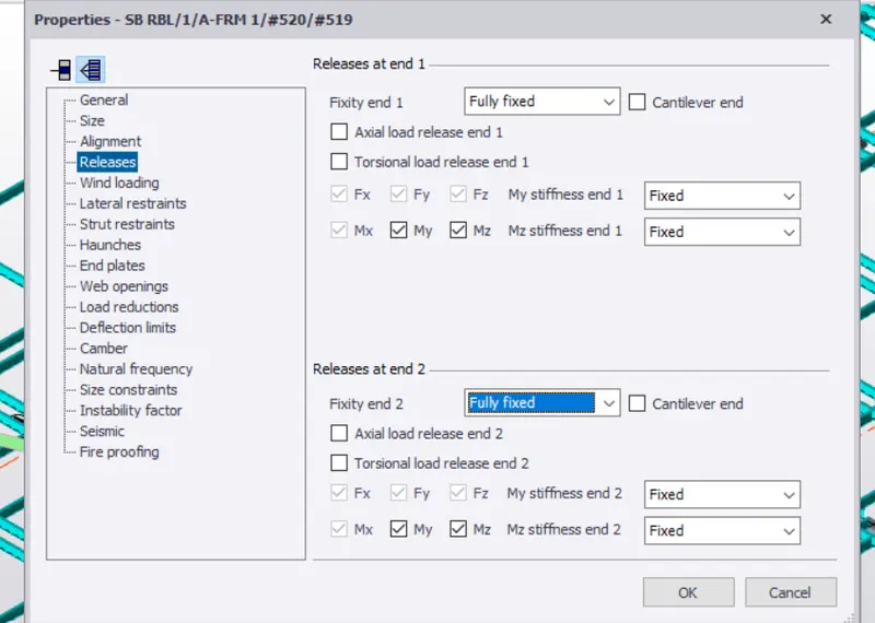
- Change the releases of rafter beam to fully fixed.
CHANGING THE RELEASES OF RAFTER TO FULLY FIXED-
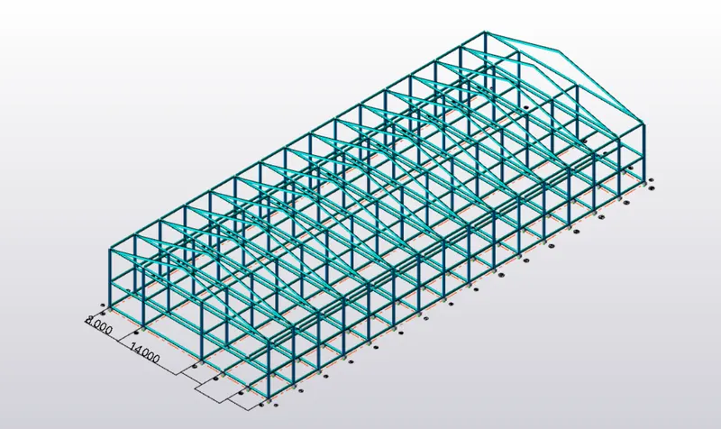
DEFINING AND DRAWING OF BRACINGS-
- Modelling and drawing of bracings.
- First define the bracing Properties.
- Go to Home- Manage Property Sets- New- Steel Brace.
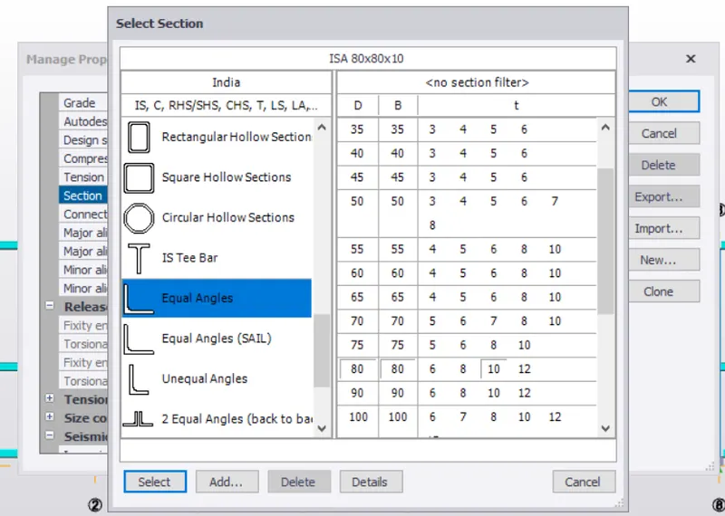
- Rename the brace and select section as L section 80 X 80 X 10
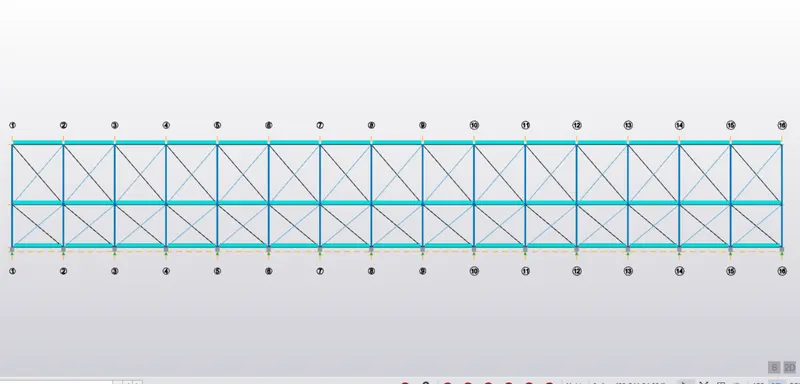
- For drawing the bracing go to model tab in ribbon and select brace and draw X bracings.
FIXING SIZE OF BRACING-
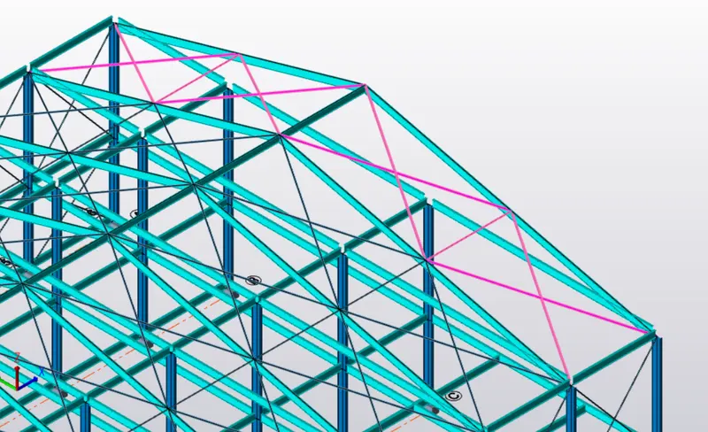
DRAWING OF PLAN BRACINGS-
DEFINING AND DRAWING OF RIDGE BEAM-
- Modelling and drawing of RIDGE steel beam.
- First define the Beam Properties.
- Go to Home- Manage Property Sets- New- Steel Beam.
- Rename the beam as ridge and select section as ISMB400
- For drawing the beams go to model tab in ribbon and draw the beams.
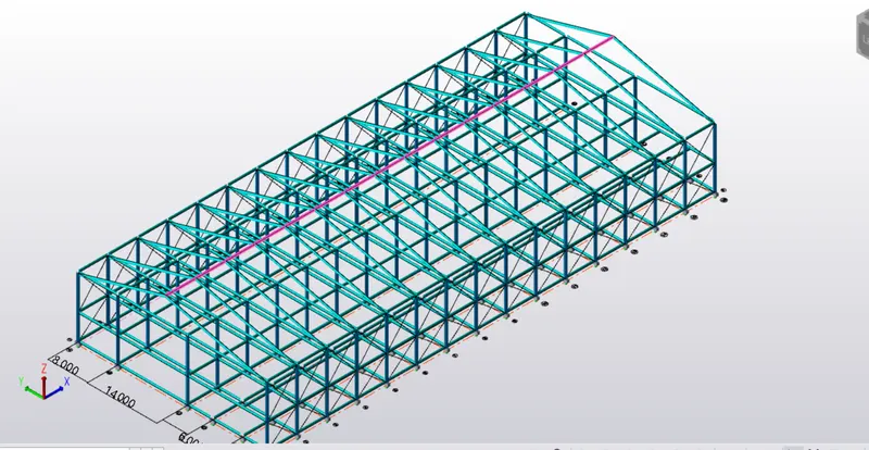
- Draw the ridge beam in connection to the rafter beams modelled and drawn earlier.
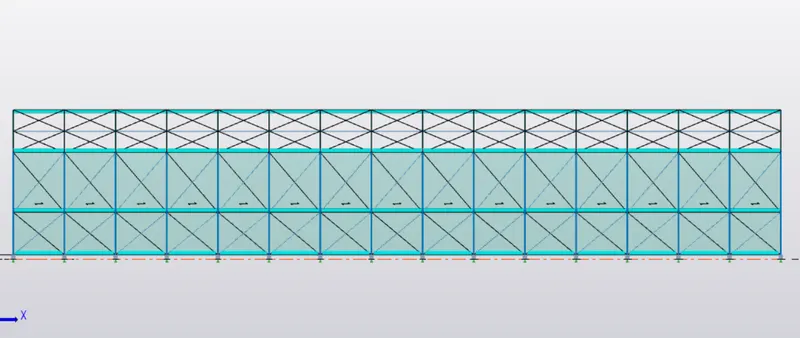
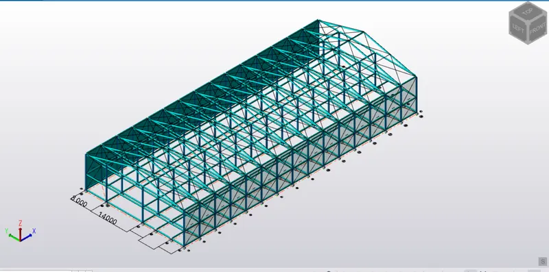
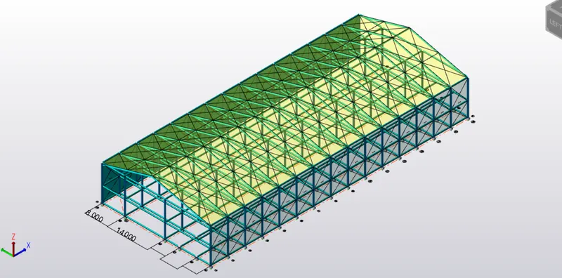
MODELLING AND DRAWING OF ROOF AND WALL PANEL-
- Go to the model tab and select roof panel.
- Draw the panels to the roof.
- Similarly select the wall panel and draw wall panels.
WALL PANELS-
ROOF PANEL-
DEFNING AND DRAWING OF SLABS-
- Defining slab section.
- Go to Home tab.
- Home- Manage property sets- new- slab item.
- Select slab type as slab on beams, type as reinforced concrete slab, grade of concrete as M50, thickness of slab as 350mm.
- Select reinforcement and select bar size as 16mm and spacing as 150mm.
- Define two types of slab- One way slab and Two-way slab.
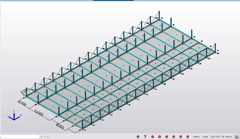
- For drawing of slab go to model tab and select slab and place the slabs at required position
SLAB DETAILS OF GROUND FLOOR-
SLAB DETAILS OF FIRST FLOOR-
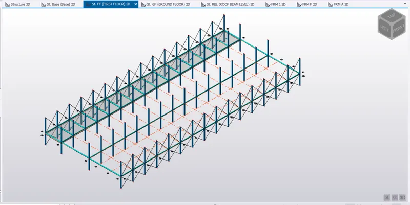
SLAB DETAILS OF SLAB BEAM LEVEL-
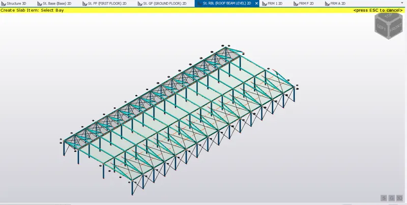
CALCULATION OF LOADS-
CALCULATION OF FLOOR FINISH LOAD-
- Thickness of finish is 50mm (0.05m)
- Density of concrete=24
- Hence, Floor finish load= 0.05 X 24 = 1.2 KN/m^2.
CALCULATION OF SLAB LOAD-
- Slab will be designed by TEKLA software.
CALCULATION OF BRICKWALL LOAD-
- Thickness of brick wall= 150mm
- Unit weight of Brick wall as per IS code= 20 KN/m^3.
Load of brick wall-
For ground floor-
- Height of wall on ground floor= 5m.
- Hence Brick wall load= 5 X 0.15 X 20= 15KN/m.
For Fist floor-
- Height of wall on First floor= 7m.
- Hence Brick wall load= 7 X 0.15 X 20= 21KN/m.
CEILING LOAD- 0.3KN/m^2. (FOR NON-ACCESSIBLE FLOORS)
ROOFING LOAD BASED ON PURLIN SIZE = 1.5KN/m^2 (Given)
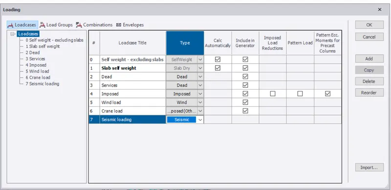
ADDING LOAD CASES-
- Go to Load tab in ribbon.
- Select load cases, a pop-up window of loads will be opening on the screen
- Add new load cases as Wind load, Crane load and seismic load
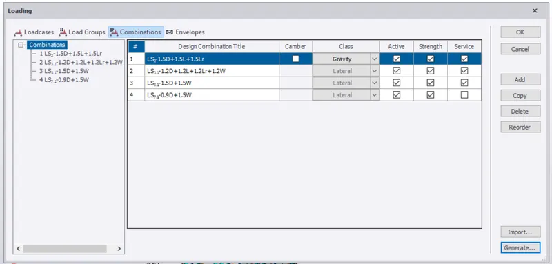
GENERATING LOAD COMBINATIONS-
- Go to Load tab in Ribbon.
- Select load combinations and select Generate.
- After that select delete all previous load and select Next.
- The load combinations will be generated at the end.
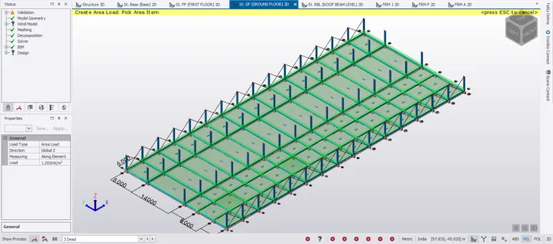
APPLYING DEAD LOAD AS FLOOR FINISHES ON SLABS IN THE MODEL-
- Select Ground Floor.
- In the bottom of the screen there is a draw down panel select DEAD in the panel.
- Click on load- Area load and apply loads to all the slabs.
- Select the load value as 1.2KN/m^2
- Assign the loads to Ground and First floor and slab beam level.
GROUND FLOOR-
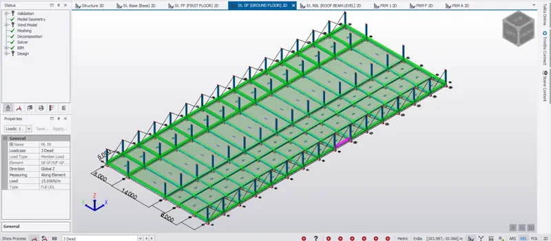
APPLYING BRCKWALL LOAD-
- Select Ground Floor.
- In the bottom of the screen there is a draw down panel select DEAD in the panel.
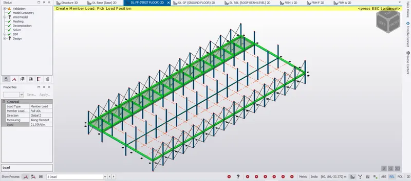
- Click on load- Full UDL and apply loads to all the beams and where there are walls present.
- For ground floor select load value as 15KN/m.
- For First floor select load value as 21Kn/m.
- Select line load where there is no beam and wall load are to be assigned.
BRICKWALL LOAD FOR GROUND FLOOR-
BRICKWALL LOAD FOR FIRST FLOOR-
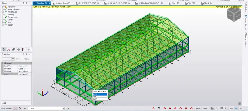
APPLYING DEAD LOAD ON ROOF PANEL AND CEILING-
- In the bottom of the screen there is a draw down panel select DEAD in the panel.
- Click on load- Area load and apply loads on ceiling slabs
- Select the load value as 0.3KN/m^2.
- Apply Load of 1. 5KN.m^2 for roof panel.
LIVE LOAD CONSIDERATIONS-
LOADINGS CONSIDERED AS PER IS 875- 1987 (PART 2)-
- Meeting Room – 5KN/m^2.
- Office – 5KN/m^2.
- Rest room – 3KN/m^2.
- Toilet – 2KN/m^2.
- Administration office – 3KN/m^2.
- Workshop - 10KN/m^2.
- Corridor –5KN/m^2.
- Staircase- 5KN/m^2.
- Pantry – 3KN/m^2.
- Store – 5KN/m^2.
- Equipment room – 5KN/m^2.
- Maintenance yard- 10KN/m^2.
- Flat roof (Non accessible) – 0.75KN/m^2.
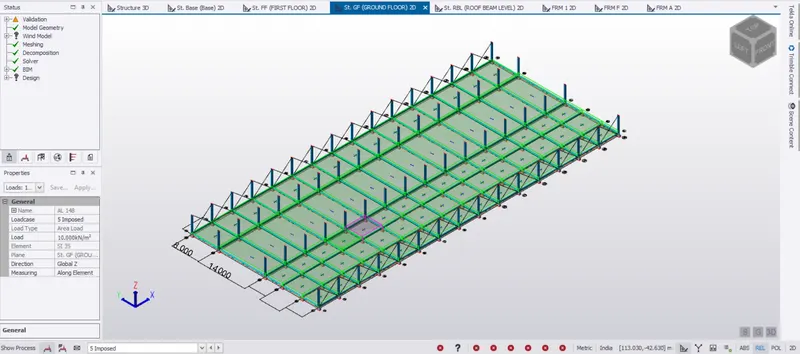
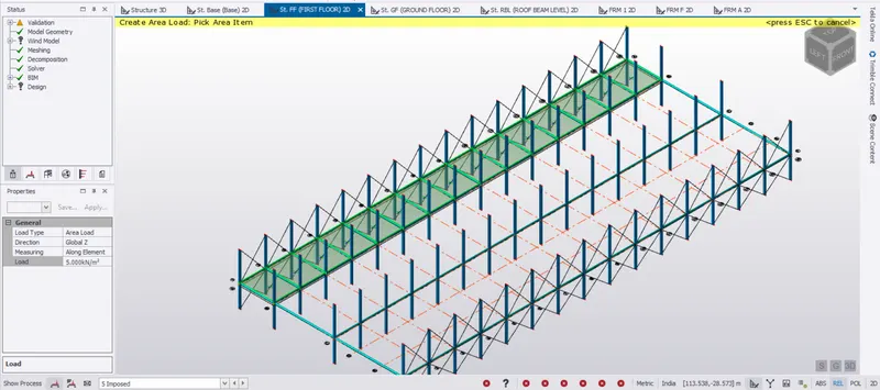
APPLYING LIVE LOAD ON SLABS AS PER THE LOADINGS MENTIONED IN IS 875- 1987 (PART 2)
- Select Ground Floor.
- In the bottom of the screen there is a draw down panel select IMPOSED in the panel.
- Click on load- Area load and apply loads to all the slabs.
- Select the load value as per the rooms.
- Assign the loads to Ground and First floor ceiling floor that is roof beam level
LIVE LOAD ASSIGNED ON GROUND FLOOR-
LIVE LOAD ASSIGNED ON FIRST FLOOR-
WIND LOAD CALCULATIONS-
- Basic wind speed = 39m/s
- Terrain category 2
- Life of structure – 50years. (Clause 5.9.1)
- Total length of building (l) = 90m.
- Total height of building (h)= 12m.
- Total width of building (w)= 38m.
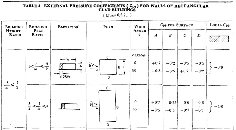
l/w = 90/38 = 2.36.
h/w = 12/38 = 0.31.
h/w is smaller than 0.5.
l/w is greater than 1.5.
Take building ratio height as (h/w < 1/2).
Take building plan ratio as (3/2< l/w < 4)
(TABLE 4 EXTERNAL PRESSURE COEFFICIENTS ( Cpe ) FOR WALLS OF RECTANGULAR CLAD BUILDINGS)
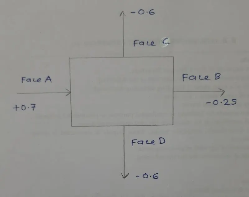
Cpi-
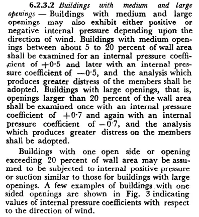
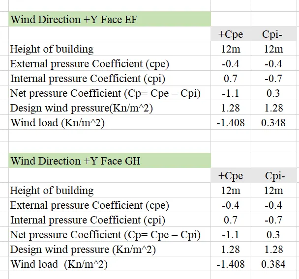
The internal pressure coefficienr Cpi is +0.7 , -0.7
STEP 1- Calculation of factors K1, K2, K3, K4.
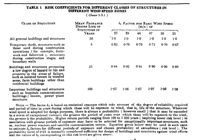
K1= 1 (Probability factor)
For probable life of structure = 50 years and basic wind speed = 39m/s.
(TABLE 1 RISK COEF’FICIENTS.FOR DIFFERENT CLASSES OF STRUCTURES IN DIFFERENT WIND SPEED ZONES ( Clause 5.3.1 ))
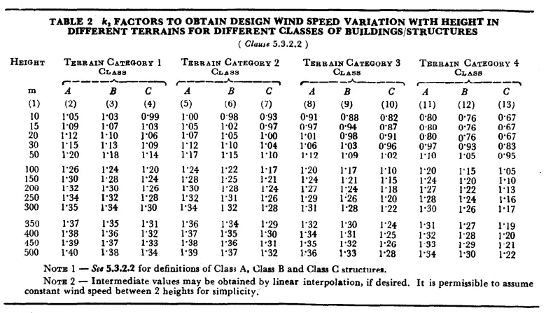
K2 (Terrain category)-
TABLE 2 k2, FACTORS TO OBTAIN DESIGN WIND SPEED VARIATION WITH HEIGHT IN DIFFERENT TERRAINS FOR DIFFERENT CLASSES OF BUILDINGS/STRUCTURES (Clause 5.3.2.2)
By interpolation between the height of the building 10m and 15m.
The height of building given is 12m
Hence k2 factor for terrain category 2 and class of building A = 1.03 by interpolation.
Hence K2 = 1.03
K3 (Topography factor)-
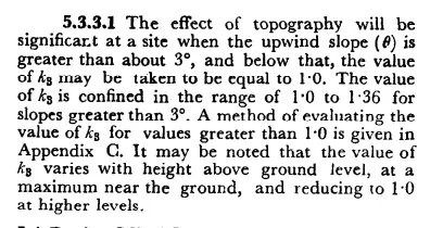
Clause 5.3.3
K3 = 1.
K4 ( Importance factor)-
K4 = 1.15 for industrial structure
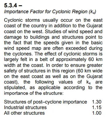
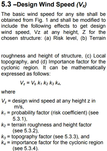
STEP 2- Calculation of design wind speed(Vz)-
Vz= Vb X k1 X k2 X k3 X k4.
Vz= 39 X 1 X 0.03 X 1 X 1.15.
Vz = 46.19 m/s
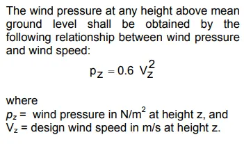
STEP 3- Calculation of design wind pressure (Pz)-
Pz= 0.6 X Vz2
Pz = 0.6 X 46.192
Pz = 1.28 KN/m^2

ROOF CALCULATION-
Roof angle = 20 degrees.
TABLE 5 EXTERNAL PRESSURE COEFFICIENTS ( cpe, ) FOR PITCHED ROOFS OF RECTANGULAR CLAD BUILDINGS (Clause 6.2.2.2
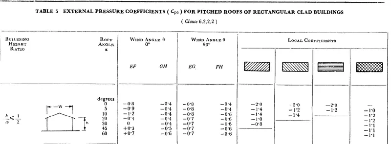
Take building height ratio as h/w< 1/2
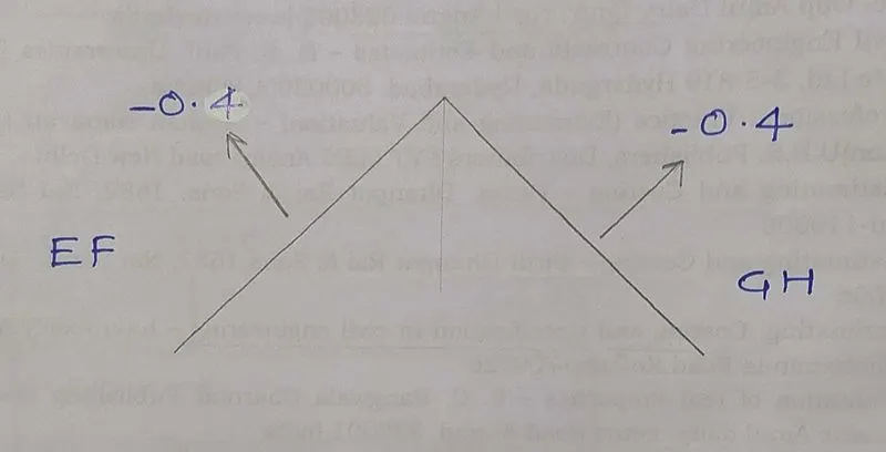
Consider the cpe factors as
For EF = -0.4
For GH= -0.4
ADDING AND APPLYING ALL THE WIND LOADCASES IN THE MODEL-
- Wind + Y + Cpi
- Wind + Y - Cpi
- Wind + X + Cpi
- Wind + X - Cpi
Generating a calculation for 10T crane loading based on following inputs-
- Crane capaciy = 100KN
- Weight of crab = 40 KN
- Number of wheels = 4
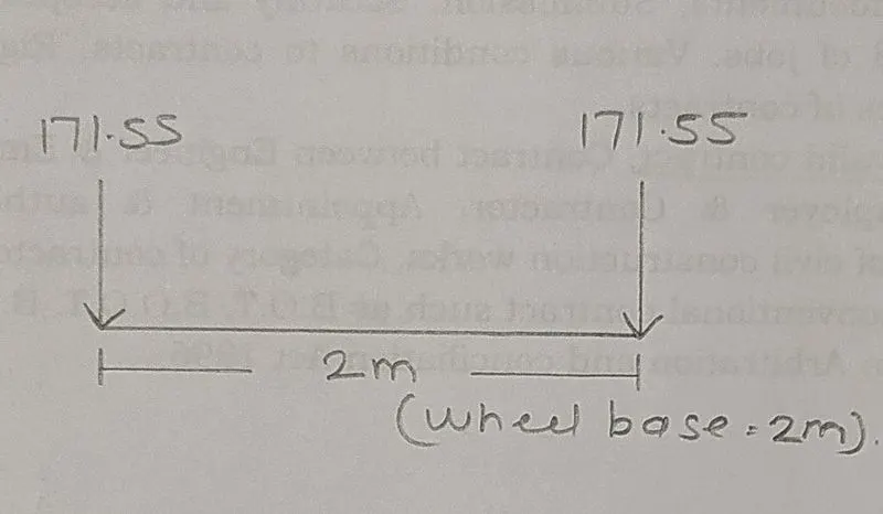
- Wheel base = 2m.
- Span of crane (c/c of gantry rail) = 20m.
- Distance between c/c of gantry column = 8m
- Minimum hook approach =1m.
STEP 1- Calculation of maximum wheel load-
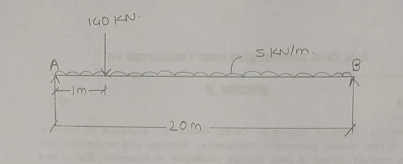
Point load = Crane capacity + weight of crab
= 100 + 40= 140KN.
UDL of span = crane capacity / span length = 100/20 = 5KN/m
Calculation of Reactions-
Ra + Rb = 140 +(5 X 20) = 240 KN
Ra + Rb = 240 KN.
Taking moment at A-
(140 X 1) + (5 X 20 X 10) – 20Rb = 0
Rb =57 KN
Ra = 183 KN
Ra is greater than Rb
Hence maximum wheel load = 183 KN.
Load at each wheel = 183 / 2 = 91.5 KN.
According to IS 875 (part 2) add impact load 25% of wheel wheel load.
91.5 + 91.5 X 25/100. =114.37 KN.
Factored load = 1.5 X 114.37 = 171.55 KN
STEP 2- Maximum Bending Moment for Gantry Girder-
- Self-weight of gantry girder = 1.6KN/m.
- Weight of rails = 0.3KN/m.
- Total weight = 1.6 +0.3 = 1.9.
- Factored weight = 1.5 X 1.9 = 2.85KN/m
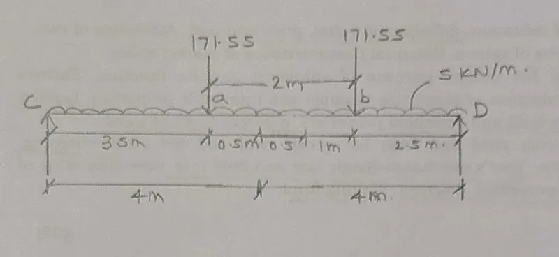
Taking moment at D-
( Rc X 8 ) – ( 5 X 8 X 4 ) – (171.55 X 4.5 ) – ( 171.55 X 2.5 ) =0
8Rc = 1360.85 KN.
Rc = 170.10 KN.
Rc + Rd = 171.55 + 171.55 + ( 5 X 8 )= 383.1 KN
Hence Rd = 213 KN
Maximum moment at wheel A
Ma= ( 170.10 X 3.5 ) – ( 5 X 3.5 X 1.75 ) = 564.725 KN.m
Maximum moment at wheel B-
Mb = ( 213 X 2.5 ) – ( 5 X 2.5 X 1.25 ) = 516.875 KN/m
STEP 3 – CALCULATION OF MAXIMUM SHEAR FORCE.
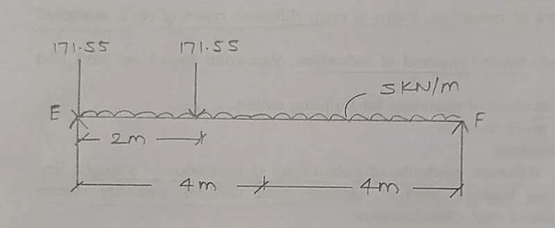
Re + Rf = 171.55 +171.55 + (5 X 8) = 383.1 KN
Taking moment at E-
(171.55 X 2) + ( 5 X 8 X 4 ) -8 Rf = 0
503.1 = 8Rf
Rf = 62.88 KN.
Re + Rf = 383.1 KN
Hence Re = 320.22 KN.
SURGE LOAD – according to Is 875 part 2 page 15.
Total surge load = 10% ( crane capacity + crab weight )
= 10/100 ( 100 + 40)
= 14KN.
Surge load on each wheel = 14/4 = 3.5 KN.
Factored load = 1.5 X 3.5 = 5.25 KN.
LATERAL FORCES-
Maximum horizontal reaction due to lateral force by proportion at E=
Lateral force X reaction due to vertical load E / max wheel load.
= 5.25 X 320.22 / 171.55 = 9.79 KN
Maximum horizontal reaction due to lateral force by proportion at F=
Lateral force X reaction due to vertical load F / max wheel load.
= 5.25 X 62.88 / 171.55 = 1.92 KN
Total lateral force = 9.79 + 1.92 = 11.71 N
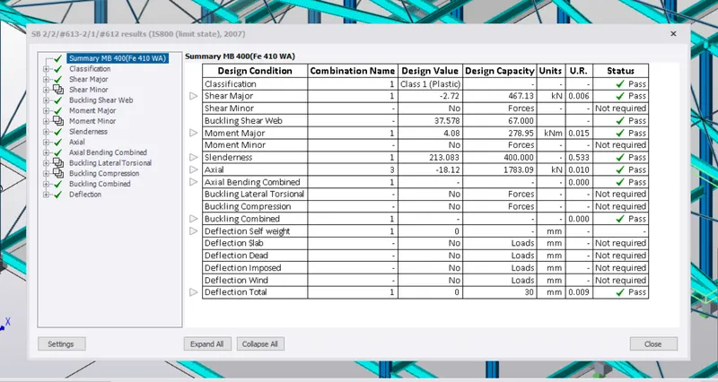
RESULTS OF MEMBERS DESIGNED-
COLUMN-
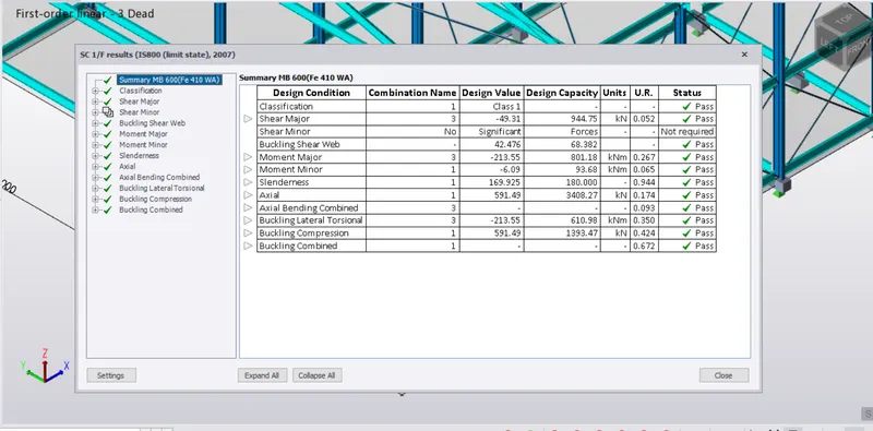
BEAM-
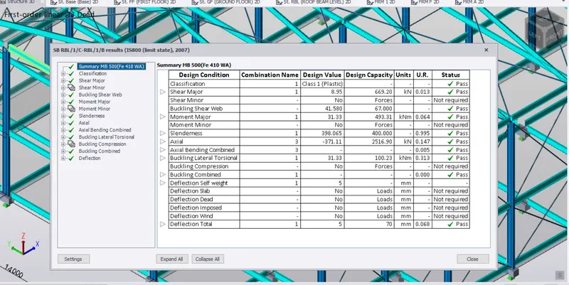
RIDGE-
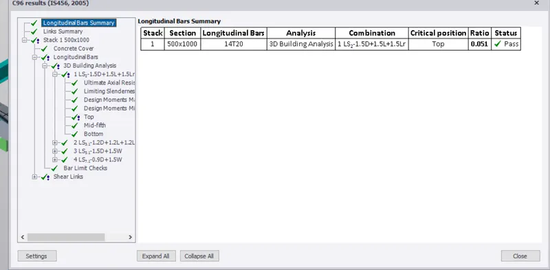
CONCRETE PEDESTAL-