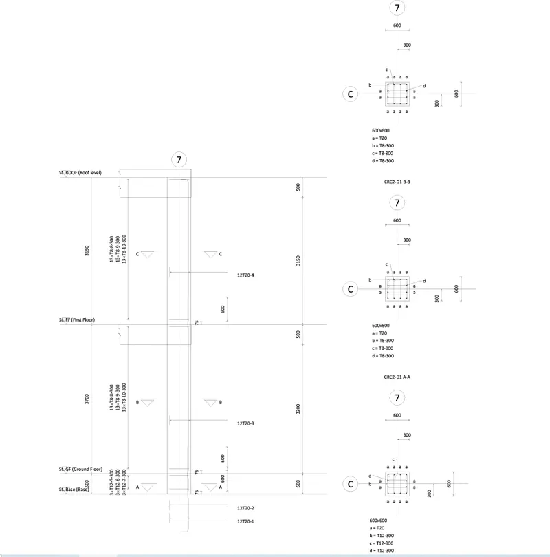
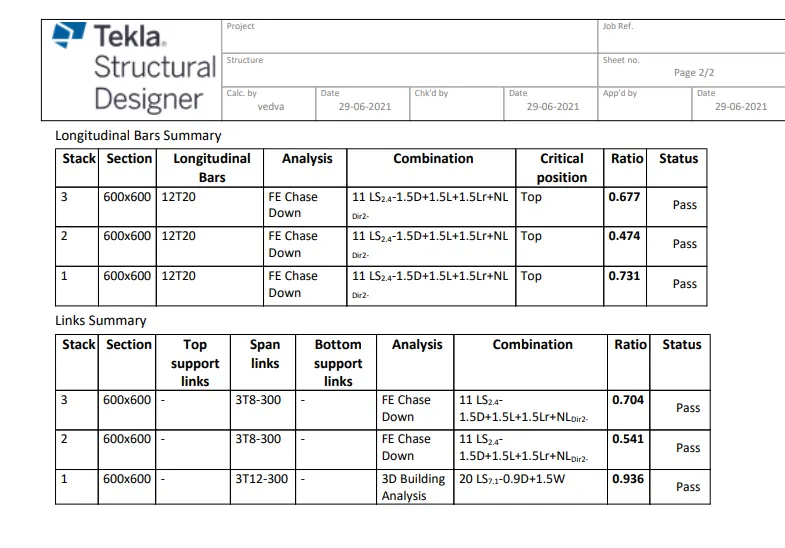
Project 2
PROJECT 2
Develop general arrangement for the RC office building. Analyze and design the building as per IS standard code in TEKLA STRUCTURAL DESIGNER. Refer the attached plan and elevation. The building to be designed for dead, live, wind and seismic loading.
Report of each member to be generated and extract drawings for structural plans, beam reinforcement details from the software
AIM- TO ANALYZE AND DESIGN RC BUILDING USING TEKLA STRUCTURAL DESIGNER AND CREATE REPORT.
PROCEDRE-
CREATION OF NEW MODEL IN TEKLA-
- Open TEKLA software.
- Create new file.
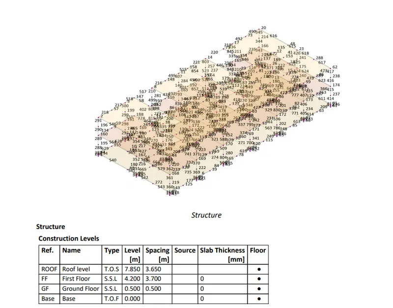
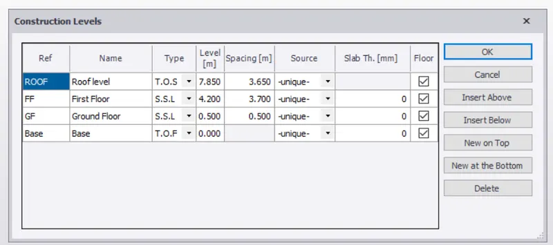
MODELLING OF CONSTRUCTON LEVELS-
- Go to the model tab and select construction levels.
- In- Base > construction type > T.O.F ( top of foundation) SPACING 0 M.
- In ground floor > construction type >S.S.L ( structural slab level ) SPACING 0.5 M.
- In first floor >construction type >S.S.L ( structural slab leve )SPACING 3.7 M.
- In roof level > construction type > T.O.S ( top of steel ) SPACING 3.625 M.
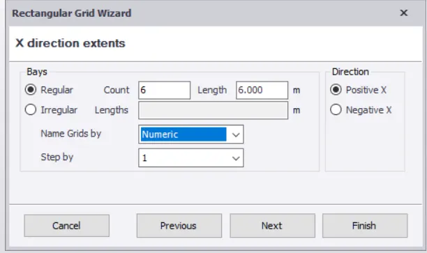
MODELLING OF GRIDS-
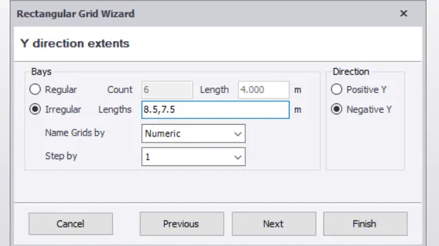
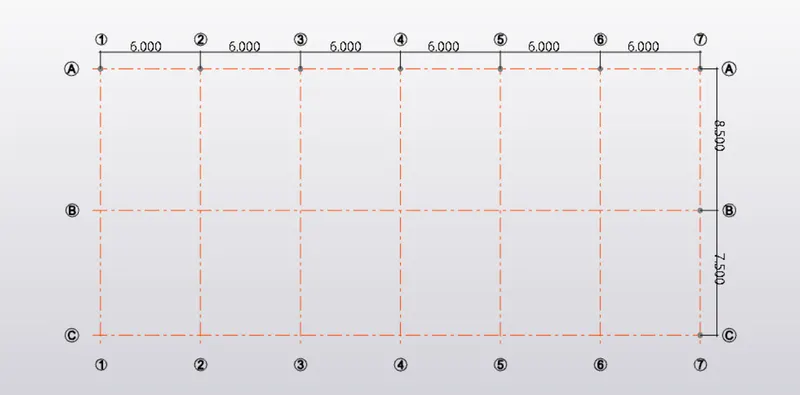
- Go to the model tab and select grids and select as rectangular wizard.
- Enter the data in the dialog box as follows.
DEFNING AND DRAWING OF CONCRETE COLUMN-
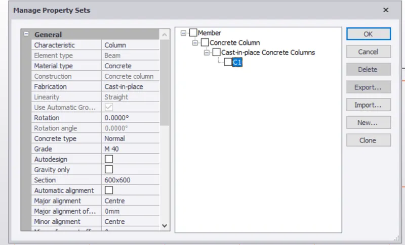
- First define the Column Properties.
- Go to Home- Manage Property Sets- New- concrete column.
- Rename the steel column as C1.
- Set the size of column as 600 X 600.
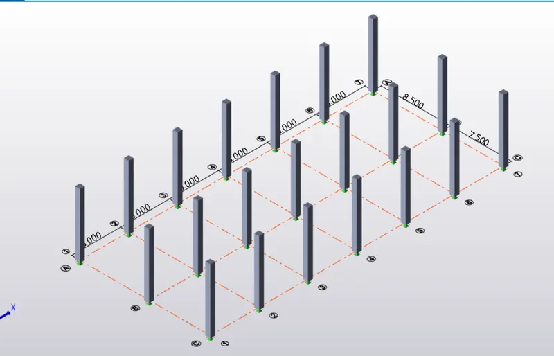
- For drawing the column go to model tab in ribbon and draw the column.
- Select levels as select base level as ground floor level and top level as roof level.
- Place the concrete columns wherever required.
DEFINING AND DRAWING OF CONCRETE BEAM-
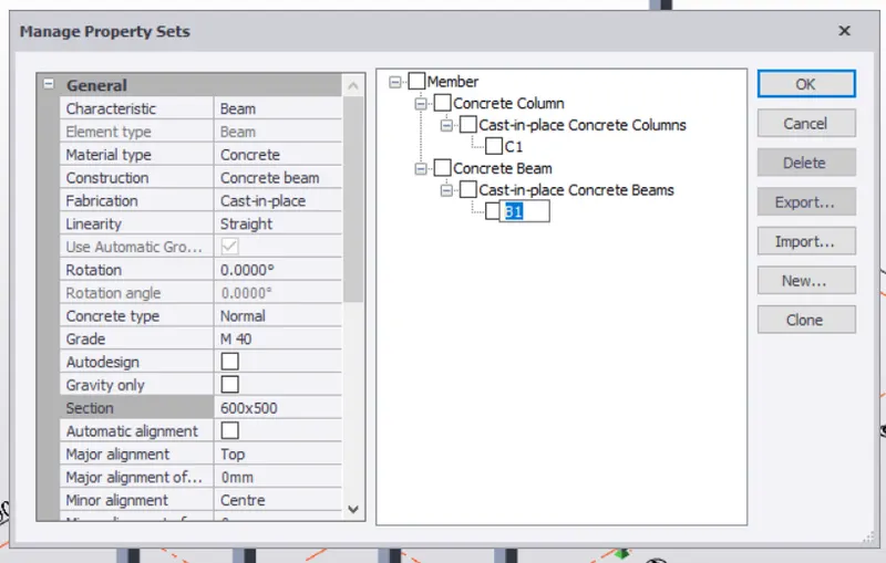
- First define the Beam Properties.
- Go to Home- Manage Property Sets- New- Concrete beam.
- Rename the beam as B1.
- Set the size of beam as 600 X 500.
- For drawing the beam go to model tab in ribbon and draw the beam.
- Draw the concrete beams wherever require
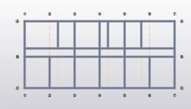
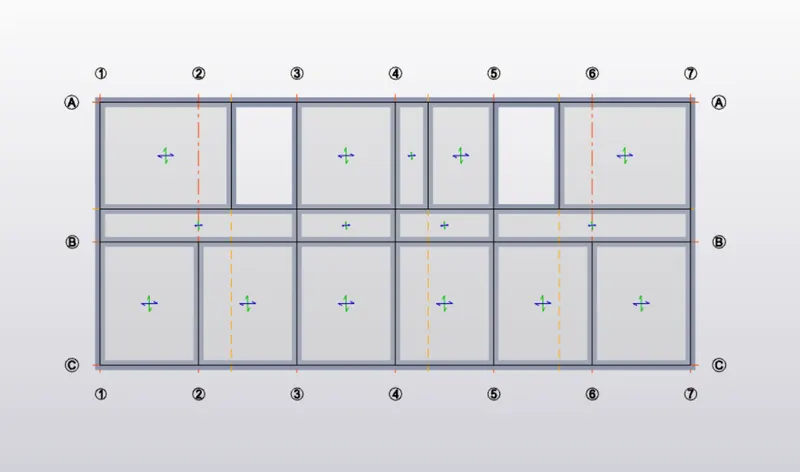
GROUND FLOOR, FIRST FLOOR AND ROOF FLOOR BEAM ARRANGEMENT-
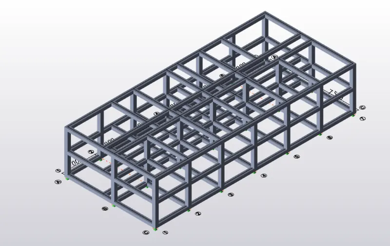
3D VIEW OF BEAM ARRANGEMENT-
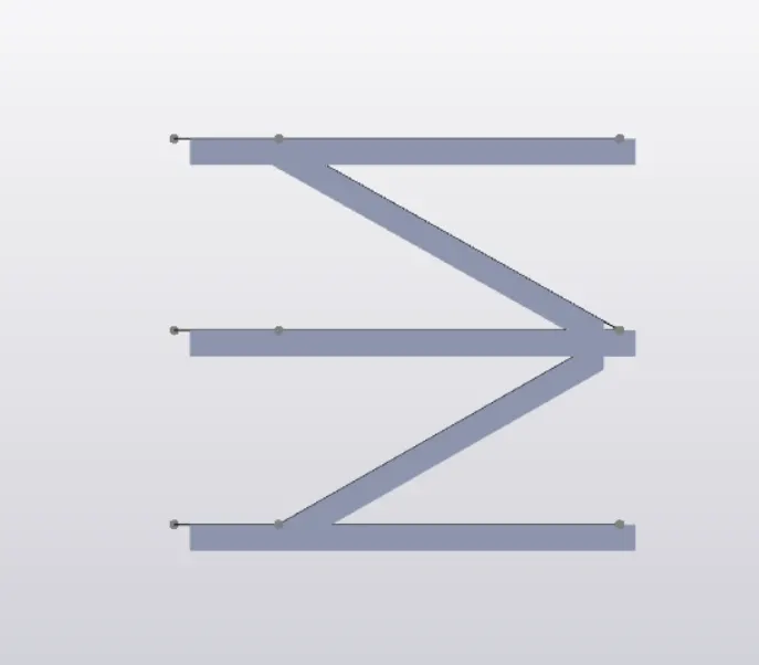
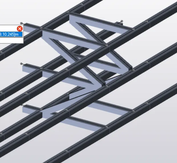
DRAWING OF STAIRCASE BY CREATING SUBSTRUCTURE-
- Select the appropriate Beams on ehich Staircase is to be held.
- SElect tyhe beams and right click and select Add to substructure.
- Select the Substructure view and draw the inclined beam for resting of stairs.
DEFINING AND DRAWING OF CONCRETE SLABS-
- Defining slab section.
- Go to Home tab.
- Home- Manage property sets- new- slab item.
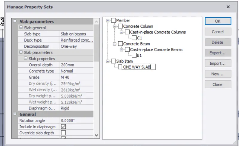
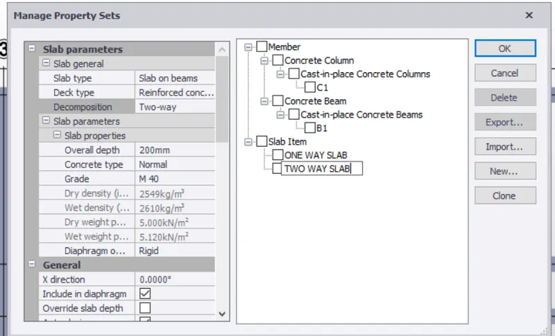
- Select slab type as slab on beams, type as reinforced concrete slab, grade of concrete as M40, thickness of slab as 200mm.
- Define two types of slab- One way slab and Two-way slab.
- For drawing of slab go to model tab and select slab and place the slabs at required position.
ONE WAY SLAB DETAILS-
TWO WAY SLAB DETAILS-
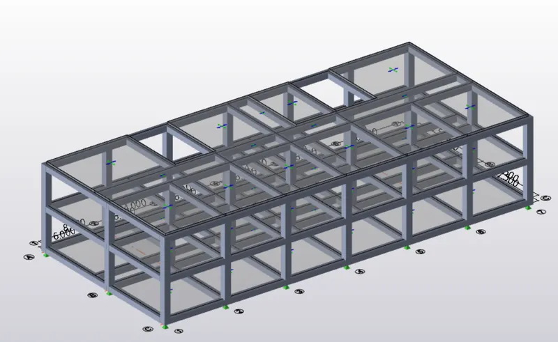
SLAB ARRANGEMENT DETAILS FOR GROUND, FIRST AND ROOF FLOOR-
3D IMAGE OF SLABS- (ALL STOREY)
CALCULATION OF DEAD OAD-
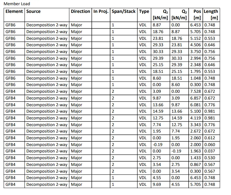
Calculation of dead load in design report based on IS code and apply dead load on the model
- Finishes of 50mm
- Slab thickness as per the design
- Brick wall load
- Roofing load
CALCULATION OF LOADS-
CALCULATION OF FLOOR FINISH LOAD-
- Thickness of finish is 50mm (0.05m)
- Density of concrete=24
- Hence, Floor finish load= 0.05 X 24 = 1.2 KN/m^2
CALCULATION OF SLAB LOAD-
- Slab will be designed by TEKLA software.
CALCULATION OF BRICKWALL LOAD-
Thickness of brick wall= 225mm
Unit weight of Brick wall as per IS code= 20 KN/m^3.
Load of brick wall-
For ground floor-
- Height of wall on ground floor= 3.7m.
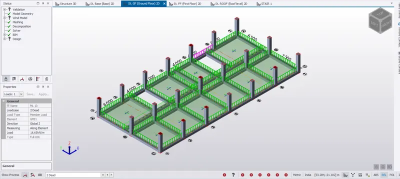
- Hence Brick wall load= 3.7 X 0.225 X 20= 16.65 KN/m.
For Fist floor-
- Height of wall on First floor= 3.650m.
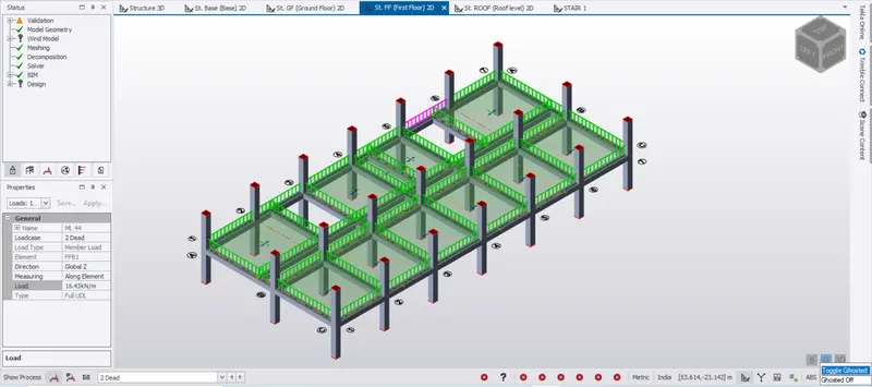
- Hence Brick wall load= 3.650 X 0.225 X 20= 16.425 KN/m
CALCULATION OF ROOFING LOAD-
There will be Parapet wall on the roof so the load of parapet wall should be considered on roof beams.
The slab load of roof will be designed by tekla software.
- Height of Parapet wall = 1m.
- Thickness of wall = 225 mm (0.225m).
- Unit weight of Brick wall as per IS code= 20 KN/m^3.
- Hence dead load of parapet wall = 1 X 0.225 X 20 = 4.5 KN/m
Load of water tank- 20KN/m^2
APPLYING FLOOR FINISH LOAD-
- Select Ground Floor.
- In the bottom of the screen there is a draw down panel select DEAD in the panel.
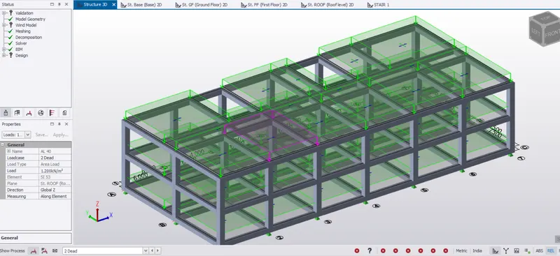
- Click on load- Area load and apply loads to all the slabs.
- Select the load value as 1.2KN/m^2
- Assign the loads to Ground and First floor and roof level.
3D VIEW OF APPLICATION OF FLOOR FINISH (1.2KN/m^2)
APPLYING BRICK WALL LOAD-
- Select Ground Floor.
- In the bottom of the screen there is a draw down panel select DEAD in the panel.
- Click on load- Full UDL and apply loads to all the beams and where there are walls present.
- For ground floor select load value as 16.65 KN/m.
- For First floor select load value as 16.425 KN/m.
- Select line load where there is no beam and wall load are to be assigned.
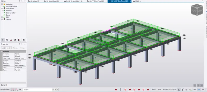
- Apply brick wall load as 4.5KN/m as load of parapet wall on roof.
BRICKWALL LOAD ON GROUND FLOOR (16.65 KN/m.)-
BRICKWALL LOAD ON FIRST FLOOR ( 16.425 KN/m.)-
BRICKWALL LOAD ON ROOF FLOOR (4.5KN/m) -
LIVE LOAD CONSIDERATIONS-
LOADINGS CONSIDERED AS PER IS 875- 1987 (PART 2)-
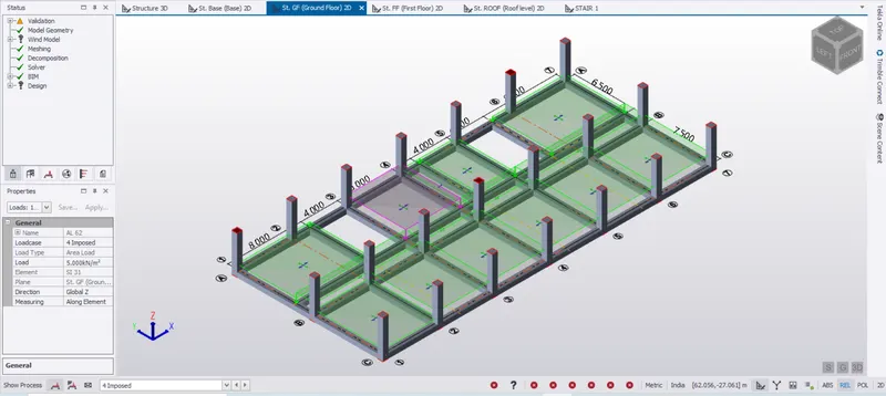
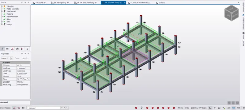
- Meeting Room – 5KN/m^2.
- Office Room– 2.5KN/m^2.
- Reception – 4 KN/m^2
- Toilet – 2KN/m^2.
- Corridor –5KN/m^2.
- Staircase- 5KN/m^2.
- Store – 5KN/m^2.
- Equipment room – 5KN/m^2.
- Lab- 5KN/m^2.
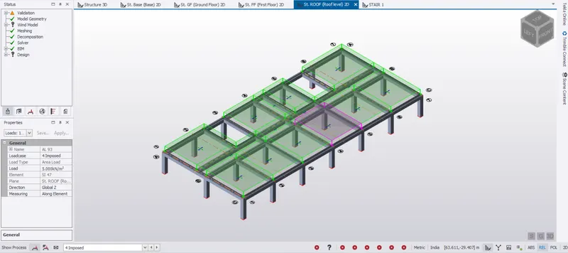
- Flat roof (accessible) – 2 KN/m^2
- Conference Room - 5KN/m^2.
LIVE LOAD ON GROUND FLOOR-
LIVE LOAD ON FIRST FLOOR-
LIVE LOAD ON ROOF FLOOR-
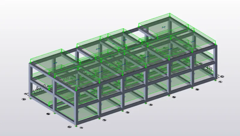
LIVE LOAD ON ENTIRE BUILDING (3D VIEW)-
WIND LOAD CALCULATIONS-
- Basic wind speed = 50m/s
- Terrain category 2
- Life of structure = 50years. (Clause 5.9.1)
- Total length of building (l) = 36 m.
- Total height of building (h)= 7.85 m.
- Total width of building (w)= 16 m
l/w = 36/16 = 2.25.
h/w = 7.85/16 = 0.49.
h/w is smaller than 0.5.
l/w is smaller than 4.
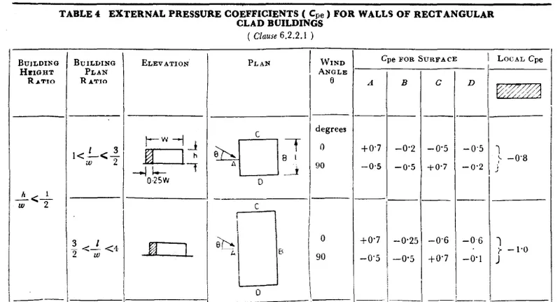
Take building ratio height as (h/w<1/2).
Take building plan ratio as (3/2< l/w < 4).
(TABLE 4 EXTERNAL PRESSURE COEFFICIENTS ( Cpe ) FOR WALLS OF RECTANGULAR CLAD BUILDINGS)
Cpi-
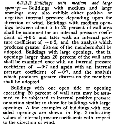
The internal pressure coefficient Cpi is +0.5 , -0.5
STEP 1- Calculation of factors K1, K2, K3, K4.
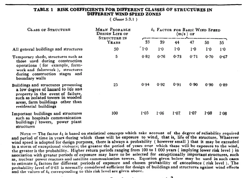
K1= 1 (Probability factor)
For probable life of structure = 50 years and basic wind speed = 50m/s.
(TABLE 1 RISK COEF’FICIENTS.FOR DIFFERENT CLASSES OF STRUCTURES IN DIFFERENT WIND SPEED ZONES ( Clause 5.3.1 )
CLASS OF STRUCTURE AS ALL GENERAL BUILDINGS AND STRUCTRES
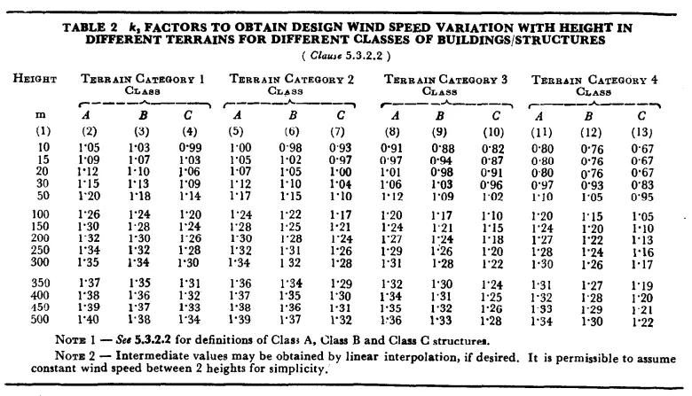
K2 (Terrain category)-
TABLE 2 k2, FACTORS TO OBTAIN DESIGN WIND SPEED VARIATION WITH HEIGHT IN DIFFERENT TERRAINS FOR DIFFERENT CLASSES OF BUILDINGS/STRUCTURES (Clause 5.3.2.2)
CONSIDER FOR 10 M BUILDING AND TERRAIN CATEGORY 2 (CLASS A STRUCTURE)
Hence K2 = 1.0
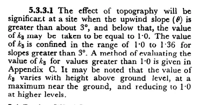
K3 (Topography factor)-
Clause 5.3.3
K3 = 1
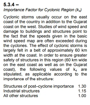
K4 ( Importance factor)-
K4 = 1.15 for industrial structure
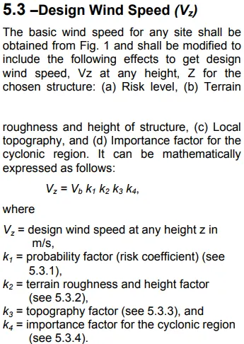
STEP 2- Calculation of design wind speed(Vz)-
Vz= Vb X k1 X k2 X k3 X k4.
Vz= 50 X 1 X 1 X 1 X 1.15.
Vz = 57.5 m/s
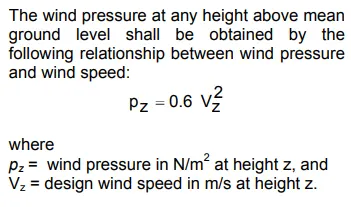
STEP 3- Calculation of design wind pressure (Pz)-
Pz= 0.6 X Vz2
Pz = 0.6 X 57.52
Pz = 1.983 KN/m^2
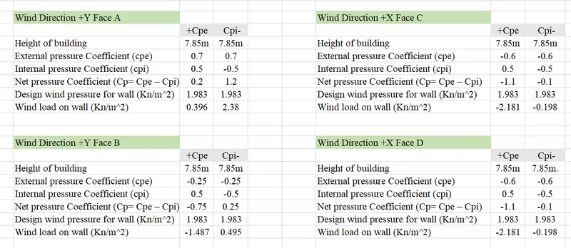
FACE A AND B ARE IN Y-DIRECTION.
FACE C AND D ARE IN X-DIRECTION.
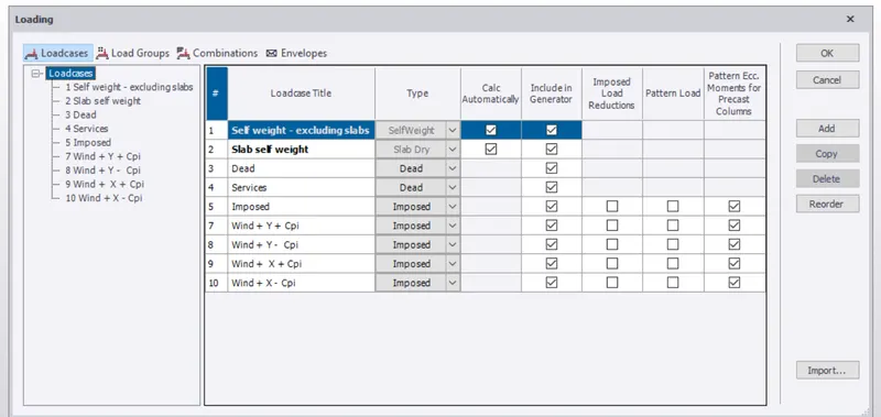
ADDING AND APPLYING ALL THE WIND LOADCASES IN THE MODEL-
- Wind + Y + Cpi
- Wind + Y - Cpi
- Wind + X + Cpi
- Wind + X - Cpi
APPLY ALL THE COMBINATIONS OF WIND LOAD TO THE MODEL.
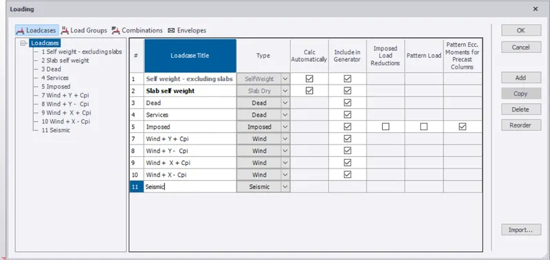
Generating seismic loading based IS codal provisions and zone II-
Seismic load generation-
- On the Load tab, click Seismic Load > Seismic Wizard...
- The Seismic Wizard opens.
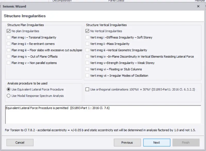
- In the Seismic Wizard, define the necessary parameters for the seismic loading and load cases. To go to the next page, click Next.
- Once you have defined the parameters, click Finish.
- The Combination Generator dialog box opens.
- In the Combination Generator dialog box, define the seismic load combinations.
- Click Finish
SEISMIC WIZARD OPTION-
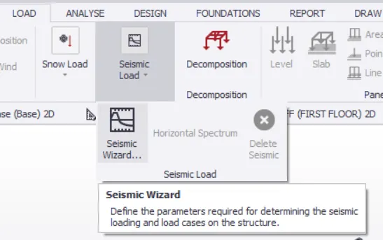
SEISMIC WIZARD- CODE SPECTRA
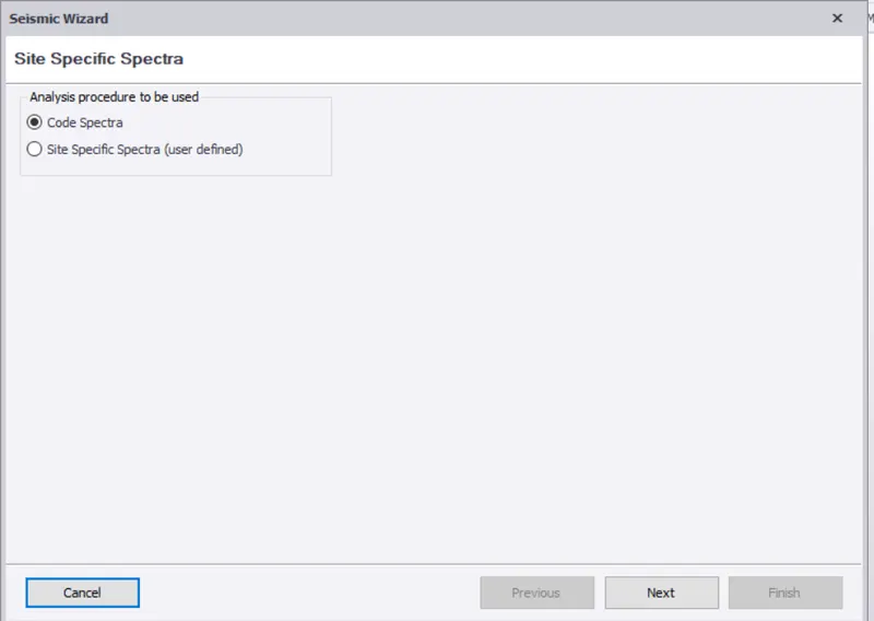
BASE INFORMATION- AUTOMATICALLY GENERATED BY TEKLA SOFTWARE-
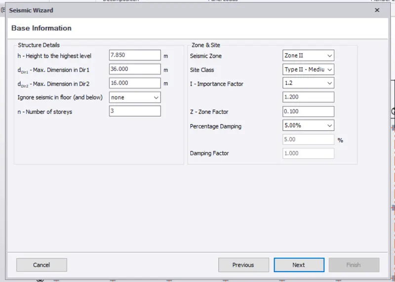
STRUCTURAL IRREGULARITIES- NO PLAN AND STRUCTURAL IRREGULARITY-
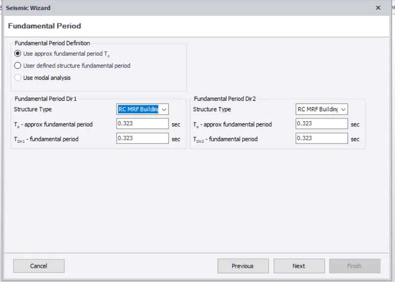
FUNDAMENTAL PERIOD-
Select structure type as RC MRF buildings without any masonry infill
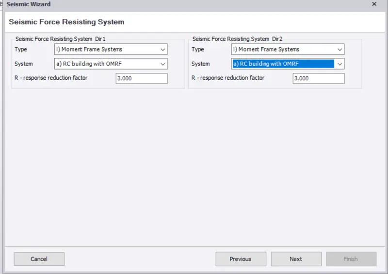
SEISMIC FORCE RESISTING SYSTEM-
Select type as moment frame system and system as RC building with OMRF.
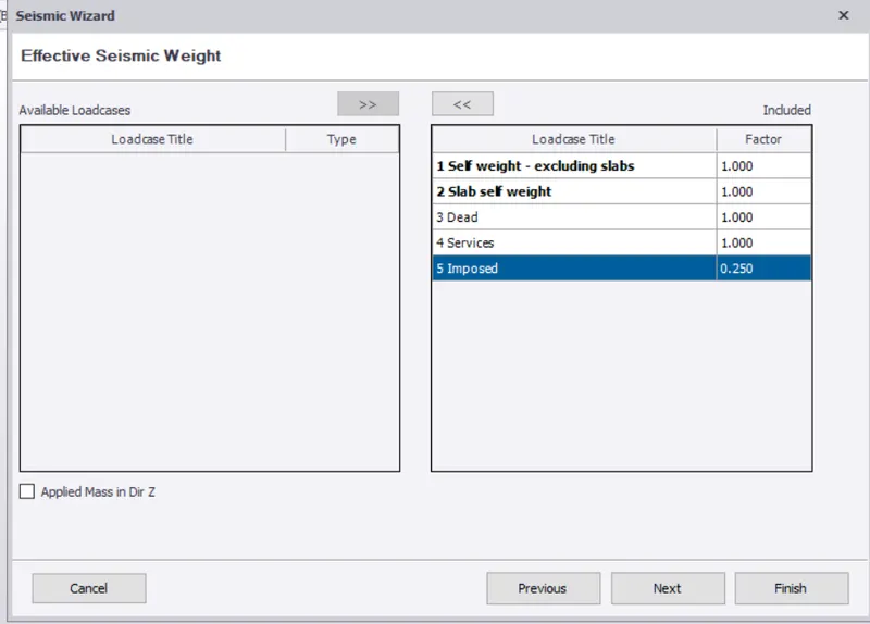
EFFECTIVE SEISMIC WEIGHT-
COMBINATION GENERATOR-
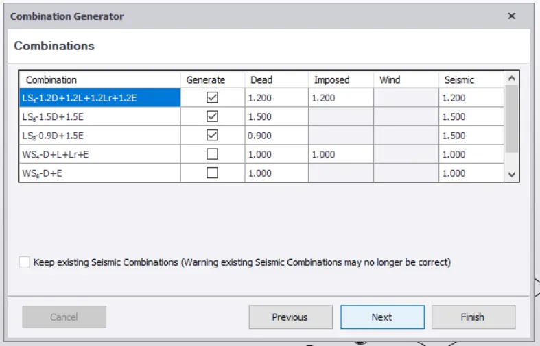
SEISMIC LOAD COMBINATIONS-
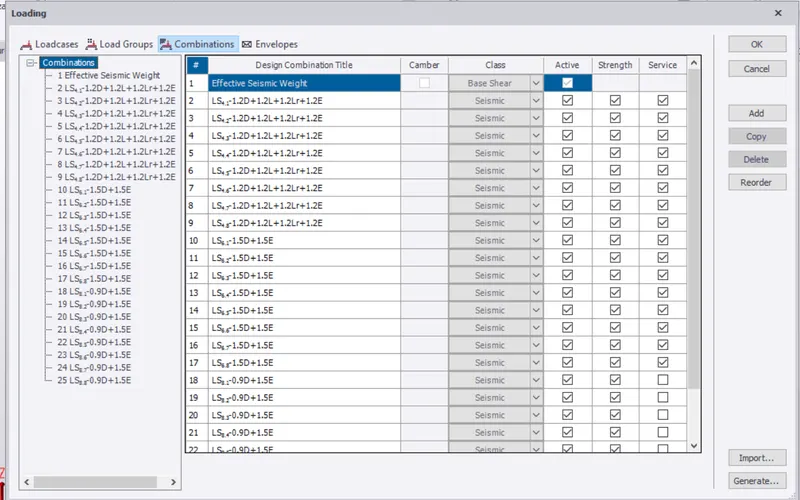
Run the 1st Order analysis and Summarize results-
RUN 1ST ORDER LINER ANALYSIS-
- On the Analyze tab, click 1st Order Linear.
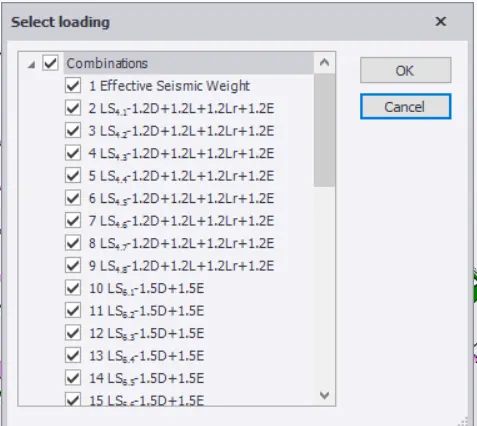
- The Select loading dialog box opens.
- In the Select loading dialog box, select the combinations and loadcases that you want to analyze.
- Click OK.
- Tekla Structural Designer analyzes the model.
- At the end of the analysis process, the Results View and the Results toolbar open, and allow you review the analysis results graphically.
SELECTING LOAD COMBINATIONS-
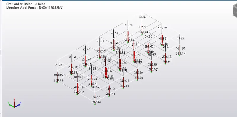
AXIAL FORCE-
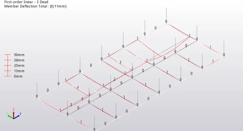
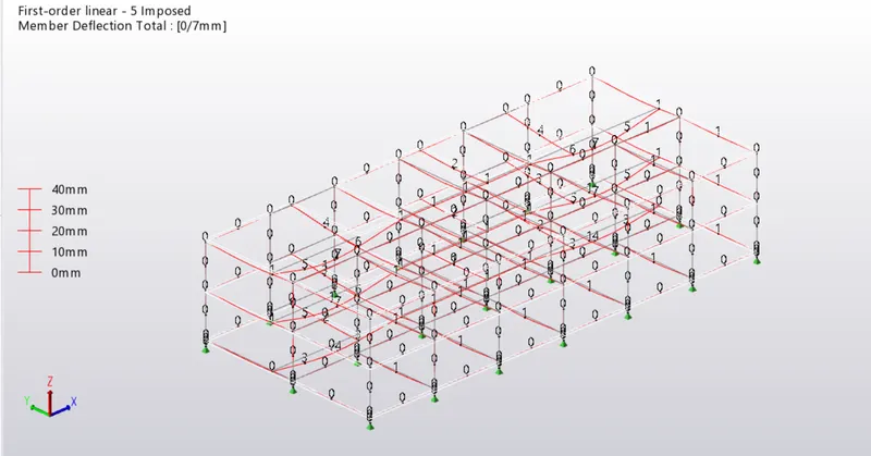
DEFLECTION-
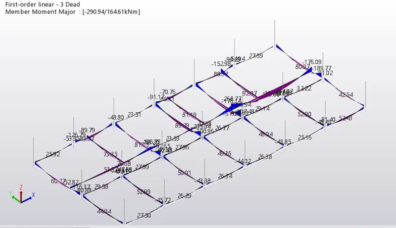
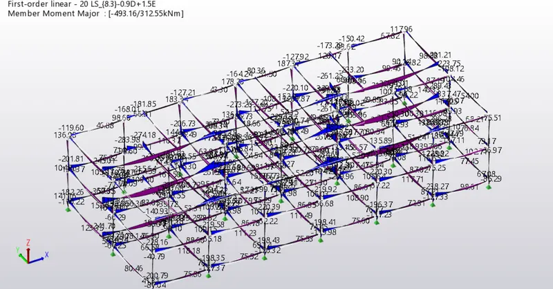
MAJOR MOMENT-
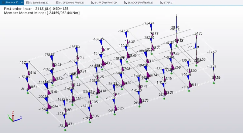
MINOR MOMENT-
DESIGN OF BEAM AND COLUMNS-
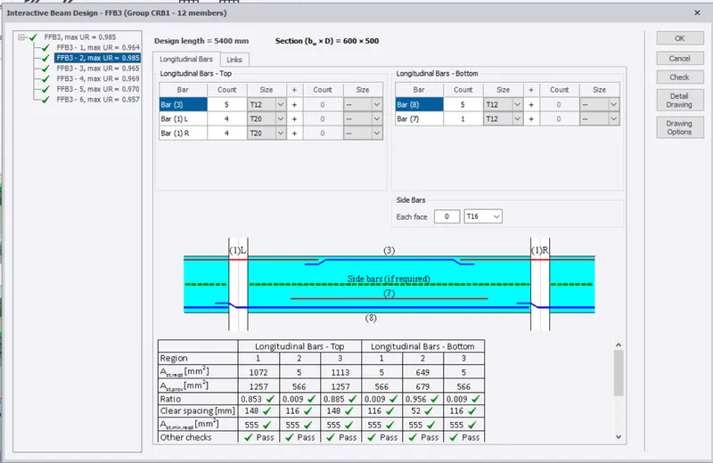
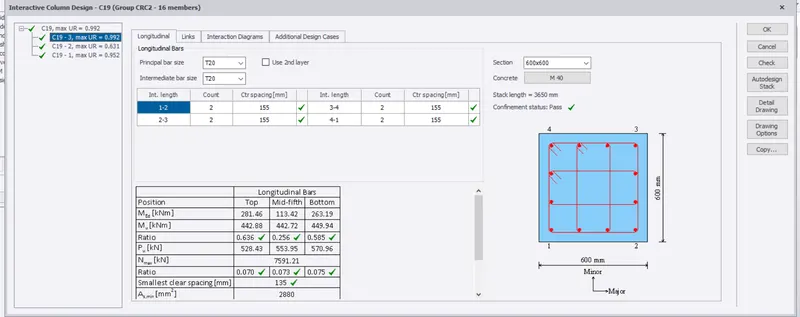
PROCESS OF DESIGN OF BEAM AND COLUMNS ( INTERACTIVE DESIGN)-
- Check weather all the Beams and Columns are assigned at the required place.
- Validate the model and check for any errors.
- If the validation is passed carry out the 1st order Linear analysis.
- In the result view, check the bending moments, shear force, axial force on all the members.
- Right click on Member and select interactive design and then select Static.
- Depending upon the pevious design done the member will pass and fail.
- Where the member is failing check the member and change the aspects such as number of bars, member size etc.
BEAM DESIGN PASSED IN ALL ASPECTS WHEN DESIGNED-
COLUMN DESIGN PASSED IN ALL ASPECTS WHEN DESIGNED-
DESIGN OF SLAB-
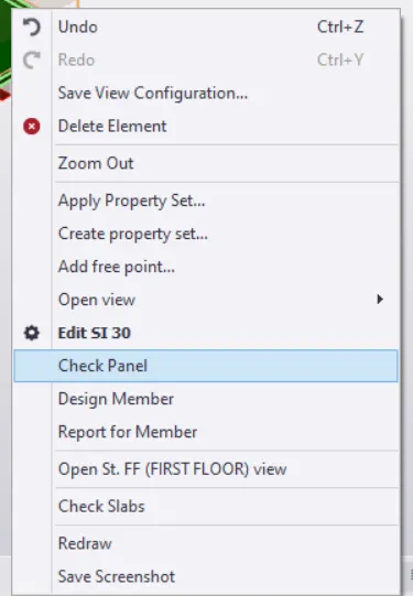
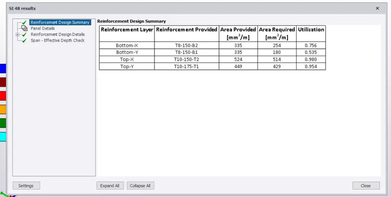
CHECKING OF SLAB PANEL OPTION-
SLAB DESIGNED SAFELY-
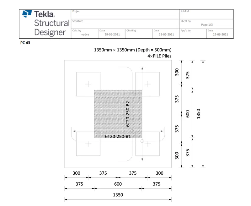
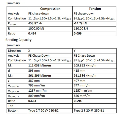
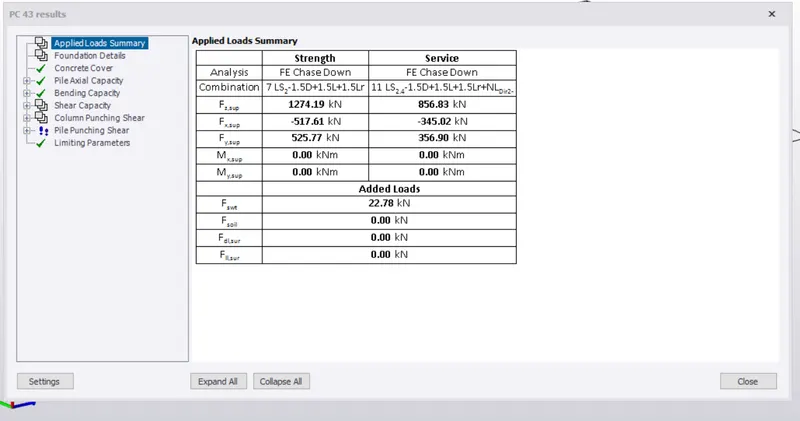
DESIGN OF PILE-
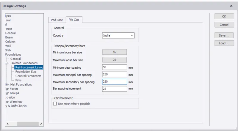
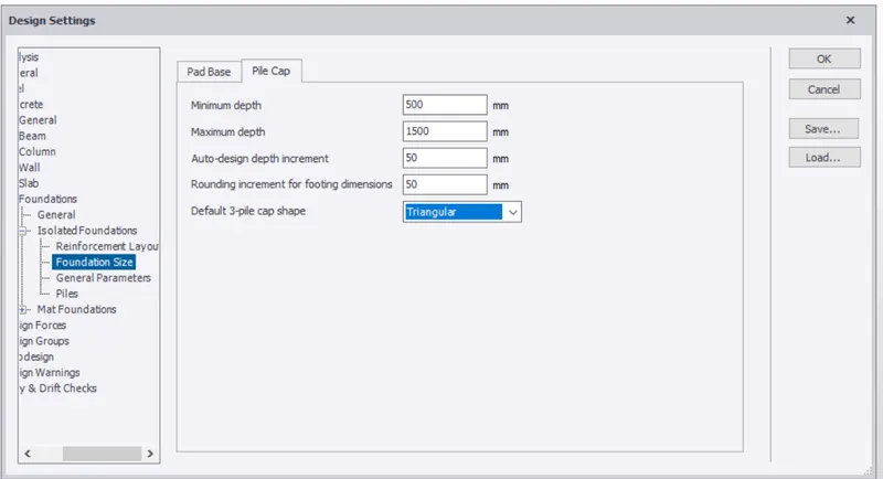
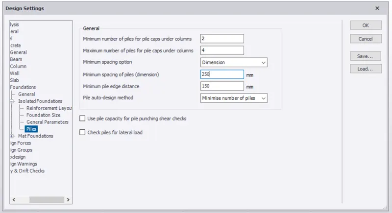
CHANGING THE SETTINGS OF PLIE FROM SETTINGS TAB IN FOUNDATION-
REINFRCEMENT LAYOUT SETTINGS OF PLE CAP-
FOUNDATION SIZE SETTINGS OF PLE CAP-
PILE DESIGN-
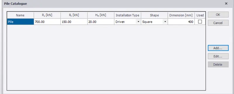
DEFINING OF PILE PROPERTIES FROM CATLOG-
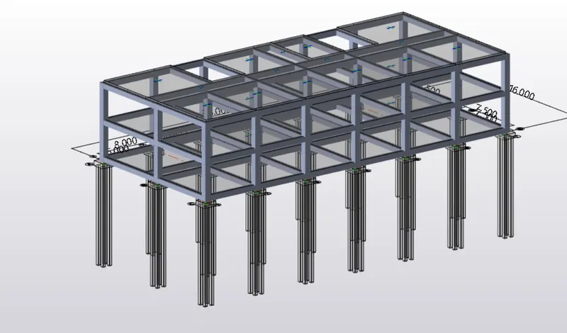
PLACING OF PILES BELOW THE COLUMN AND DESIGN OF PILE-
- On the Foundations tab select the option Pile cap column and place the piles accordingly below each column and design the pile
REPORT GENERATION-
PROCEDURE FOR GENERATING A REPORT IN TEKLA-
- Open the previously created R.C.C model.
- Run the 1st oder Analysis.
- Go to the report tab and select Solver Model Data.
- Apply the parameters for the data for which report have to be generated.
- Select Show report