Projefct 1_Comparative study of different storey buildings for Seismic forces
PROJECT 1- Comparative study of different storey buildings for Seismic force.
THE TABLE SHOWS THE PROPERTIES OR CHARACHTERISTICS OF BUILDING TO BE MODELLED USING ETABS.
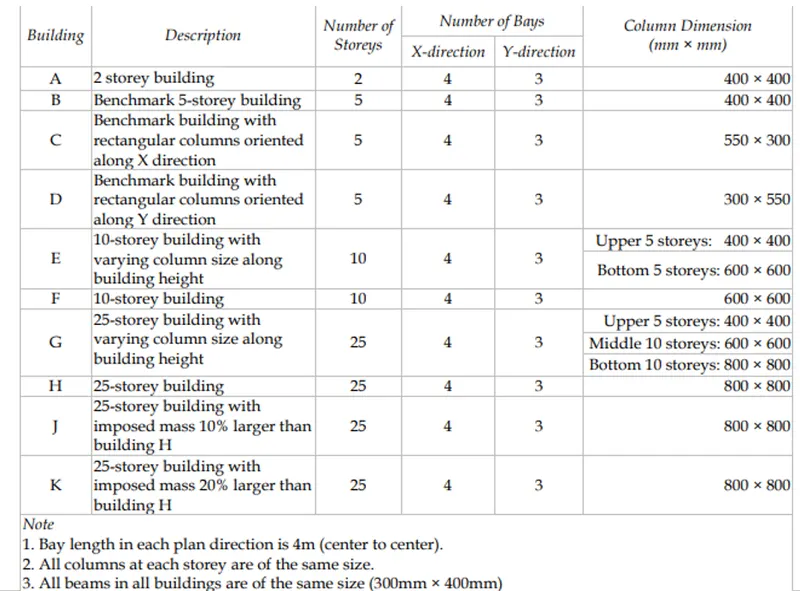
AIM- TO MODEL THE BUILDINGS AND COMPARE DIFFERENT PARAMETERS OF THE BUILDINGS BY CALCLATING THE MODES.
Detailed Procedure for modelling building number 'A'-
DATA FOR MODELLING FOR BUILDING 'A'-
- Number of storeys = 2.
- Number of bays in X direction =4
- Number of bays in Y direction =3.
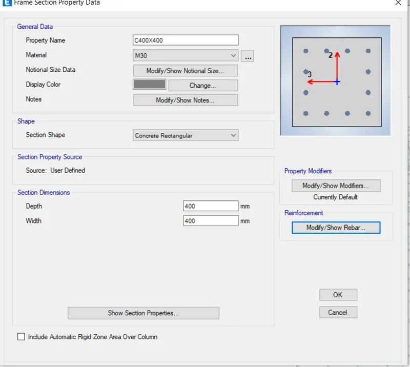
- Size of column = (400 X 400) mm.
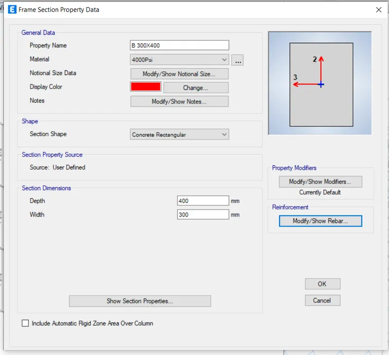
- Size of beam= ( 300 X 400 )mm.
- Grade of concrete =M30
- Grade of steel reinforcement bars= Fe415
- Live load= 3KN/M^2
- Height of storey = 3m
- Height of plinth = 1.5m
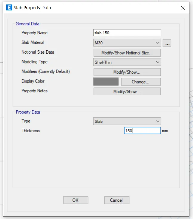
- Thickness of slab= 150mm.
STEPS
STEP-1
- Open ETABS 2019.
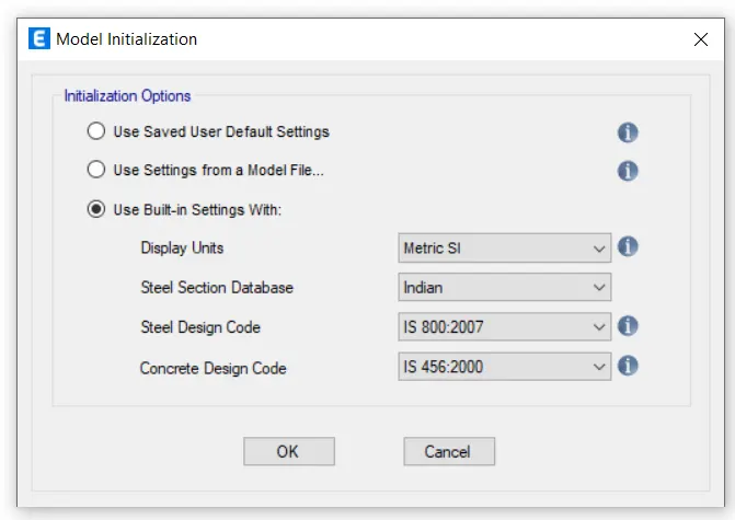
- Go to file menu and select new model, a pop up window of model initialization will be opening.
- Select use built in settings.
- Select display units as Metric SI, Steel section data base as Indian, Steel design code as IS 800:2007, concrete design code as IS 456:2000.
- Select OK.
STEP-2
- A new window of new model quick templates will be appearing.
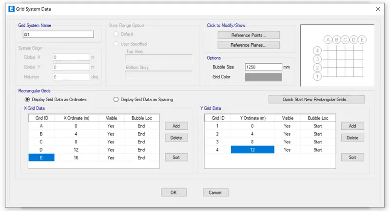
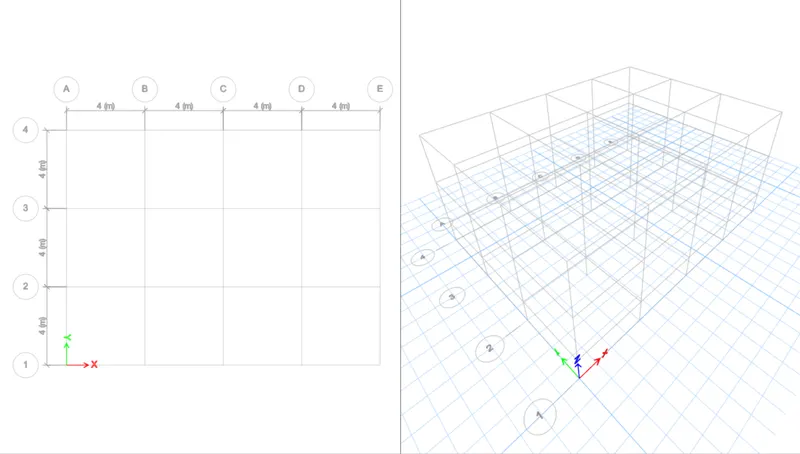
- Select the grids and customise grids.
- Set X grid data at spacing of 4m, and number of grids is 5.
- Set Y grid data at spacing of 4m, and number of grids is 4.
- Click OK
STEP-3
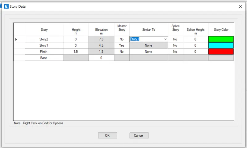
- Now select the option custom story data and select edit storey data.
- Select plinth height as 1.5m, and height of storey as 3m.
- Add storey and make total number of story as 2.
- Keep master storey 1 as yes.
- Click OK.
STEP-4
- Defining the properties of elements.
- Go to define and select material properties.
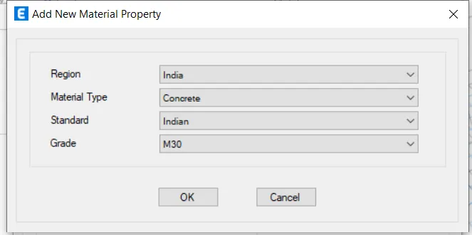
- Select grade of concrete as M30.
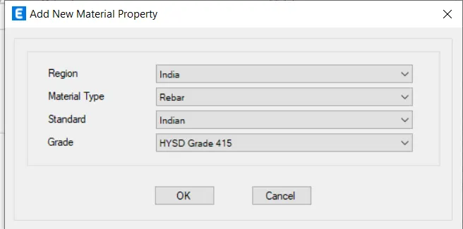
- Select steel as HYSD 500and HYSD 415 steel.
CONCRETE DATA
STEEL DATA-
STEP-5
- Defining beam column properties.
- Go to define tab, section properties and frame sections.
COLUMN DETAILS-
BEAM DETAILS-
STEP-6
- Defining slab properties.
- Go to define tab, section properties and slab sections.
SLAB DETAILS-
STEP-7
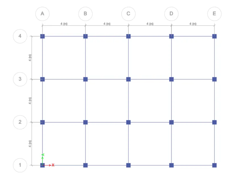
- Drawing of beams and columns.
- In the left side of the draw panel select the option quick draw column.
- Place columns on the grids
- For drawing of beams select the option quick draw beams in the draw panel and place the beams.
DRAWING OF BEAMS AND COLUMNS-
STEP-8
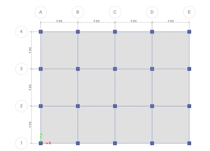
- Drawing of slab.
- In the left side of the draw panel select the option quick draw floor.
- Place slabs between the grids.
DRAWING OF SLABS-
STEP-9
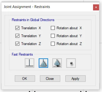
- Change the base connections.
- Go to the base view in the plan.
- Select the base view.
- Select assign tab, joints, restraints and select pinned connection.
STEP-10
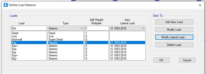
- Assigning loads on the structure.
- Select define, load patterns and enter the load patterns as shown in the image.
STEP-11
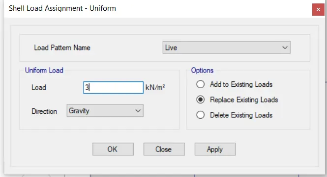
- Assigning live loads.
- Go to assign tab and select shell loads , uniform and assign load of 3KN/M
STEP-12
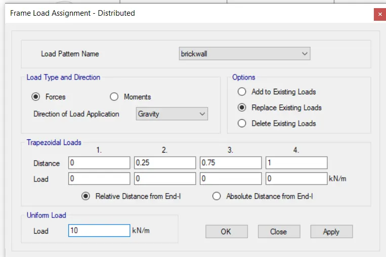
- Assigning load on beam as brick wall load.
- Apply load of 10KN/M^2.
STEP-13
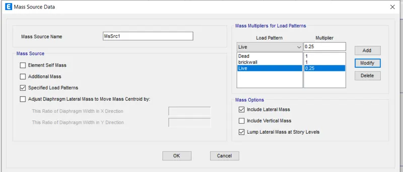
- Assigning mass source to model.
- Go to define tab select mass source and enter the details as shown in the image.
STEP-14
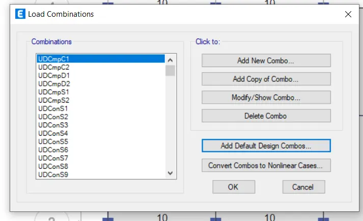
- Generating load combinations.
- Select define tab- load combinations- add default- concrete frame- convert to editable.
- Enter data as shown in the image.
STEP-15
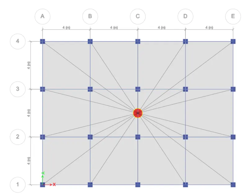
- Assigning diaphragms to the model.
- Go to assign tab select shell, select diaphragms and select D1.
- Apply the diaphragms.
STEP-16
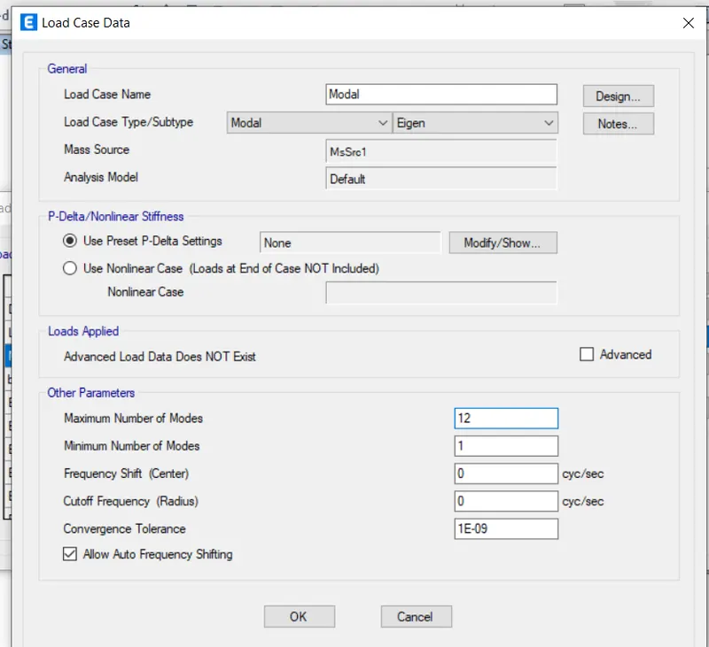
- Creating modal analysis.
- Go to define tab-modal cases- modify.
- Enter the data as shown in the image.
STEP- 17
- Checking the model.
- Go to the analyse tab and select option check model.

STEP-18
- Running the analysis
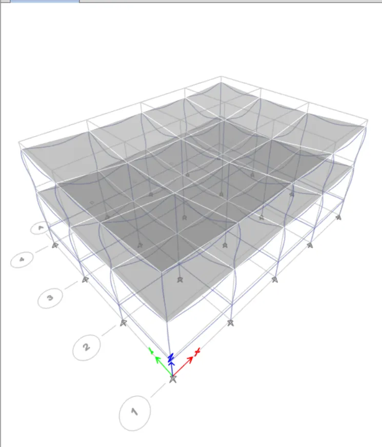
STEP-19
- Modal results.
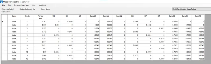
- Select display- show tables- structure output- modal information- modal participation ratios.
- A table will be appearing on the screen.
Modelling and Design of Buildings B, C, D, E, F, G, H, J, K-
- The design and modelling of the buildings are done same as per the procedure and steps followed while designing and modelling building ‘A’.
- The steps are mentioned clearly that are performed.
- The changes in the data of the buildings are adopted and buildings B, C, D, E, F, G, H, J, K are modelled and designed.
RESULTS-
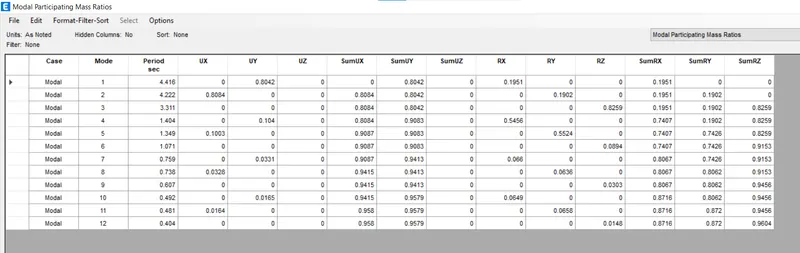
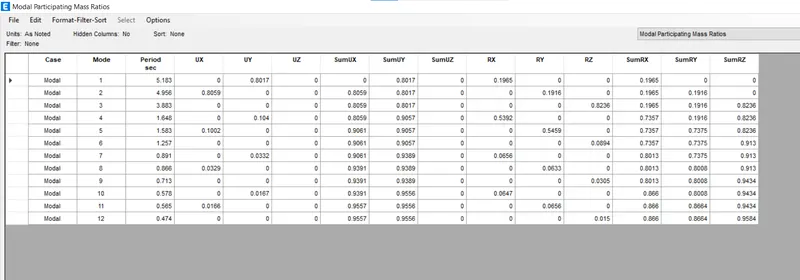
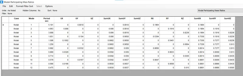
TABLES OF MODAL PARTICIPATING MASS RATIOS-
BUILDING 'A'-
BUILDING 'B'-
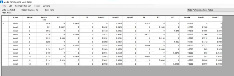
BUILDING 'C'-
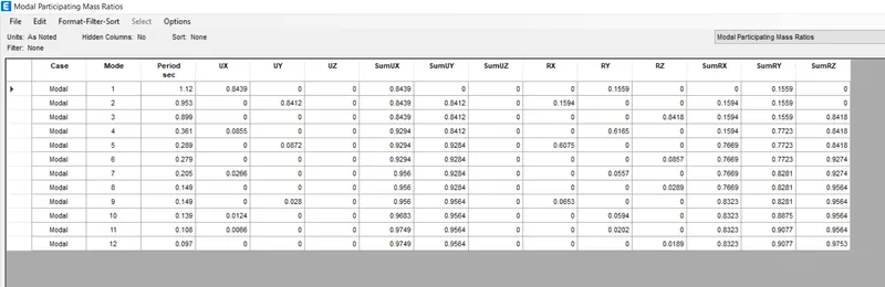
BUILDING 'D'-
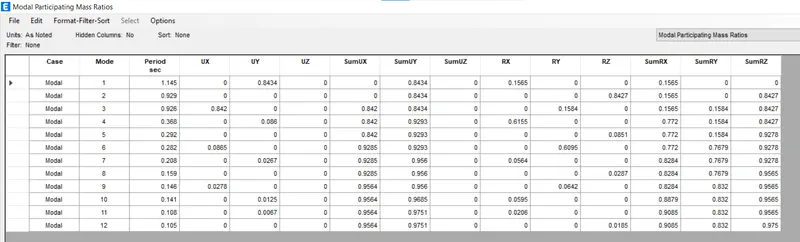
BUILDING 'E'-
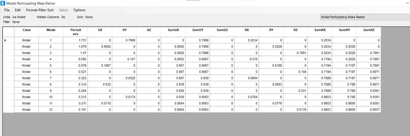
BUILDING 'F'-
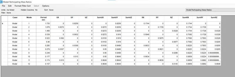
BUILDING 'G'-
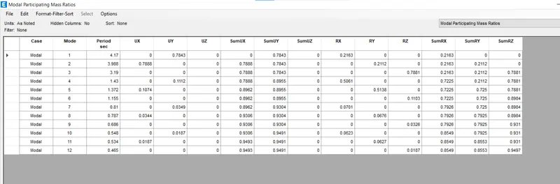
BUILDING 'H'-
BUILDING 'J'-
BUILDING 'K'-
AIM 1-
Effect of stiffness on T- Compare fundamental natural periods of Buildings E, F as well as G and H. Why there is marginal or significant difference in the fundamental natural periods.
Time period for Buildings-
- Building E is 1.731.
- Building F is 1.735.
- Building G is 4.17.
- Building H is 4.416.
The natural periods of building E and F are almost same as the buildings have same height. The only difference in them is the size of columns.
The buildings G and H have more time period because the height of the building is more. Due to the height of building it has sufficient ductility and the time period is more for G and H buildings. The size of Columns in G and H building is more than E and F hence there is more flexibility in the building.
AIM 2-
Compare fundamental natural periods of buildings H, J and K, Have the buildings become more flexible or stiff due to change in the mass.
Time period for Buildings-
- Building H is 4.416.
- Building J is 5.183.
- Building K is 5.191.
Taller buildings are more flexible and have larger mass, and therefore have a longer T. For building J and K load has been increased by 10% and 20% so the building has more time period T. The buildings have become more flexible due to change in mass.
AIM 3-
Effect of building height on T-How does the fundamental natural period of building A, B, F and H change with change in building height.
Time period for Buildings-
- Building A is 0.363.
- Building B is 1.036.
- Building F is 1.735.
- Building H is 4416.
Taller buildings are more flexible and have larger mass, and therefore have a longer T. On the contrary, low- to medium-rise buildings generally have shorter T (less than 0.4 sec). As the building A and B has 2 and 5 number of floors its time period is less, where as F and H buildings are 10 and 25 storey their time period T is more.
AIM 4-
Effect of column orientation- How does the fundamental natural periods of Building B, C and D change in column orientation.
Time period for Buildings-
- Building B is 1.036.
- Building C is 1.12.
- Building D is 1.415
The change in column orientation increases the time period of buildings. Columns should be oriented in longer direction to increase the time period.
Effect of Flexural stiffness of structural elements on mode shapes-
- The overall lateral translational mode shapes depend on the flexural stiffness of beams relative to that of adjoining columns. The fundamental mode shape of buildings changes from flexural-type to shear-type as beam flexural stiffness increases relative to that of column.
Effect of Axial Stiffness of Vertical members on mode shapes-
- Mode shapes depend on axial stiffness of vertical members in a building (i.e., of columns or structural walls).
- Small Axial Stiffness causes significant axial compressive and tensile deformation in columns in addition to single or double curvature flexural deformations.
- Additional Axial Deformation changes the fundamental mode shape from shear-type to flexural type, particularly in tall buildings.
- Pure Flexural Response is not desirable because of large lateral sway, particularly at higher floors.
Effect of Degree of Fixity at column bases on mode shapes-
- Highly Flexible soils make column bases as good as hinged, and rocky layers below as good as fixed.
- Lack of Rotational Fixity at the Column Base (hinged condition) increases the lateral sway in the lower storey than in the higher storey, and the overall response of the building is more of shear-type.
- On the other hand, full rotational fixity at the column base restricts the lateral sway at the first storey and thus, induces initial flexural behaviour near the base.
- The overall response of the building is still of shear-type due to flexural stiffness of beams.