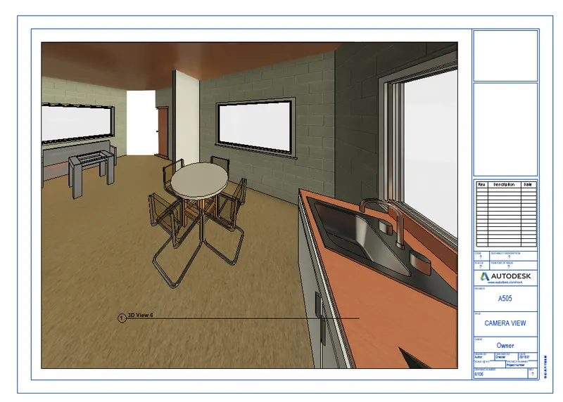
3D Creation of Celing, Roof, Architectural plan, Structural plan, Sectional view, Elevation view and Camera specific view for a house plan using REVIT
PROJECT-1
- Based on the project saved from Week 3, proceed from the First Floor Level. Model a Ceiling from the architecture tab above the walls at the first-floor level
- Open a ceiling plan view.
- Click Architecture tab Build panel (Ceiling).
- In the Type Selector, select a ceiling type.
- Place a ceiling.
- Click Modify / Place Ceiling tab Ceiling panel (Sketch Ceiling).
- Use tools in the Draw panel of the ribbon to sketch a closed loop that defines the ceiling boundary.
- On the ribbon, click (Finish Edit Mode).
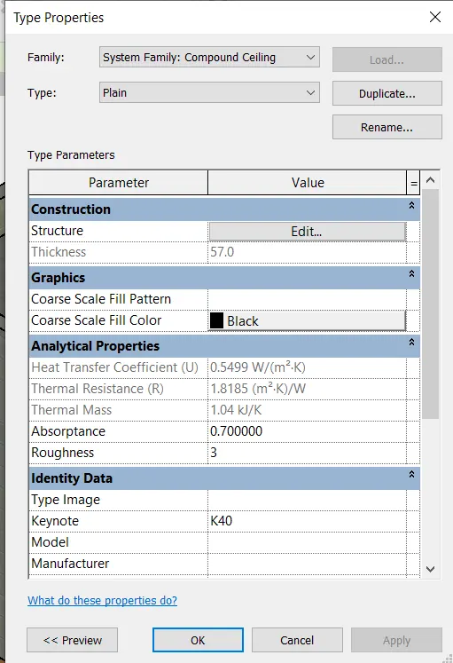
- The thickness of ceiling is 57 so adjust the height of ceiling to 2943 from the properties option in the left of the screen by clicking every part of the ceiling.
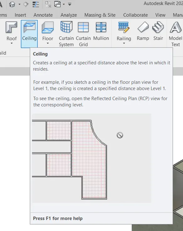
CEILING PROPERTIES
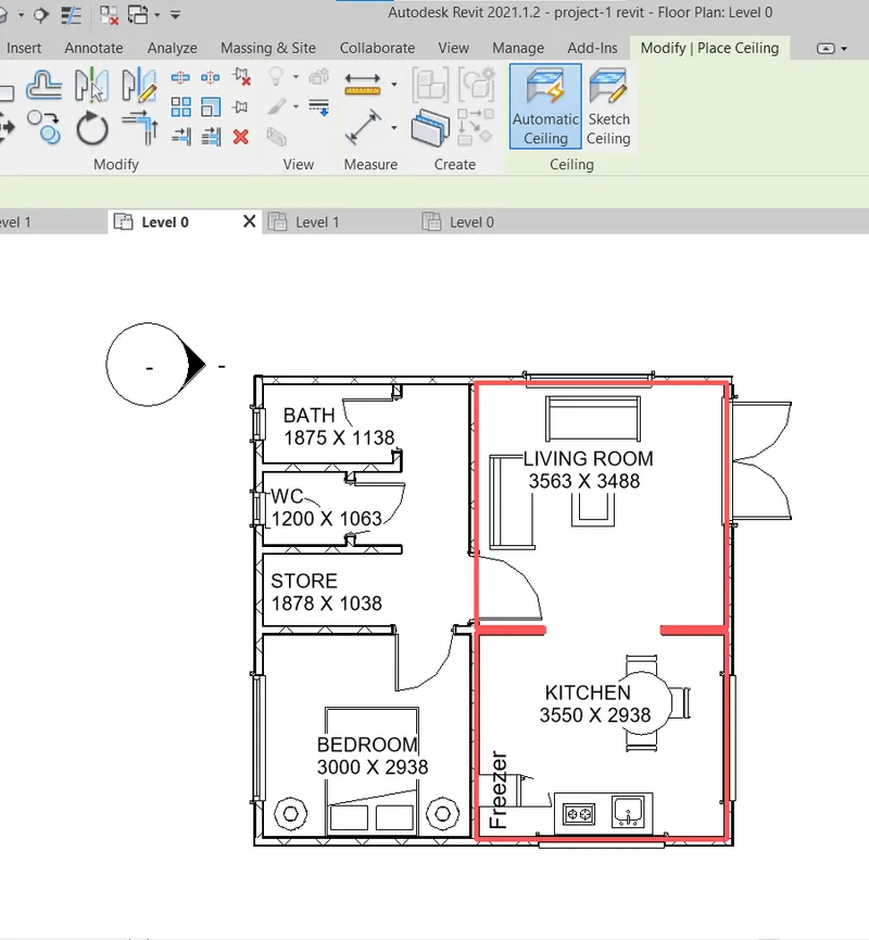
SELECT OPTION- AUTOMATIC CEILING.
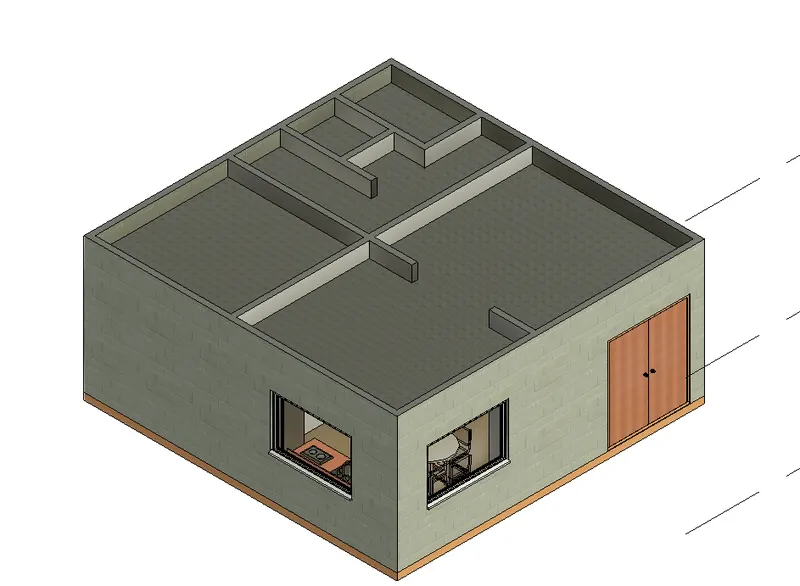
FINAL IMAGE OF CEILING.
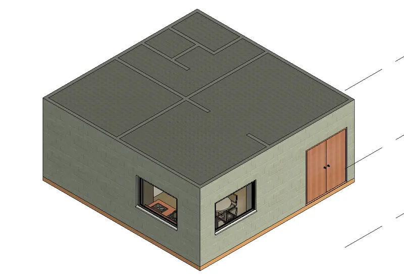
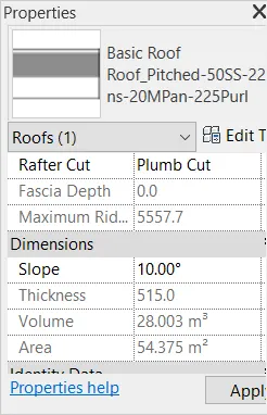
- Model a roof above the ceiling by selecting the footprints of the ceiling. Using the adjustment toolbars appearing on-screen adjust the roof slope to 10 degrees.
Creation of Roof using Footprint-
- Display a floor plan view or a reflected ceiling plan view.
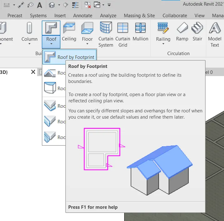
- Click Architecture tabBuild panelRoof drop-down (Roof by Footprint).
- On the Draw panel, select a sketch or pick tool. To edit roof properties before sketching, use the Properties palette.
- Sketch, or pick, a closed loop for the roof.
- Specify slope defining lines. To change the slope definition of a line, select the line and, on the Properties palette, click Defines Roof Slope. You can then change the slope value.
- When a roof line is set to slope defining, this symbol appears adjacent to it.
- Click (Finish Edit Mode), and then open a 3D view
ROOF BY FOOTPRINT OPTION-
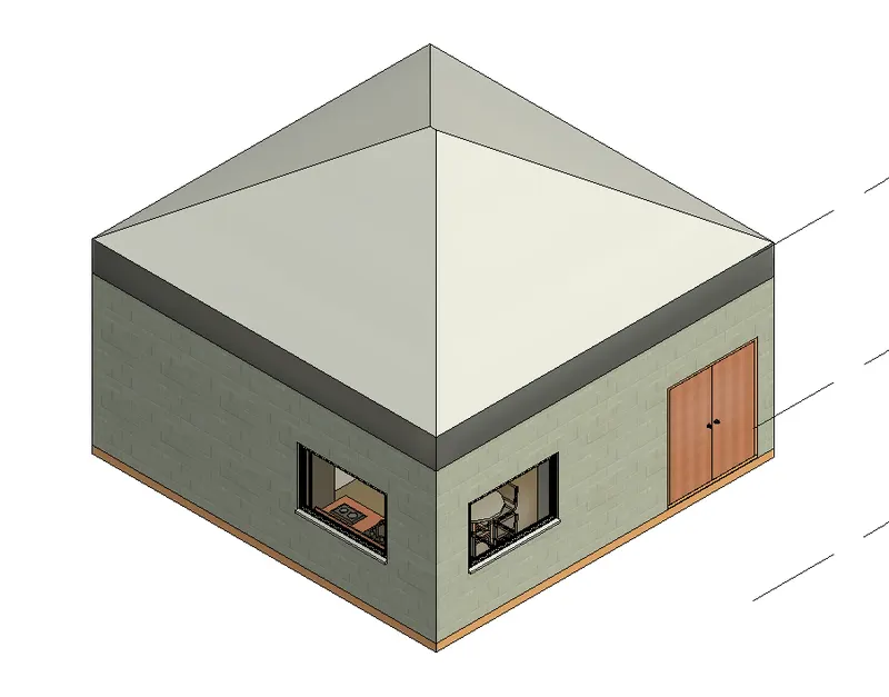
ADJUSTING SLOPE OF ROOF TO 10 DEGREES.
ROOF WITH 10 DEGREES SLOPE-
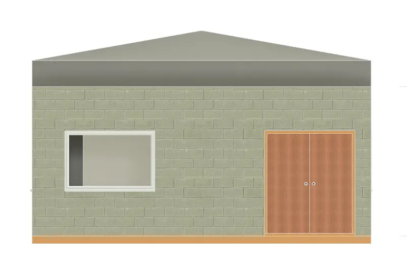
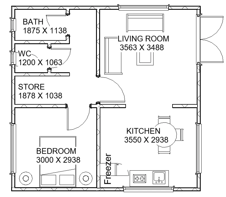
- Using the file saved from weeks 2 to 4, create plan views for ground floor level and first-floor level including all the walls, floors, and components. Separate them to architecture and structural plans.
ARCHITECTURE PLANS-
- Create walls in the architectural tab.
- Select suitable type of wall.
- Select wall finish for decoration of walls.
- Place windows and doors in the architectural tab and place it to the desired locations.
- Add furniture to the building using the load family from insert tab.
- Load the suitable families and add the components and units
FIRST AND SECOND FLOOR ARCHITETRAL PLAN.
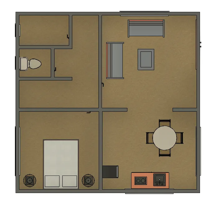
REALISTIC ARCHITECTURAL VIEW-
STRUCTURAL PLAN-
Drawing of the column-
- Click Architecture tab Build panel Column drop-down (Column: Architectural).
- On the Options Bar, specify the following:
- Rotate after placement. Select this option to rotate the column immediately after placing it.
- (3D views only) Select a level for the column's base. For plan views, the view's level is the base level for the column.
- This setting draws the column upward from its base. To draw the column downward from its base, select Depth.
- Level/Unconnected. Select a level for the top of the column, or select Unconnected and specify the column height.
- Room Bounding. Select this option to designate the column as room-bounding before you place it.
- Click in the drawing area to place the column.
- If you need to move the column, select it and drag it to a new position.
DETAILS OF COLUMN-
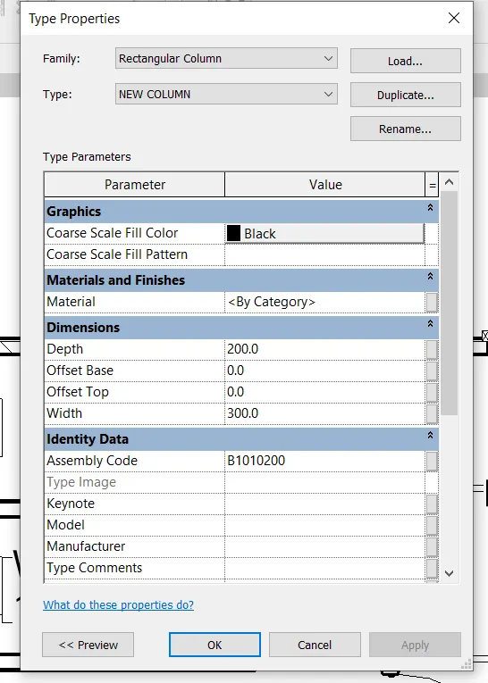
PLACING OF COLUMNS-
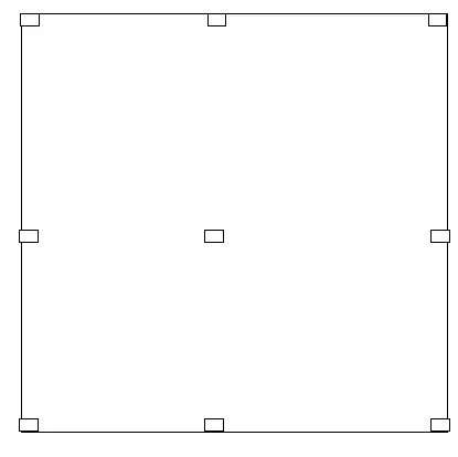
DRAWING THE BEAM-
- Click Structure tab Structure panel (Beam).
- On the Options Bar:
- Specify a Placement Plane if a work plane other than the current level is required.
- Specify a Structural Usage for the beam.
- Select 3D snapping to snap to other structural elements in any view. You can sketch beams outside of the current work plane. For example, when 3D snapping is enabled, roof beams will snap to the tops of columns, regardless of elevation.
- Select Chain to continuously place beams in succession. The second click in placing a beam will be the start of the next beam. Press Esc to complete chain placing beams.
- Sketch the beam by clicking the start point and endpoint in the drawing area.
- Using annotate toolbar add dimensions to all the walls and floors with reference to the longitudinal and transverse grids created in the project file.
Drawing of grids-
- Navigate to Architecture > Grid or Structure > Grid. Now click once at the start and again at the end of the grid you wish to set up. This should snap to a vertical. Set up however many you need, at approximate spacings this way. Revit labels them 1, 2, 3... Now draw a horizontal grid line. Double click the number and enter the letter "A" instead and hit Enter. Now when you create further horizontal grids they will be labelled A,B,C... Now select each and modify the spacing between them.
MARKING OF GRIDS-
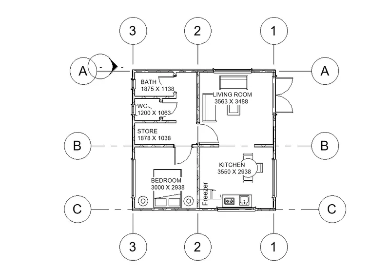
DIMENSIONS W.R.T COLUMNS-
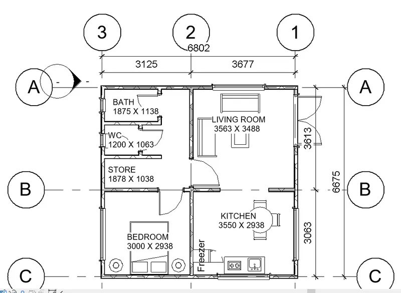
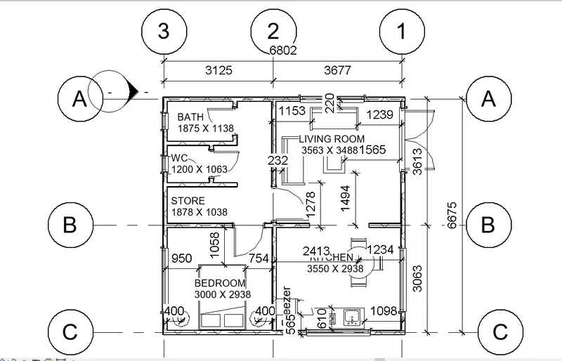
DIMESNIONS W.R.T FURNITURE AND COLUMNS-
- Create a sheet template from the view tab and adjust the parameters on the sheet to add appropriate views.
CREATEING SHEET TEMPLATE-
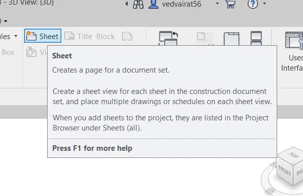
- Go to the view tab.
- Select sheet.
- A popup window will be appearing on the screen.
- Select the sheet template or customize according to the user needs.
SHEET TEMPLATE OPTION-
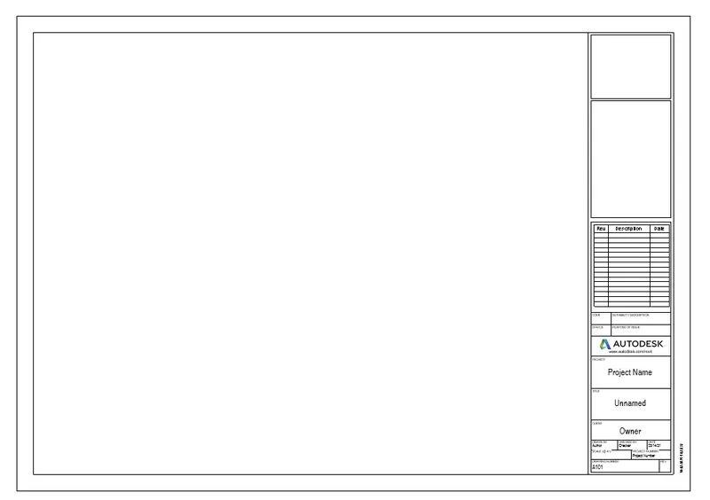
BLANK SHEET TEMPLATE-
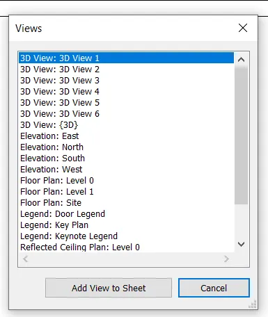
PLACING OF VIEWS ON TEMPLATE-
FINAL PLACEMENT OF VIEWS ON SHEET TEMPLATE
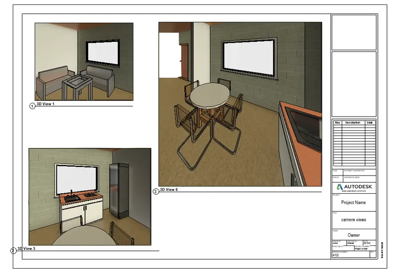
- Using the elevation tab create the elevation views, looking at your building from East, North, South, and West
EAST ELEVATION-
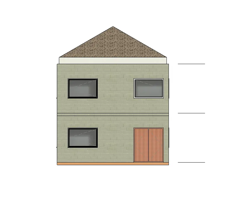
WEST ELEVATION-
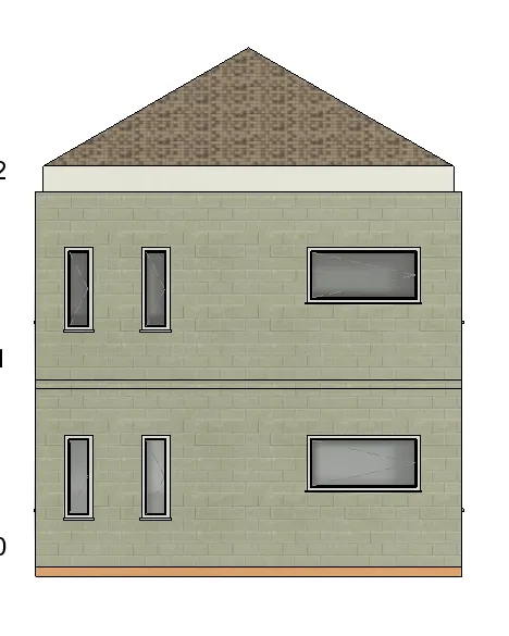
NORTH ELEVATION-
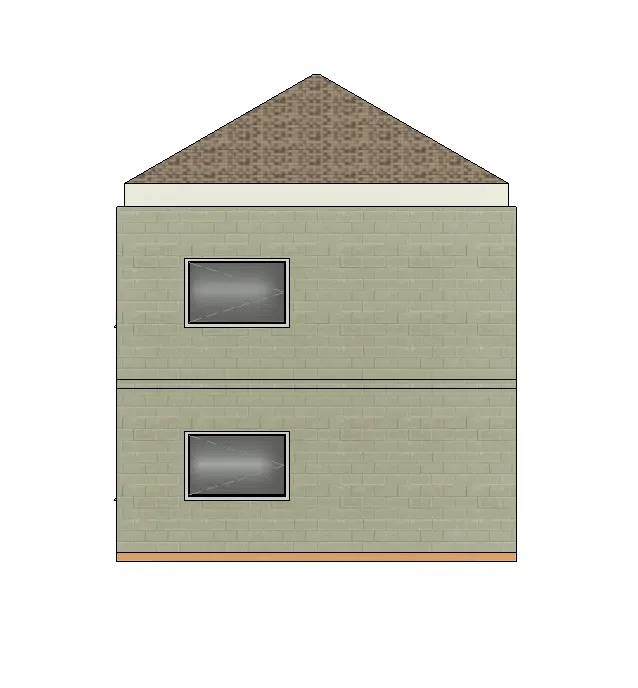
SOUTH ELEVATION-
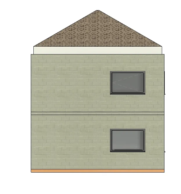
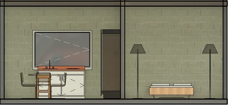
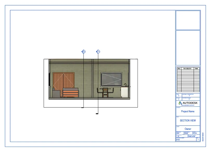
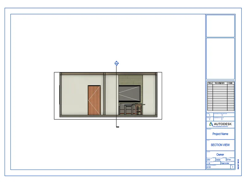
- Produce section cut through each room either cutting across longitudinally or in a transverse direction.
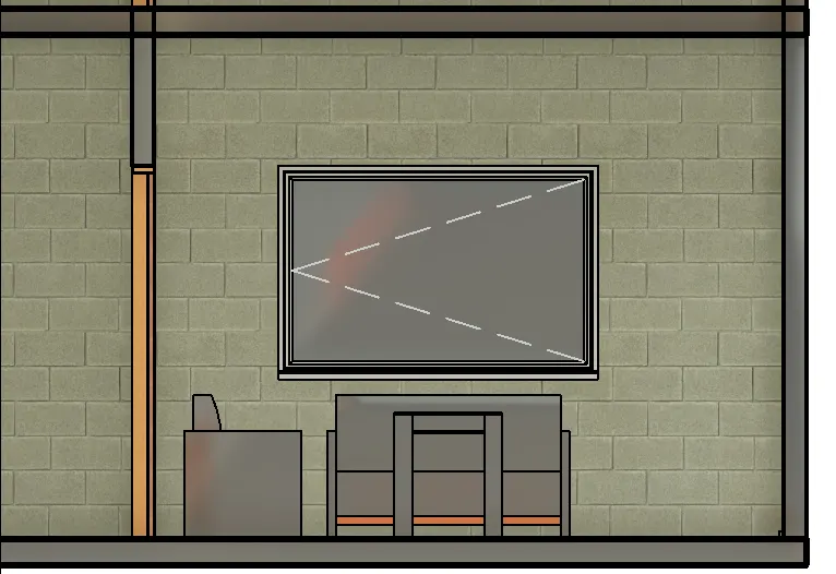
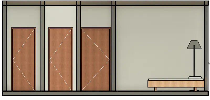
Creation of section view-
- Click View tab Create panel (Section).
- Place the cursor at the starting point of the section, and drag through the model or family.
- Click when you reach the end point of the section.
- The section line and the crop region appear and are selected.
- If desired, resize the crop region by dragging the blue controls. The depth of the section view changes accordingly.
- Click Modify or press Esc to exit the Section tool.
- To open the section view, double-click the section header, or select the section view from the Sections grouping of the Project Browser.
- The section view changes when the design changes or the section line is moved.
SECTION OF KITCHEN AND BEDROOM-
SECTION OF LIVING ROOM-
SECTION OF STORE, BATH AND BEDROOM-
- Classify the views, Plan Views, Section Views, and Elevation views to either Design or Documentation category using Properties browser.
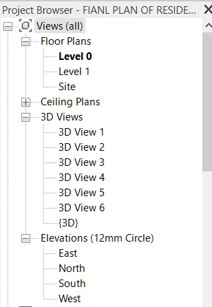
VIEWS OF RESIDENTIAL BUILDING.
- Go to the property browser in the left of the screen.
- Different views are available in the section of roject browser.
- Click on any of the view created.
- To open the Project Browser, click View tab Windows panel User Interface drop-down Project Browser, or right-click anywhere in the application window and click Browsers Project Browse.
- Using the sheet template produced create multiple sheets.
CREATEING SHEET TEMPLATE-
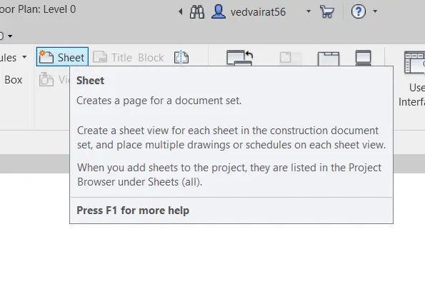
- Go to the view tab.
- Select sheet.
- A popup window will be appearing on the screen.
- Select the sheet template or customize according to the user needs.
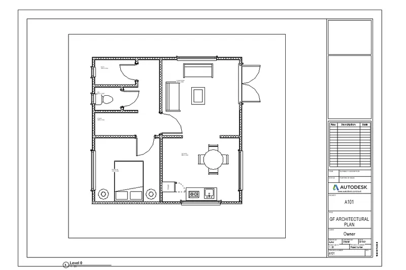
a. A 101- Ground Floor Architecture Plan
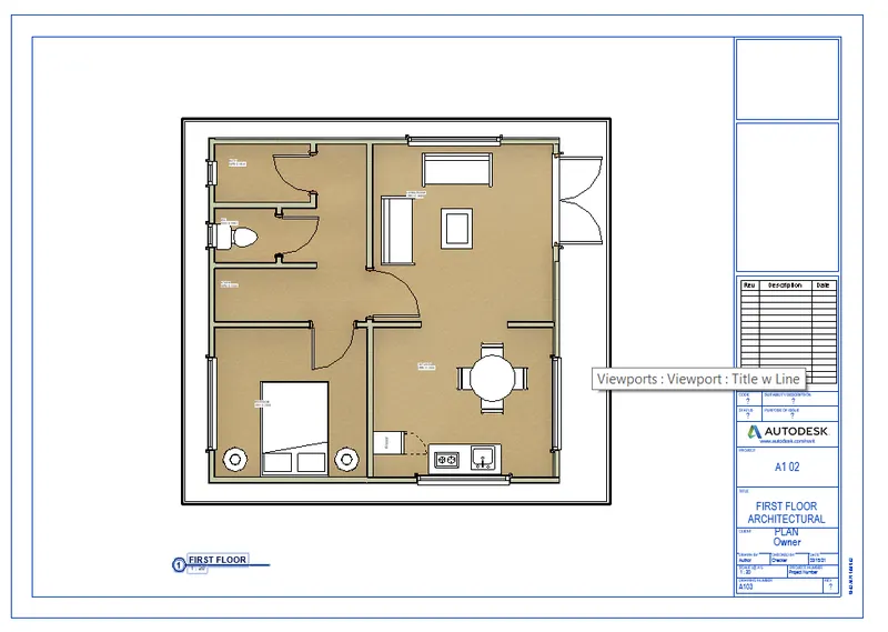
b. A 102- First Floor Architecture Plan
c. A 103- Roof Plan
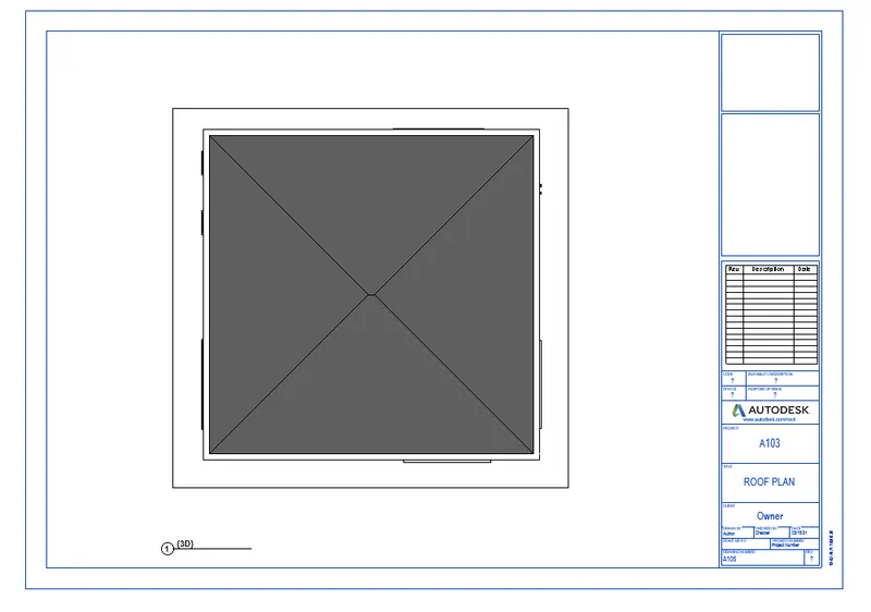
d. S 101- Ground Floor Structural Plan
e. S 102- First Floor Structural Plan
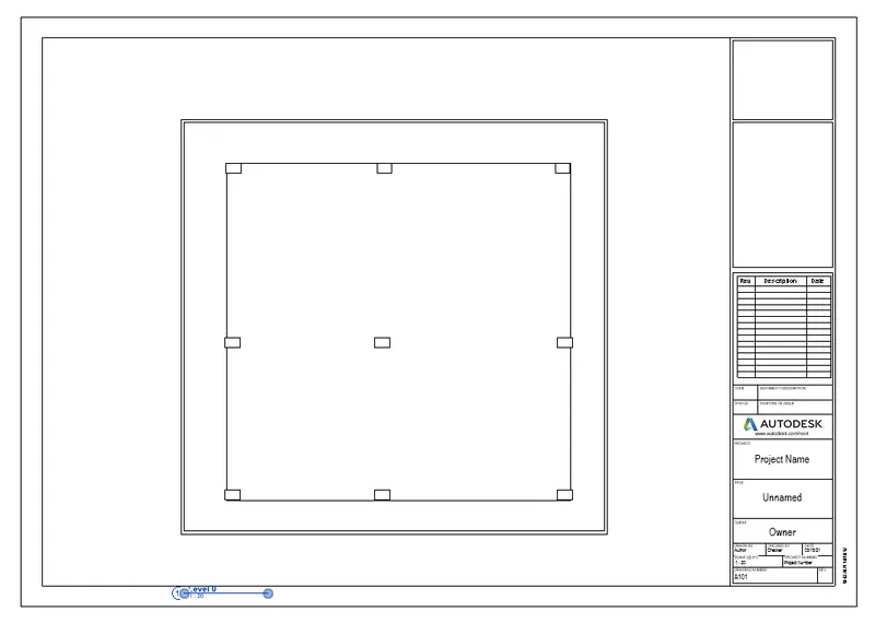
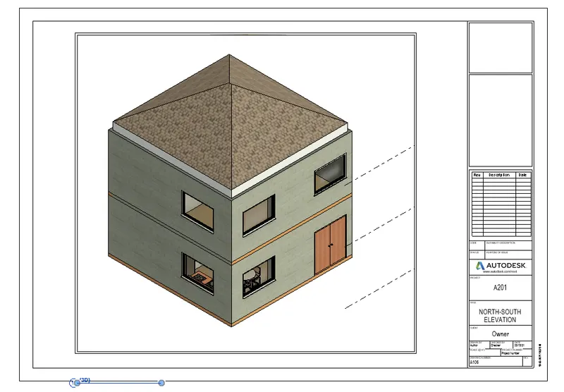
A-201- North-South Elevations
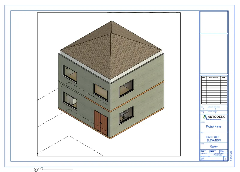
h. A-202- East-West Elevations
SECTION VIEWS-
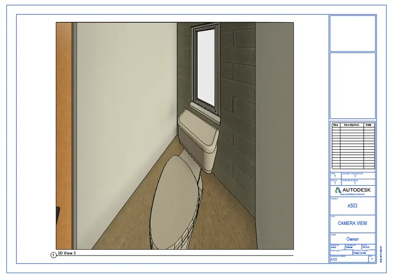
- Creating a camera view in each room.
- Open a plan, section, or elevation view.
- Click View tabCreate panel3D View drop-downCamera.
- Click in the drawing area to place the camera.
- Drag the cursor to the desired target and click to place it.
- Revit creates a perspective 3D view and assigns a name to the view: 3D View1, 3D View2, and so on. To rename the view, in the Project Browser right-click it, and select Rename.
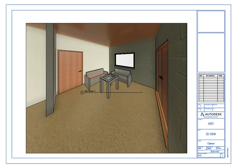
LIVING ROOM CAMERA VIEW-
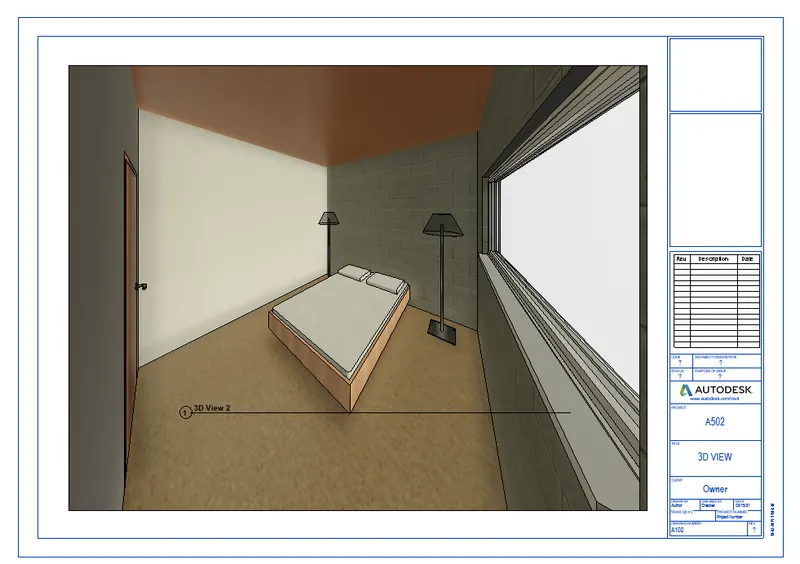
BED ROOM CAMERA VIEW
WASH ROOM CAMERA VIEW-
KITCHEN CAMERA VIEW-
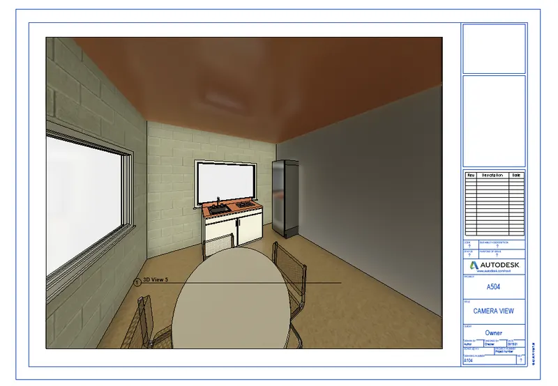
KITCHEN AND LIVING COMBINED CAMERA VIEW-