Creating Architectural and Structural model with 3D rendering using REVIT
PROJECT-2
1. Select the type of structure you want to build from one of the three below:
a. Multi-Unit Residential Apartment
b. Office Buildings
c. School
- The type of Structure Selected is Multi-Unit Residential Apartment.
2.Assume reasonable assumptions for geographic and location details for your project modeling. Based on assumptions and type of structure selected identify the modeling requirements from NBC.
Building is located in Malwan (Maharashtra).
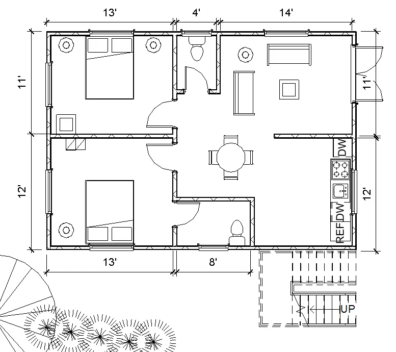
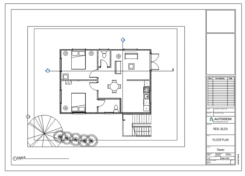
Sizes of rooms are as follows-
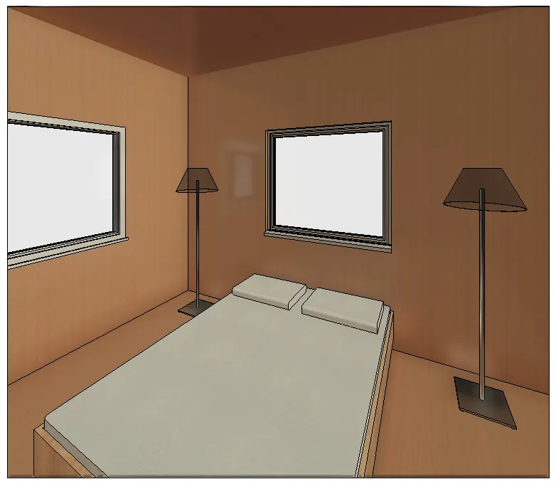
- Bed room 1= 13’ X 10’7’’
- Bed room 2= 13’ X 11’6’’
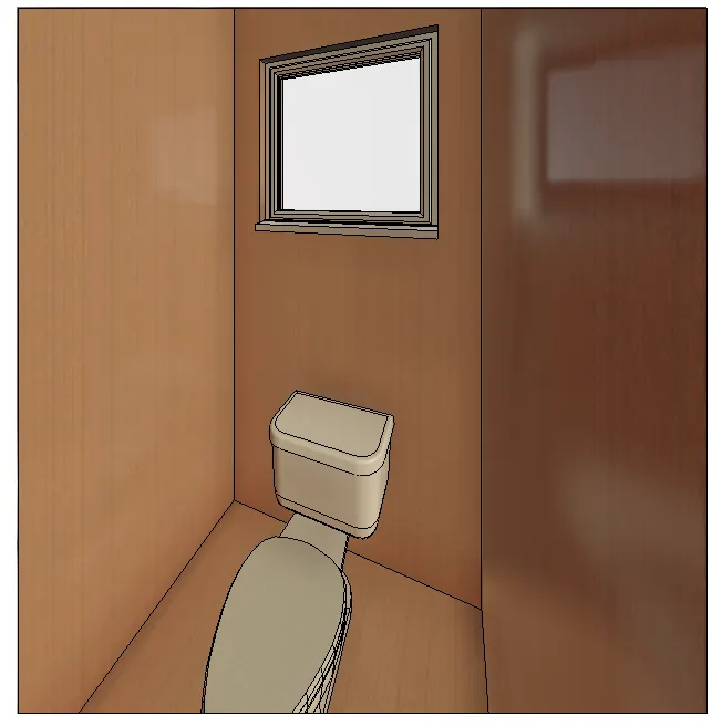
- Toilet 1= 9’ X 5’
- Toilet 2= 4’6’’ X 6’
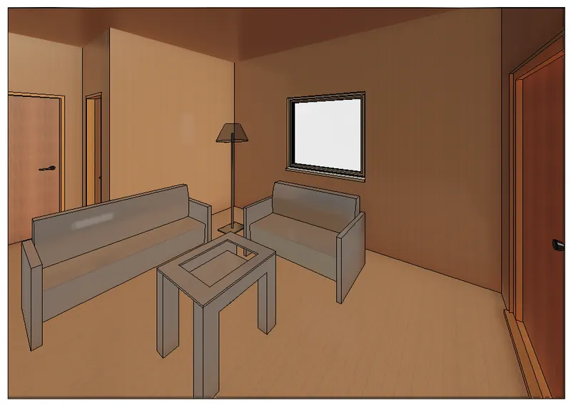
- Living room= 13’5’’ X 10’7’’
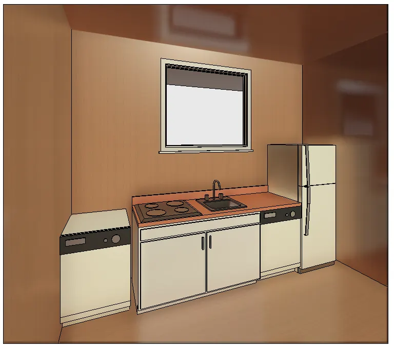
- Kitchen = 8’3’’ X 11’6’’
Building lies in high rainfall area so sloping roof is provided at the top of the building.
Total height of building is 33’.
The road in front of building is 40’.
The room sizes are more than the minimum size of room requirements from the NBC (National Building Code).
3. Using the structural model, include the following components based on the type of structure selected.
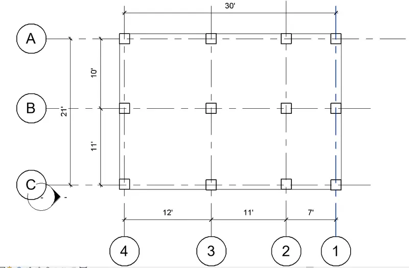
DRAWING GRIDS-
- Navigate to Architecture > Grid or Structure > Grid. Now click once at the start and again at the end of the grid you wish to set up. This should snap to a vertical. Set up however many you need, at approximate spacings this way. Revit labels them 1, 2, 3... Now draw a horizontal grid line. Double click the number and enter the letter "A" instead and hit Enter. Now when you create further horizontal grids they will be labelled A,B,C... Now select each and modify the spacing between them.
DRAWING COLUMNS-
- Click Architecture tab Build panel Column drop-down (Column: Architectural).
- On the Options Bar, specify the following:
- Rotate after placement. Select this option to rotate the column immediately after placing it.
- (3D views only) Select a level for the column's base. For plan views, the view's level is the base level for the column.
- This setting draws the column upward from its base. To draw the column downward from its base, select Depth.
- Level/Unconnected. Select a level for the top of the column, or select Unconnected and specify the column height.
- Room Bounding. Select this option to designate the column as room-bounding before you place it.
- Click in the drawing area to place the column.
- If you need to move the column, select it and drag it to a new position.
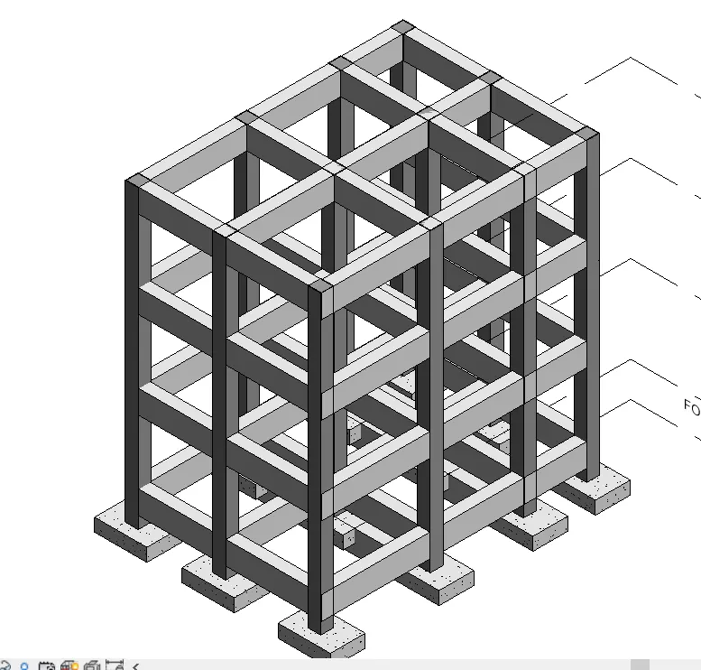
DRAWING BEAM-
- Click Structure tab Structure panel (Beam).
- On the Options Bar:
- Specify a Placement Plane if a work plane other than the current level is required.
- Specify a Structural Usage for the beam.
- Select 3D snapping to snap to other structural elements in any view. You can sketch beams outside of the current work plane. For example, when 3D snapping is enabled, roof beams will snap to the tops of columns, regardless of elevation.
- Select Chain to continuously place beams in succession. The second click in placing a beam will be the start of the next beam. Press Esc to complete chain placing beams.
- Sketch the beam by clicking the start point and endpoint in the drawing area.
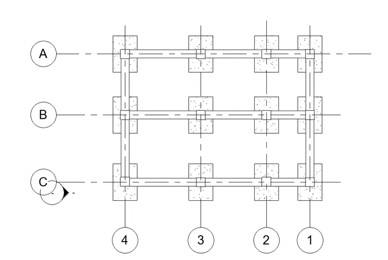
DRAWING FOOTING-
- Click Structure tab Foundation panel Isolated.
- On the Properties palette, select an isolated foundation type from the Type Selector.
- To place a single footing click in the drawing area in either a plan or 3D view.
- To place multiple instances of the footing at the intersection of grids in a plan view, click Modify | Place Isolated Foundation Multiple panel At Grids. Select the grids and click Finish.
- To place multiple instances of the footing beneath specific columns, click Modify | Place Isolated Foundation Multiple panel At Columns. Select the columns and click
- The Bottom Elevation of structural foundations (footings) is reported in a read-only instance parameter called Elevation at Bottom. You can then display this value in a view by tagging the foundation with the Structural Foundation Tag with Elevation tag. It is available from the family library, under Structural/Annotations
DRAWING FLOOR-
- Click Architecture tab Build panel Floor drop-down (Floor: Architectural).
- Draw the floor boundaries, using one of the following methods:
- Pick walls: By default, Pick Walls is active. If it is not active, click Modify | Create Floor Boundary Tab Draw panel (Pick Walls). Select walls in the drawing area to use as floor boundaries.
- Sketch boundaries: To sketch the profile of the floor, click Modify | Create Floor Boundary tab Draw panel, and select a sketching tool. See Sketching.
- The floor boundary must be a closed loop (profile). To create an opening in the floor, you can sketch another closed loop where you want the opening to appear.
- On the Options Bar, for Offset, specify an offset for the floor edges.
- Click Finish Edit Mode
DRAWING GRIDS AND COLUMNS-
DRAWING BEAMS AND FOOTINGS (ISOLATED FOOTINGS)-
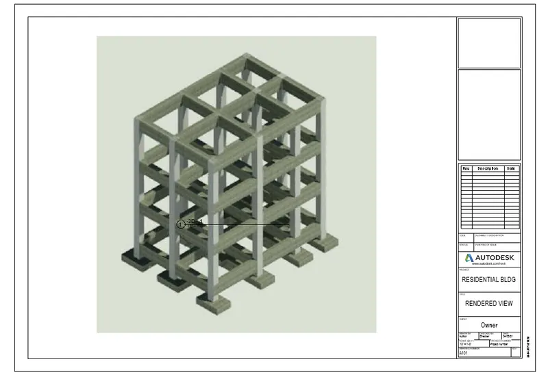
BEAM COLUMN FRAME-
DRAWING FLOORS-
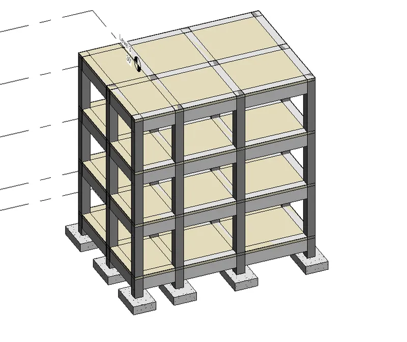
LEVELS-
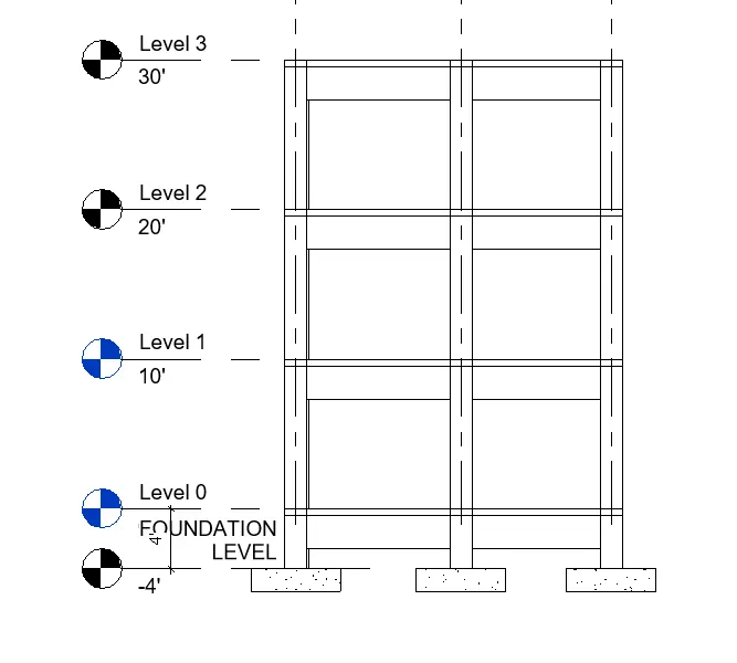
4. Using the architectural model, include the components based on the type of structure selected.
ARCHITECTURE PLANS-
- Create walls in the architectural tab.
- Select suitable type of wall.
- Select wall finish for decoration of walls.
- Place windows and doors in the architectural tab and place it to the desired locations.
- Add furniture to the building using the load family from insert tab.
- Load the suitable families and add the components and units
PLAN OF MULTI UNIT RESIDENTIAL BUILDING WITH VARIOUS COMPONENTS-
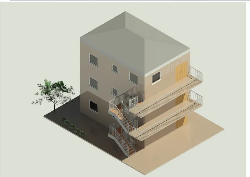
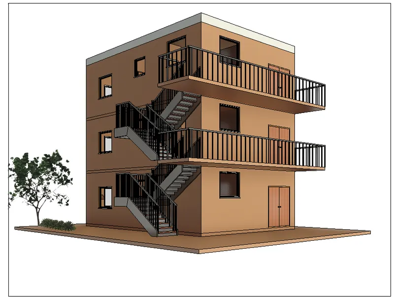
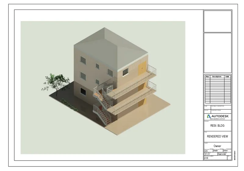
RENDERED VIEW OF BUILDING-
RENDERED VIEW-
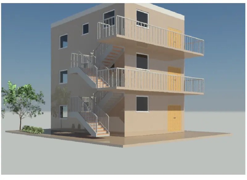
DIFFERENT 3D VIEWS OF BUILDING-
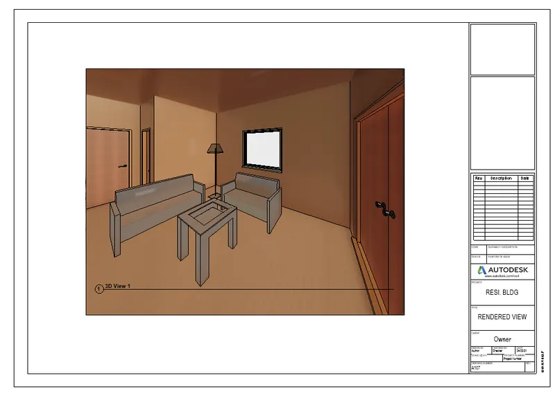
LIVING ROOM-
BED-ROOM -
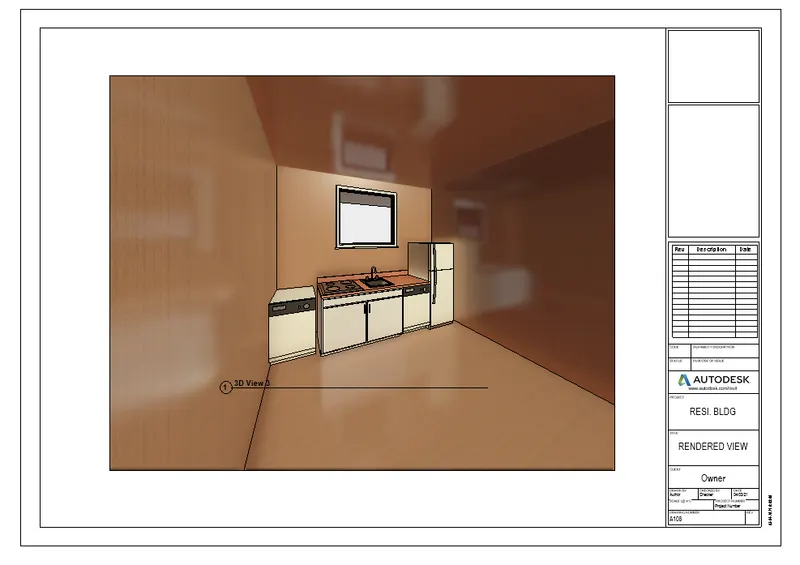
KITCHEN-
TOILETS-
5. Provide a set of drawings in an architectural and structural model to list the following details with categories and appropriate sheet templates included
a. Floor Plans with Annotations.
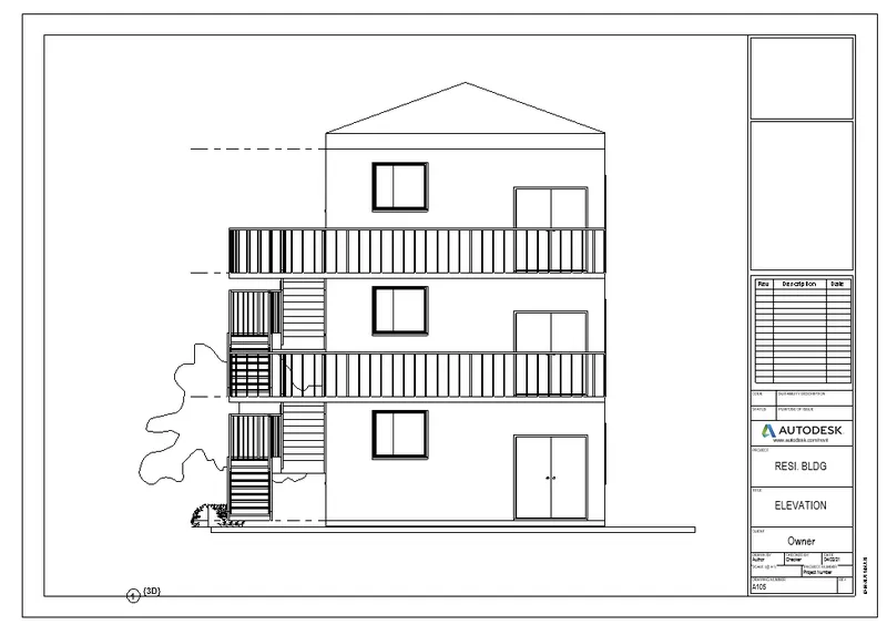
b. Elevations.
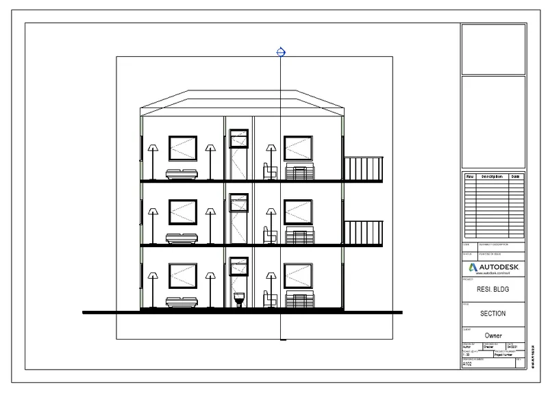
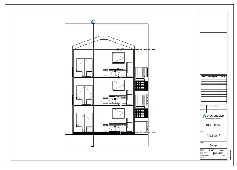
c. Sections.
CREATEING SHEET TEMPLATE-
- Go to the view tab.
- Select sheet.
- A popup window will be appearing on the screen.
- Select the sheet template or customize according to the user needs.
FLOOR PLAN SHEET-
ELEVATION SHEET-
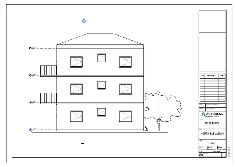
SECTION SHEET-
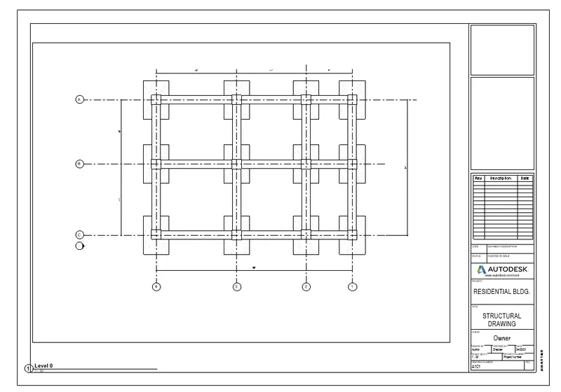
STRUCTURAL DRAWINGS-
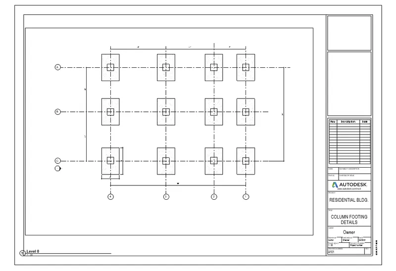
COLUMN FOOTING DETAILS-
6. Using the Rendering settings, Render images of the 3D model produced and include the rendered images to the drawing sheets
a. Rendering from interior rooms.
b. Rendering from out showing topographic features.
c. Rendering through structural framing.
RENDERING IN REVIT-
Render the view to create a photorealistic image of the 3D model.
Before starting the render process, see Best Practices: Rendering for info mation about how you can improve performance.
After preparing the 3D view and using the Rendering dialog to select desired settings, click Render to render the image.
Revit begins the rendering process, rendering the entire image progressively. Revit displays a progress dialog, which shows information about the rendering process.
When the rendering process is complete, Revit displays the rendered image in the drawing area.
You can then do the following:
- Change render settings, and render the image again.
- Adjust exposure settings, and render the image again.
- Save the rendered image as a project view.
- Export the rendered image to a file.
- Display the building model in the drawing area.
- In the Rendering dialog, click Show the model. To display the rendered image again, click Show the rendering
7. Print the set of drawing sheets created and submit the drawings from the architecture and structure mode
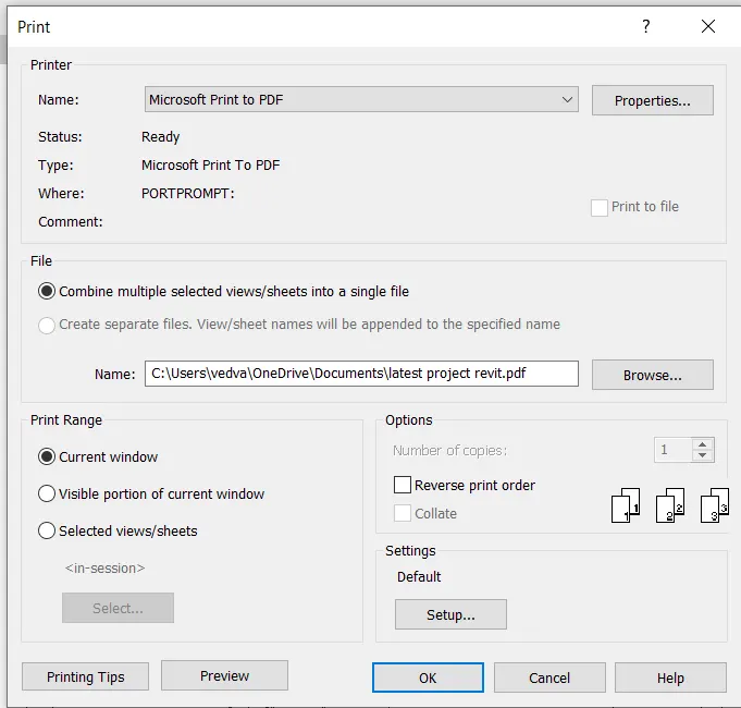
PRINTING OF SHEETS IN REVIT-
- Click File tab (Print).
- In the Print dialog, for Name, select a printer.
- Click Properties to configure the printer.
- Select Print to File. You can save the print job as a PRN or PLT file.
- To print to PDF, do not use this option. Instead, select a PDF print driver in the Name field.
- Under Print Range, specify whether you are printing the current window, a visible portion of current window, or selected views/sheets. If you are printing selected views and sheets, click Select, select the views and sheets to print, and click OK.
- When you are printing selected views and sheets to a file, Revit creates one file per view or sheet. If you want to create a single file that contains all selected views and sheets, print to PDF.
- Under Options, specify the number of copies to print and whether to print a view/sheet set in reverse order. You can select Reverse Print Order for a multiple-page print job so that the last page is printed first.
- To print a complete copy of the project before the first page of the next copy is printed, select Collate. To print all copies of the first page and then print all copies of each subsequent page, clear Collate.
- To change print settings, under Settings, click Setup.
- When you are ready to print, click OK.
SET OF DRAWINGS ARE PRINTED AND SUBMITTED.