Creating various 3D Models like Furniture, Footing, Girder, Column drop with panel and Gable Wall in AutoCad
CHALLENGE 11-
INTRODUCTION- COMMANDS USEDFOR DRAWING THE 3D OBJECTS ARE AS FOLLOWS.
- Extrude- Location: Draw > Modeling > Extrude
This AutoCAD 3D Extrude command allows the user to create a 3D object by extruding a 2D face along a line or path.
- Sweep- Location: Draw > Modeling > Sweep
This command helps the user to extrude the 2D objects without the 2D face being orthogonal to the beginning of the path.
- Union- Location: Modify > Solids Editing > Union
This AutoCAD 3D command allows the user to combine two objects converting into one single object.
- Subtract- Location: Modify > Solids Editing > Subtract
This command is opposite to the union command; this command works when there is a common area in both the objects. Then this command subtracts the object A from the object B.
- Intersect- Location: Modify > Solid Editing > Intersect
With this AutoCAD 3D command the user is left with the area that is common to both the objects.
- Revolve- Location: Draw > Modeling > Revolve
This AutoCAD 3D command creates a 3D solid by revolving a 2D object around an axis.
PROBLEM-1
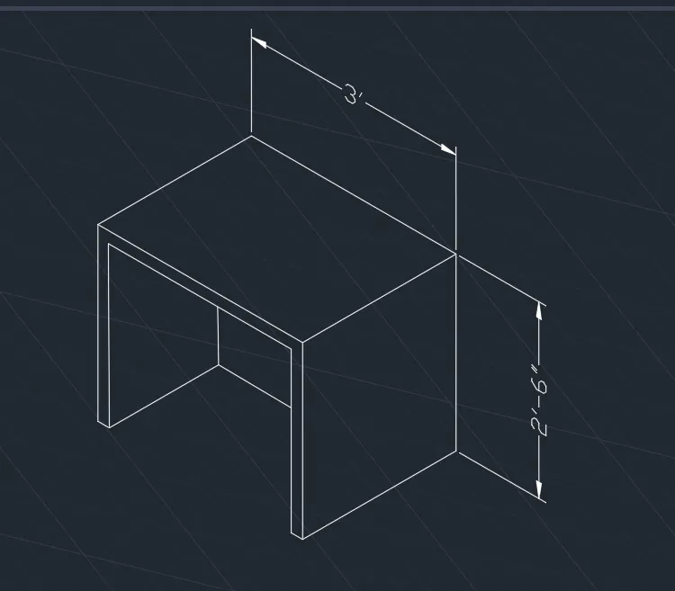
AIM- TO DRAW A 3D FURNITURE ELEMENT.
STEPS.
- Open Auto Cad.
- In the right left corner click on the settings icon that is the icon of workspace.
- Select 3d modelling.
- Enter UN (Units ) command in the command box and change the type as engineering and select precision as 0’-0’’.
- Now enter Dim style in command box and modify the settings and select primary units as engineering and give precision as 0’-0’’.
- Line command is used to draw the 3D object.
- Command line draw the line 2’6’’ in Z direction.
- Line of 3’ in the the Y direction.
- Line 2’6’’ in the negative Z direction.
- Offset of 2’’ as the thickness of the 3D object.
- Assume the width of the object as 2’3’’.
- Move the UCS usind the command 3D face and place in the desired manner to very side to give the dimension using the Dim linear command.
- Use face command and select the particular face and then give the dimensions using the dim linear command.
PROBLEM-2
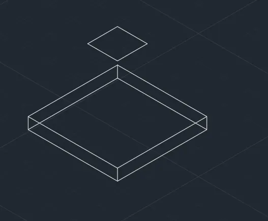
AIM- TO CREATE A 3D MODEL OF ISOLATED FOOTING.
STEPS-
- Open Auto Cad.
- In the right left corner click on the settings icon that is the icon of workspace.
- Select 3d modelling.
- Enter UN (Units ) command in the command box and change the type as engineering and select precision as 0’-0’’.
- Now enter Dim style in command box and modify the settings and select primary units as engineering and give precision as 0’-0’’.
- Draw a rectangle of 1’x 1’ in the 3d view.
- Give an offset of 1’ to the rectangle in the outside of the rectangle.
- Extrude the bigger rectangle to the eight of 6’’.
- Move the inner rectangle at the height of 2’6’’.
- Join all the corner points.
- Use the command 3d orbit to move the object in the degred mannerand join all the corner points.
PROBLEM-3
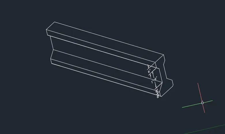
AIM- TO CREATE A 3D VIEW OF ASTO TYPE GIRDER.
STEPS-
- Open Auto Cad.
- In the right left corner click on the settings icon that is the icon of workspace.
- Select 3d modelling.
- Enter UN (Units ) command in the command box and change the type as engineering and select precision as 0’-0’’.
- Now enter Dim style in command box and modify the settings and select primary units as engineering and give precision as 0’-0’’.
- Create the front view of the ashto type girder as shown in the 3d view using the line command.
- Extrude the object in the 3d view.
- Use the 3D orbit command and move the object as desired

PROBLEM-4
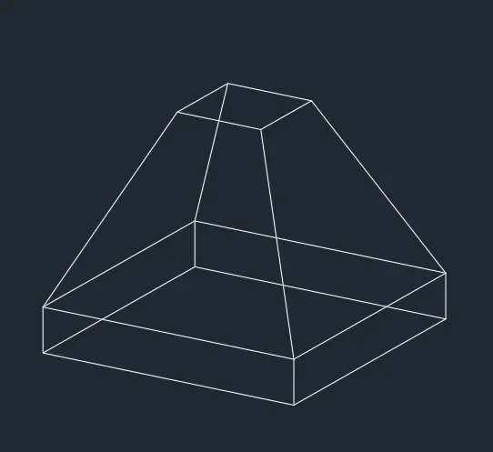
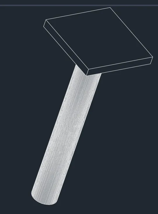
AIM- TO CREATE A 3D MODEL OF DROP COLUMN.
STEPS-
- Open Auto Cad.
- In the right left corner click on the settings icon that is the icon of workspace.
- Select 3d modelling.
- Enter UN (Units ) command in the command box and change the type as engineering and select precision as 0’-0’’.
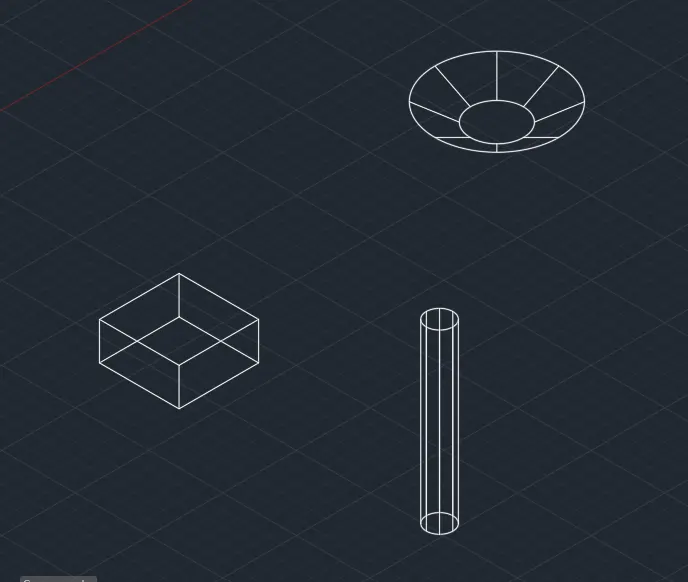
- Draw a circle in the 3D mode of 1’6’’.
- Extrude the circle by using the extrude command in the ribbon 10’ long.
- Use the command cone and draw the cone of 3’6’’ and bottom side of 1’ 6’’ with the height of 1’.
- Again, draw the rectangle of 4’ 6’’ and extrude it with thickness of 6’’.
- By using the command 3D move the objects and place it on one another as desired in the 3D figure.
- Use the 3D orbit command to align the figure.
- Use dim linear command to give the dimension.
PROBLEM 5-
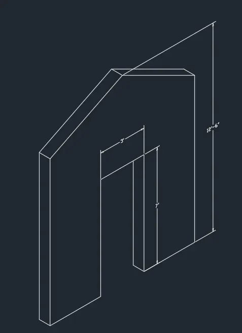
AIM- TO CREATE A 3D MODEL OF THE GABLE WALL.
STEPS.
- Open Auto Cad.
- In the right left corner click on the settings icon that is the icon of workspace.
- Select 3d modelling.
- Enter UN (Units ) command in the command box and change the type as engineering and select precision as 0’-0’’.
- Now enter Dim style in command box and modify the settings and select primary units as engineering and give precision as 0’-0’’.
- Using line command to draw the wall.
- Draw a line of 10’ in the X direction.
- Specify the center of the line of 1’
- Draw a line of 1’-5’’ in both the direction with the height of 7’ to draw the door of the wall.
- The thickness of the wall is considered as 9’’.
- Draw the top of the wall on the distance of 12’-6’’ from the bottom. Offset 9’’ to draw the roof of the wall.
- Use dim linear command to give the dimensions.
- Move the UCS using the command 3 point from the ribbon and give the dimensions.