Modelling of 25 storey building with the specified properties using ETABS
CHALLENGE-6
AIM- MODELLING A 25 STOREY BUILDING IN ETABS.
DATA-
- Beam Size= (300 X 400) mm.
- Column Size= (800 X 800) mm.
- Slab Thickness= 150 mm.
- Height of storey= 3m.
- Height of plinth= 1.5m.
STEPS-
STEP-1
- Open ETABS 2019.
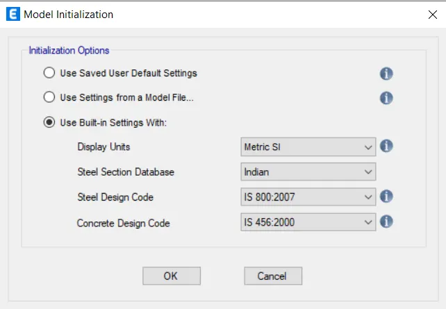
- Go to file menu and select new model, a pop up window of model initialization will be opening.
- Select use built in settings.
- Select display units as Metric SI, Steel section data base as Indian, Steel design code as IS 800:2007, concrete design code as IS 456:2000.
- Select OK.
STEP-2
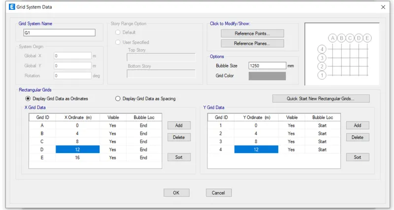
- A new window of new model quick templates will be appearing.
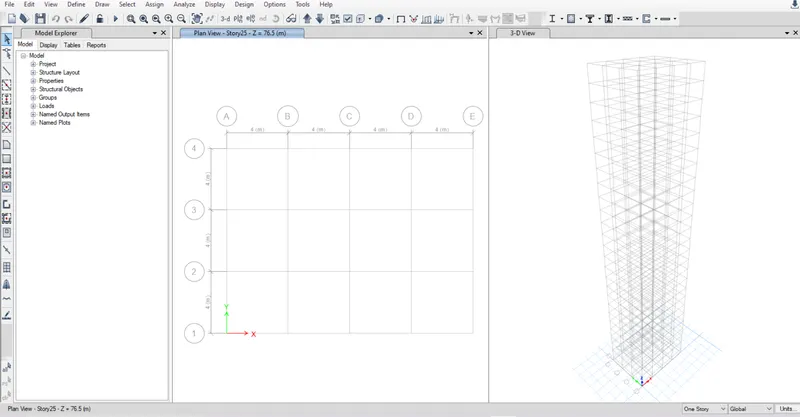
- Select the grids and customise grids.
- Set X grid data at spacing of 4m, and number of grids is 5.
- Set Y grid data at spacing of 4m, and number of grids is 4.
- Click OK
STEP-3
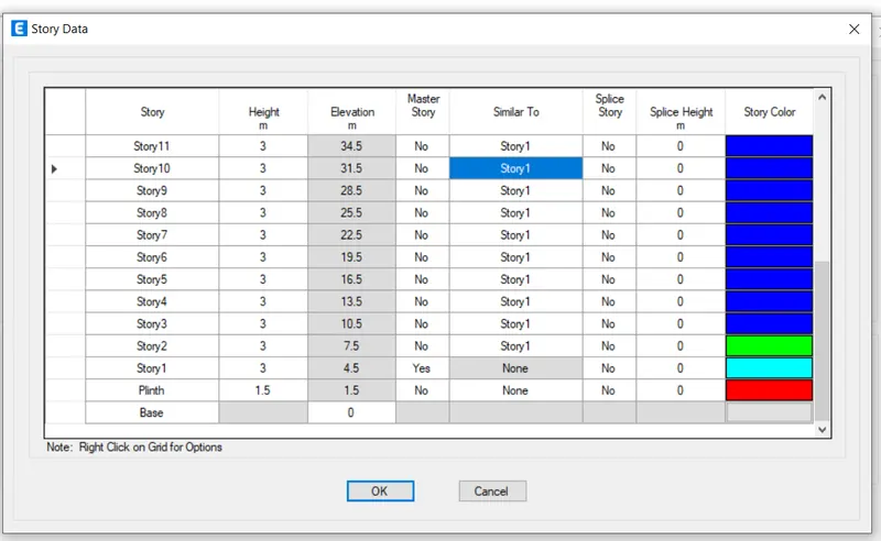
- Now select the option custom story data and select edit storey data.
- Select plinth height as 1.5m, and height of storey as 3m.
- Add storey and make total number of story as 25.
- Keep master storey 1 as yes.
- Click OK.
STEP-4
- Defining the properties of elements.
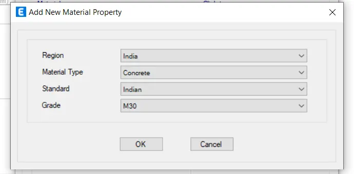
- Go to define and select material properties.
- Select grade of concrete as M30.
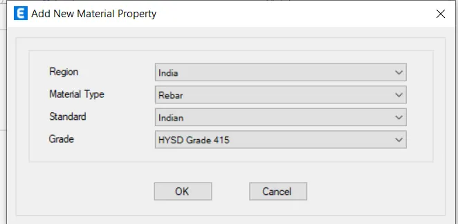
- Select steel as HYSD 500and HYSD 415 steel.
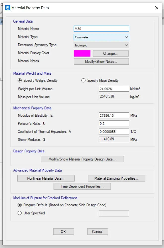
PROPERTY OF CONCRETE.
CONCRETE MATERIAL PROPERTY DATA-
PROPERTY OF STEEL-
STEP-5
- Defining beam column properties.
- Go to define tab, section properties and frame sections.
FRAME PROPERTY TAB.
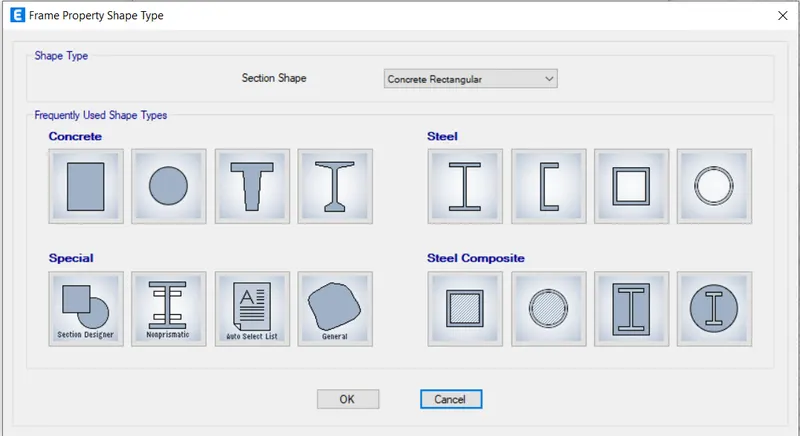
BEAM DETAILS-
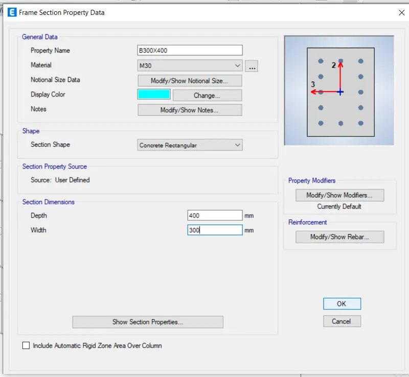
BEAM REINFORCEMENT DETAILS-
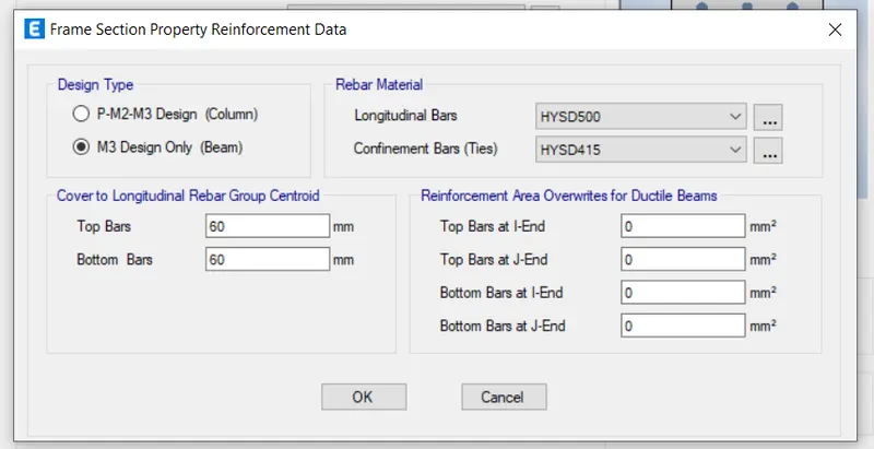
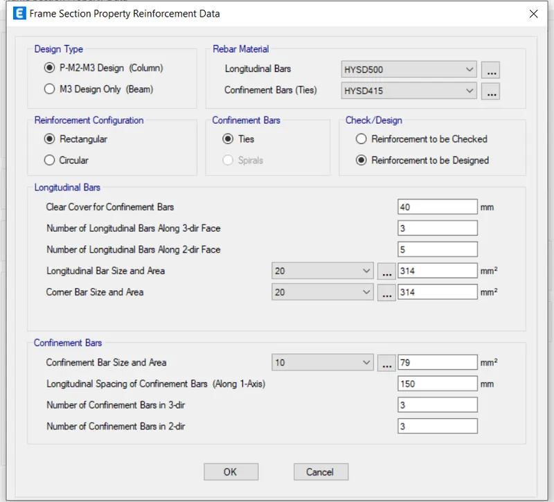
COLUMN PROPERTES-
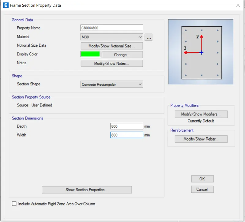
COLUMN REINFORCEMENT DETAILS-
STEP-6
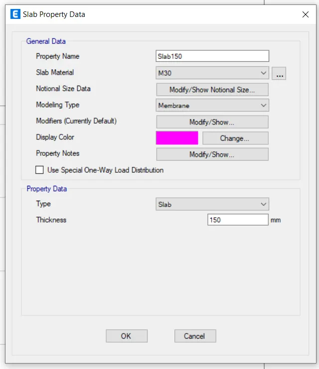
- Defining slab properties.
- Go to define tab, section properties and slab sections.
SLAB PROPERTY DATA
STEP-7
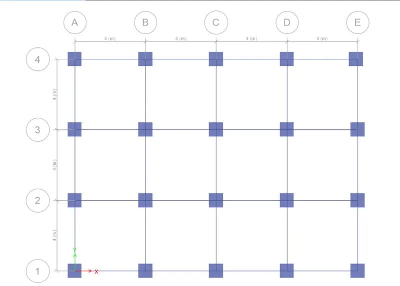
- Drawing of beams and columns.
- In the left side of the draw panel select the option quick draw column.
- Place columns on the grids
- For drawing of beams select the option quick draw beams in the draw panel and place the beams.
DRAWING OF BEAM AND COLUMN.
STEP-8
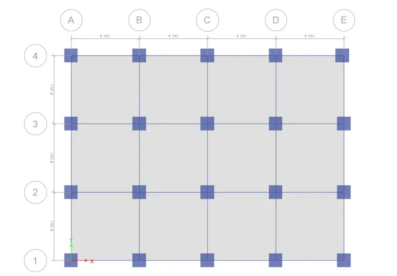
- Drawing of slab.
- In the left side of the draw panel select the option quick draw floor.
- Place slabs between the grids.
STEP-9
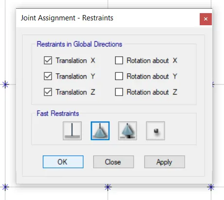
- Change the base connections.
- Go to the base view in the plan.
- Select the base view.
- Select assign tab, joints, restraints and select pinned connection.
JOIN ASSESSMENT DETAIL.
STEP-10
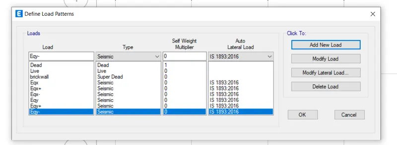
- Assigning loads on the structure.
- Select define, load patterns and enter the load patterns as shown in the image.
DEFINING LOAD PATTERNS
STEP-11
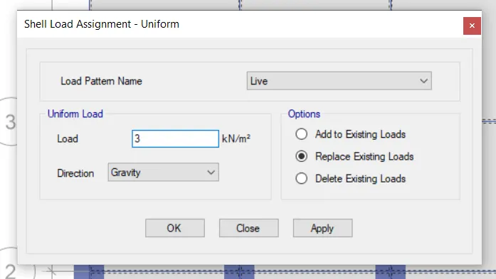
- Assigning live loads.
- Go to assign tab and select shell loads , uniform and assign load of 3KN/M^2.
STEP-12
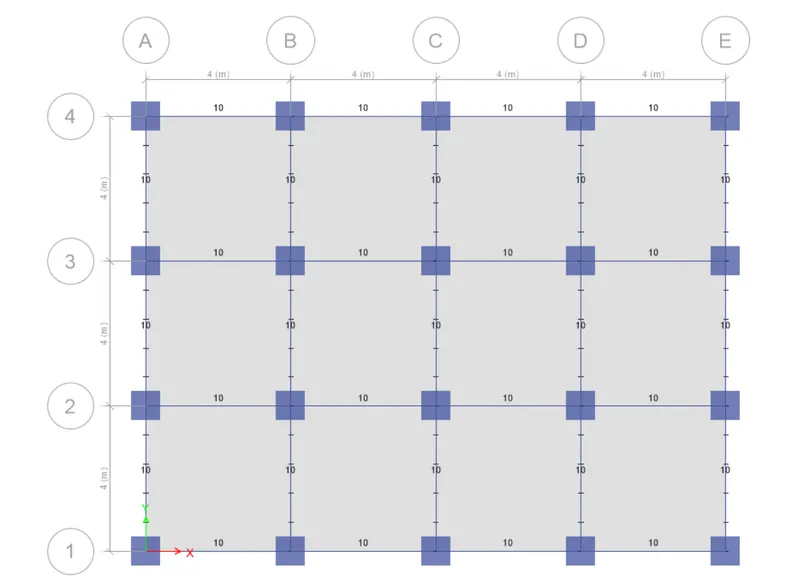
- Assigning load on beam as brick wall load.
- Apply load of 10KN/M.
BRICK WALL LOAD PATTERN TYPE-

BRICK WALL LOAD APPLIED ON BEAMS-
STEP-13
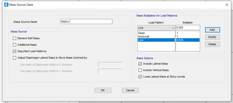
- Assigning mass source to model.
- Go to define tab select mass source and enter the details as shown in the image.
MASS SOURCE DATA-
STEP-14
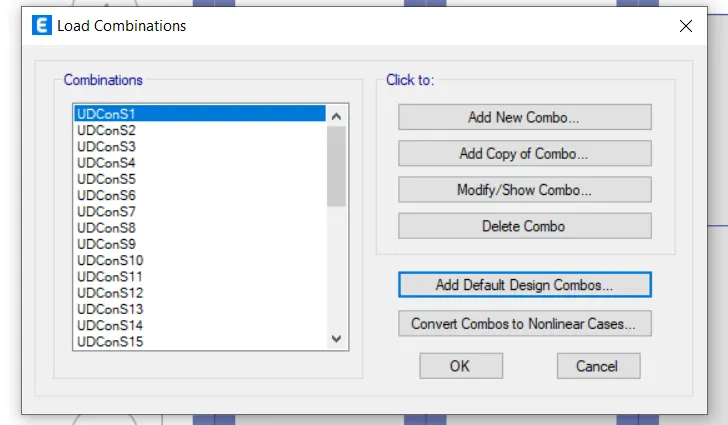
- Generating load combinations.
- Select define tab- load combinations- add default- concrete frame- convert to editable.
LOAD COMBINATION DATA-
STEP-15
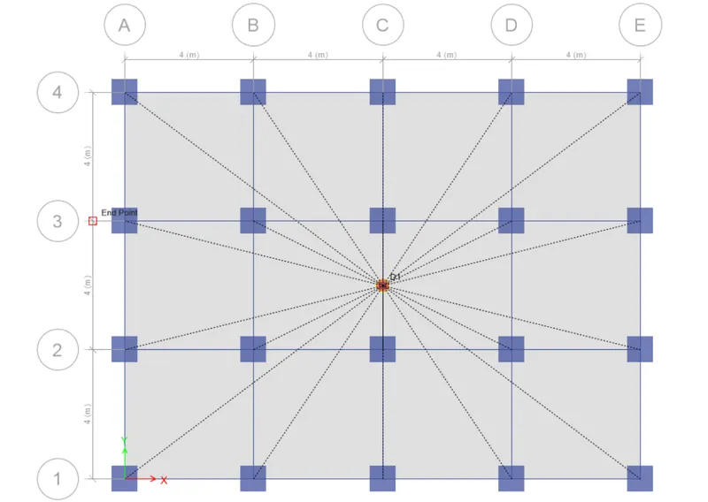
- Assigning diaphragms to the model.
- Go to assign tab select shell, select diaphragms and select D1.
- Apply the diaphragms.
STEP-16
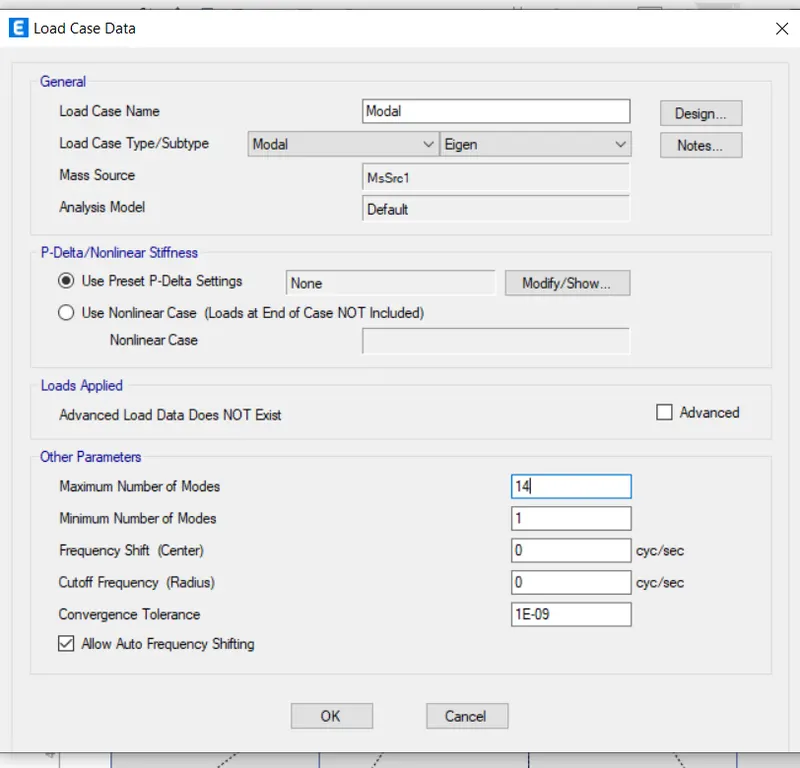
- Creating modal analysis.
- Go to define tab-modal cases- modify.
- Enter the data as shown in the image.
STEP- 17
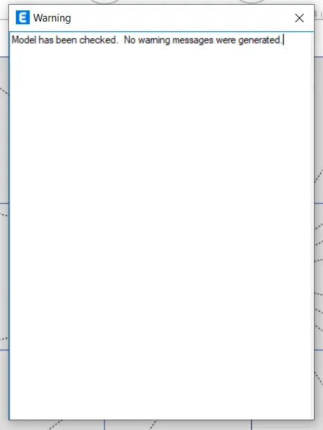
- Checking the model.
- Go to the analyse tab and select option check model.
STEP-18
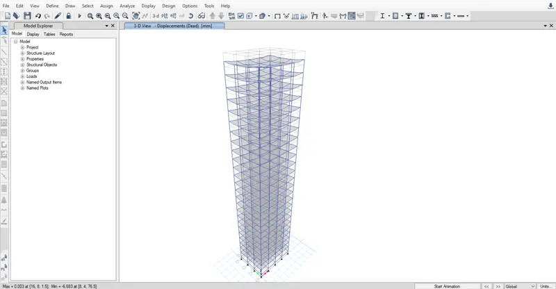
- Running the analysis.
AFTER RUNNING THE ANALYSIS-
STEP-19
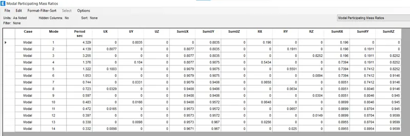
- Modal results.
- Select display- show tables- structure output- modal information- modal participation mass ratios.
- A table will be appearing on the screen.