Photo Realistic Rendering of American Chopper
INTRODUCTION
Through this project, we will learn how to design an American Chopper assembly using SOLIDWORKS. First, we will learn how to use the software, then we will draw parts using blueprint sketches, where we can learn the dimensions of the parts, Once the chopper parts have been designed, we assemble the chopper. We then add decals, lights, and cameras, and render the chopper using SOLIDWORK visualization.
The Components that we learned and designed in a Chopper are:
- Chassis
- Engine with the exhaust system.
- Front-wheel and rear wheel with rims and sprocket calipers.
- Front Fork
- Front and rear fender
- Oil tank
- Chain and transmission belt
- Kickstand and foot pedal
OBJECTIVE
- To learn the basic commands of SOLIDWORK.
- With the help of a blueprint sketch, we design all the parts of the chopper.
- Assembling all the parts in SOLIDWORK.
- Get the knowledge of concepts like decals, light, and camera angle.
- Proper setting of image quality and getting realistic view with the help of photo view 360.
- Rendering of American chopper has been done with help of Solidworks visualization software.
DESIGN APPROACH:
As part of the design process, there are two types of approaches. 1. Bottom-up approach and 2. Top-down approach. Here, we have used the bottom-up approach, and we get a clear picture by defining these terms.
- Bottom-up Approach: In this design approach, the most primary operations are specified first, then they are combined later to make larger progressive units.
- Top-Down Approach: This approach is an Assembly-centric modeling method in which an assembly design is done at the highest level possible, and individual parts and subassemblies are defined within the context of the overall assembly.
In order to design different parts, we used the following features and Properties:
- Extrude boss
- Fillet
- Revolve boss feature
- Extrude cut
- Shell
- Linear pattern
- Mirror
- Reference geometry
- Projected curve
- Knit
- Mate
Extruded Boss:
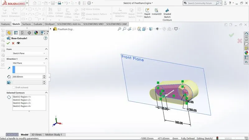
Extrude boss is the most basic feature of SOLIDWORKS. It requires a complete sketch to convert a 2D sketch into a solid body. After you exit a fully defined sketch you see the boss extrude option and a property manager window opens. Using the property manager, we can see from where the feature begins and ends that we need to add dimensions to it. It creates a completely solid body of any shape with closed entities. In this feature, we can add dimensions to both the direction (direction 1 and direction 2) and the size.
Fillet:
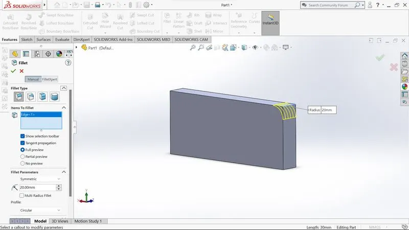
When a solid part is drawn, it will be having some sharp edges to give roundness to these edges we add fillets. It will make the sharp edges or corners a round shape having different sizes and radius. The material can be added or can be removed according to the conditions whether the edges are internal or external. fillets are used in solid bodies to hide corners and edges also giving a nice appearance to the part. Various types of fillets are used depending upon the part.
Revolve boss feature:
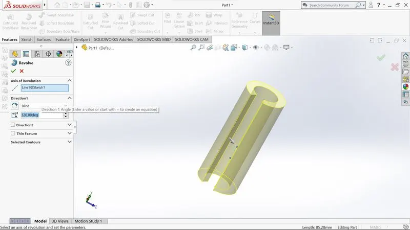
This feature works by selecting the axis of a sketch adding a round material by revolving around the selected axis. We can select an edge of a sketch if there is no axis given
Extrude cut:
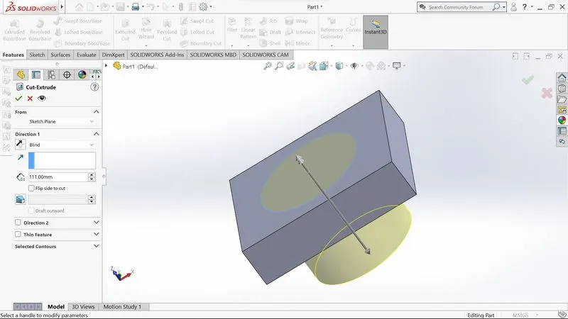
This feature allows you to remove unnecessary parts from the geometry or to give the desired shape to a sketch or solid part by drawing the sketch on the solid part and then using this feature to get rid of that part.
Shell:
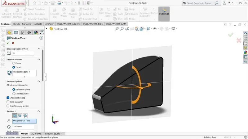
There is a very handy tool in SolidWorks that allows you to see what the inside geometry of a part will look like. In this tool, we add a thickness to the inside geometry and remove the material from the body so that the part appears hollow.
Linear pattern:
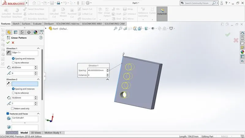
The linear pattern is a feature used to create a single sketch that can be used multiple times. The spacing, angles, and paths of this feature are given so that it can be used to draw or create a pattern This feature is spaced uniformly along one or two linear paths
Mirror:
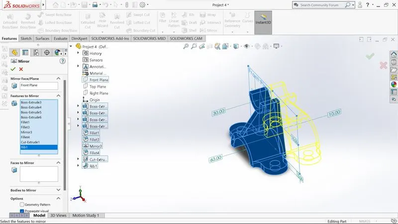
As this feature makes a copy of a solid part, it requires a plane or axis to mirror the part. Select the body to be mirrored, then choose an axis or plane, and then apply the feature. Multibody parts: Apply the feature to one or more multibody parts by selecting geometry patterns and using feature scope to select which bodies the feature should be applied to.
Reference Geometry:
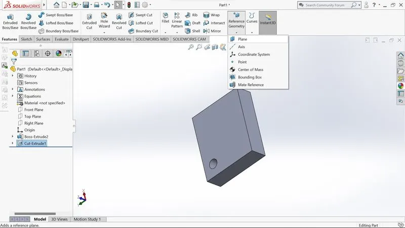
Surfaces and solids are defined by their shape or form. This includes planes, axes, coordinate systems, and points, which can be used in a sketch.
Use of Reference Geometry:
- Axis: If we want to pattern something and the axis is not available, then we can use the reference geometry axis to make it easier to do so.
- Plane: A reference geometry plane can be used to represent a plane when sketching and the sketch needs to be completed using a plane.
Projected Curve:
The curve can be projected by a sketch into a model to create a 3D curve We can create several closed or open contour projected curves from a single sketch Generally, the curve is the intersection of two extruding surfaces The curve which is created can be used as a path for the sketch of the part. Note: It does not create the curve of intersecting curves.
Knit:
Utilization of knit surface tools to combine two or more faces and surfaces into one. It creates a solid body when the knit surfaces form a closed volume or remain as surface bodies.
Mate:
Mates define a geometric relationship between assembly and component. When we add mates, they define the possible direction of linear or rotational motion for a component within its degree of freedom.
This feature includes:
- Coincident mate: Helps in making two planar faces to become coplanar which can be moved along with one another but cannot be separated
- Concentric mate: Helps in making two circular faces be concentric which can only be moved in the common axis
- Tangent: Helps in making a tangent mate between a face and plane
- Angular mate: Helps in making an angular relationship between flat surface and the surface having some angle
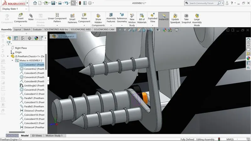
Now let us see the above application of the features in the chopper that we have built which is discussed part by part as shown in the flowchart.
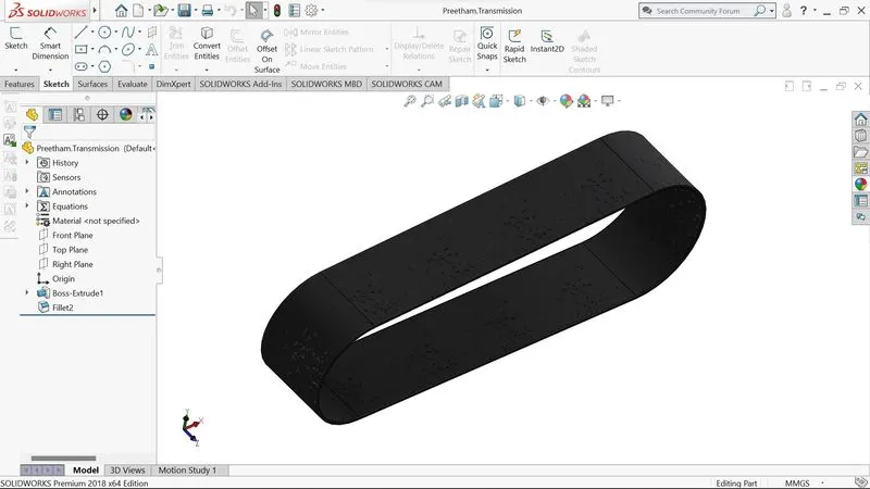
Transmission Belt:
To transmit the power with the help of pulleys, the transmission belt is located at the round surface. Rubber is commonly used for this. It is a solid body in which the transmission belt is filleted and the appearance is that of a matte rubber.
Features used to create:
- Sketch
- Extrude
- Offset
- Fillet
- Appearance
Kick Stand:
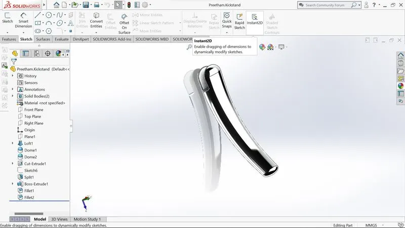
While designing the kickstand, we first drew a sketch based on an additional plane, then used the loft function to construct a portion that was then applied Dome to both sides of the kickstand. Then, using the sketch, a flat surface was made at the bottom to rest the kickstand. For assembling purposes, we employed extruded cut. Following the creation of the two pieces, we applied fillets to the edges and joints of the portion. The kickstand is made of chrome material.
Features used to create:
- Sketch
- Ellipse
- Splines
- Pierce
- Loft
- Cut extrude
- Boss extrude
- Split
Front Fender:
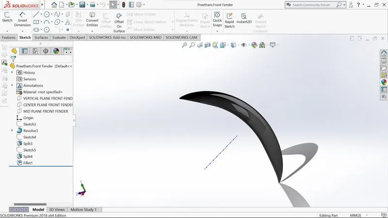
We used an axis to rotate the sketch and produce a half-curved solid body. The material is taken from the split tool to create some sharp edges on both sides of the fender. The fender's edges are filleted.
Features used to create:
- Sketch
- 3-point arc
- Offset
- Extend
- Trim
- Revolve
- Spline
- Fillet
Rear Fender:
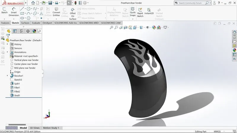
The rear fender is made in the same manner as the front fender. The only difference between the two is size, which is determined by the tyre size. The front and rear fenders are composed of metal with a Dark Black colour.
Features used to create:
- Sketch
- 3-point arc
- Extend
- Trim
- Revolve
- Spline
- Fillet
- Shell
Oil Tank:
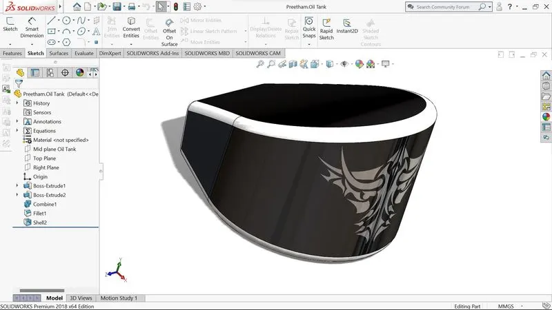
To achieve the construction of the oil tank, the base is drawn on the top plane and extruded above, and another sketch is put on the midplane, which is then extruded and then joined, and finally, a shell function is used to make the part hollow from the inside. To smooth it out, the fillet is applied to the outer edges. The oil tank is painted in a Dark Black, with white paint applied to the filleted edges.
Features used to create:
- Lines
- 3-point arc
- Boss extrude
- Combine
- Fillet
- Shell
Chain Link:
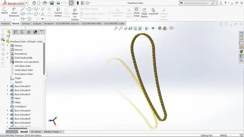
To make the chain, we must first design a sketch with arcs and lines, with the line being tangent to the arc. Then we extrude the sketch of blocks and pins, and the pins and blocks were patterns along the path and the number of pins and blocks was calculated. When the entire front side chain pattern has been completed. The front side of the blocks can then be mirrored to the midplane, resulting in the creation of both sides of the blocks.
This arrangement was created using the sketch as a guide. The linked chain's look is made of a finely finished Brass Material
Features used to create:
- Sketch
- Circles
- 3point arc
- Slot
- Block
- Fillet
- Curve pattern
- Mirror
Pedal:
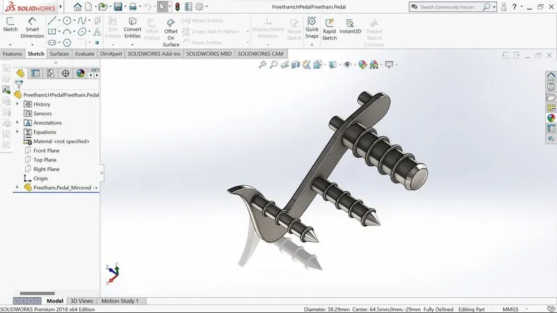
A pedal is a solid, robust body that is used to rest the foot while riding a bicycle. Splines, fillets, dome, chamfer, and a linear pattern are among the features utilised to construct the pedal. The pedal is given a chrome metal appearance.
Features used to create:
- Sketch
- Lines
- Circles
- Fillet
- Revolve
- Dome
- Chamfer
- Linear pattern
Front Wheel:
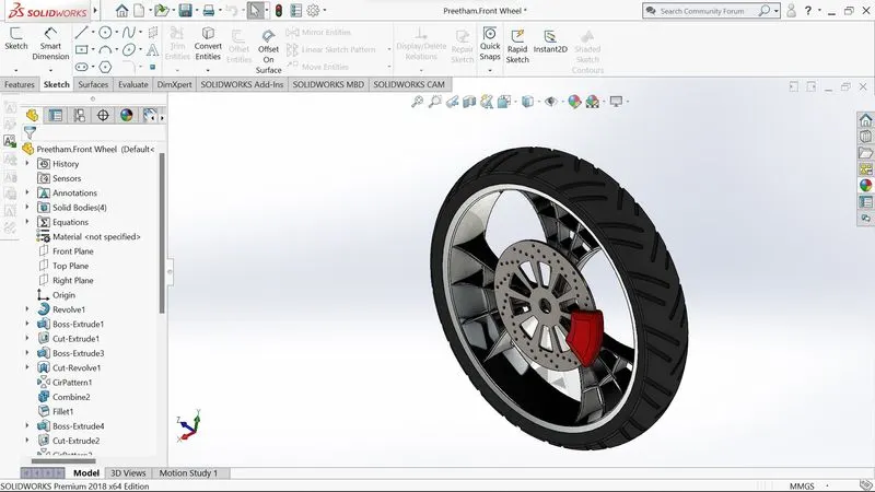
The diameter of the front wheel is bigger than that of the rear wheel. To better handle impact than the back. During braking, the front wheel receives the most force. The revolve boss feature was used to make the rim, and the spider-webbed spokes were made by offsetting splines. The spider-webbed spokes were then applied to the rim in a design. The rotor and calliper were sculpted on the rim. Threads were added to the tyre after it was designed with revolve. The tyre has a matte rubber appearance, while the rotor and spokes are chrome metal, and the calliper is Red in colour.
Features used to create:
- Sketch · Lines · 3-point arc · Sketch fillet · Revolve · Spline
- Extend · Trim · Cut extrude · Offset · Revolve cut
- Circular pattern · Chamfer · Fillet
Rear Wheel:
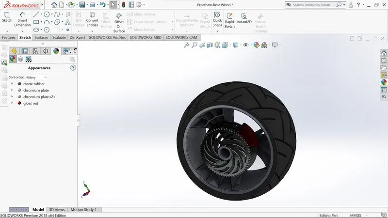
The rear tire's primary function is to accelerate and propel the vehicle forward. Its width is more than that of the front wheel. It ensures the vehicle's stability. The processes were followed in the same way as the front wheel, and the look was likewise the same, with the exception of the addition of a sprocket to link the chain.
Features used to create:
- Sketch · Lines · 3-point arc · Sketch fillet · Revolve · Spline
- Extend · Trim · Extrude cut · Offset · Revolve cut
- Circular pattern · Chamfer · fillet
Front Fork:
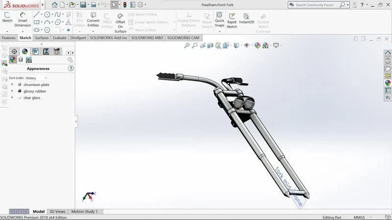
The front fork connects the entire chassis to the front wheel. Triple clamps are commonly used to construct it. It also provides suspension for the entire bike, and the front wheel comprises components such as the front fork, handlebars, headlights, brake, and clutch levers. The half of the front fork has been produced first, and the entire body has been mirrored around the plane. The handles and cables were modelled using projected curves. The front fork's handlebars were provided grips.
Features used to create:
- Sketch · Lines · Revolve · Circle · Fillets · Linear pattern · Spline · Extrude cut · Dome · Curve · Sweep · Plane · Mirror · Combine
Chassis:
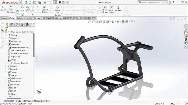
The chassis is the chopper's mainframe. It holds the front fork, pedals, kickstand, oil tank, motor, gas tank, and rear wheel, among other things. It supports all of the bike's components as well as the bike itself. The modelling of the chassis begins with a reference photograph of a chopper. Extruded bosses, splines, and spinning pieces are used to create mirrors and sweep. Finally, a fillet was used to produce the entire portion, giving the chassis a pleasant appearance and rounding the harsh edges. The chassis is given a Dark Black colour.
Features used to create:
- Blueprint sketch · Splines · Curves · Mirror · Boss extrude
- Extrude cut · Chamfer · Dome · Split · Revolve · Combine
Engine:
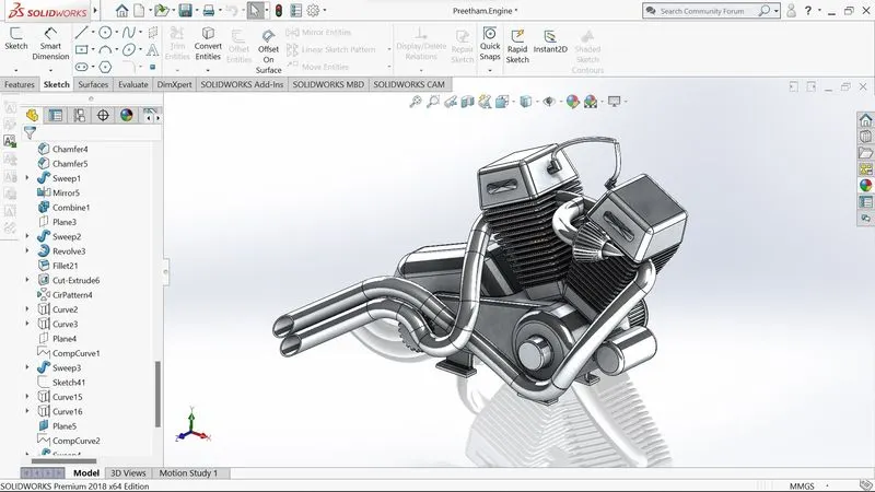
The engine is the most important component of the motorcycle. It's also known as the bike's heart. It supplies the essential power to operate the motorcycle. For modelling purposes, a photo is taken as a reference. The crankshaft, transmission pulleys, and motor are all components of the engine. The cooling fins were situated on the upper half of the crankshaft. Splines were used to create the air filters, while splines, projected curves, and the sweep feature were used to create the exhaust system. The engine's edges have been filled, and it now has a chrome metal appearance.
Features used to create:
- Sketch · Blueprint sketch · Lines · Circles · Boss extrude · Fillet
- Revolve · Dome · Circular pattern · Chamfer · Linear pattern
- Mirror · Cut extrude · Combine · Mirror · Curve
- Composite curve · Split
Gas tank:
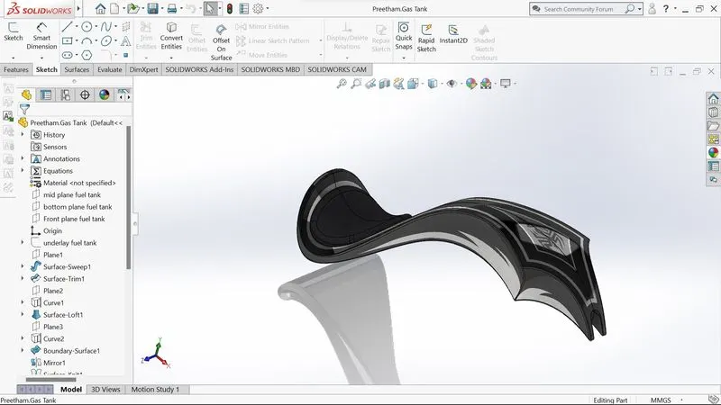
This component is primarily constructed using splines and the sweep feature. The half of the gas tank is first constructed, then mirrored around the plane. The knit feature was used to combine the two independent components into a single piece. The gas tank protects the oil tank and engine by acting as a shield against the engine's heat. The seat was designed to seem like the top of a petrol tank. The fillets were added to the gas tank's edges. The final shell characteristic was to hollow it out from the inside. The Gas tank is given a Dark black colour.
Features used to create:
- Blueprint sketch · Spline · Surface sweep · Surface trim 2
- Surface boundary · Surface loft · Curve · Mirror · Surface knit
- Surface extrudes · Fillet · Extrude cut · Shell
Assembly of chopper:
To assemble the parts, they were all modelled and imported. The Mate function is often used in assembly to locate and relate pieces to one another. The essential component is the chassis, which is inserted first and then fixed. The other components were inserted one by one, utilizing planes for reference and the mating feature to ensure that the part floats with the mainframe once it was fixed. During the assembling process, some parts were changed to make it perfect for the requirements.
Decals:
A decal is a type of "transfer" that consists of a printed picture, image, pattern, or design on a metal body. We've added decals to the chopper's gas tank, rear fender, and oil tank. It gives the chopper a wonderful aesthetic.
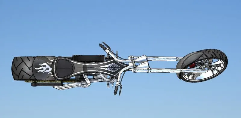
top view
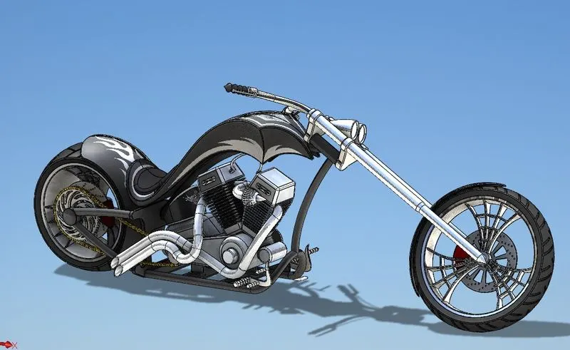
iso view
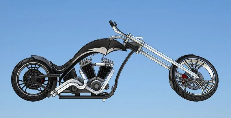
side view
Rendering:
A rendering is an artistic drawing of what a new structure would look like, and it comes from the graphic design field. A rendering is a specific view of a realistic image in Computer-Aided Design (CAD). We obtain a concept of how the chopper would look in the landscape by rendering it. SOLIDWORKS Visualize was used to create this rendering. We may add numerous camera views to the model using PHOTO VIEW 360, and we can configure various angles, directions, and appropriate distances to acquire the optimal camera view. We modify the colour of chopper pieces, backdrop pictures, brightness, rotation, and other helicopter settings during rendering. We can gain more detailed visuals of the scene by increasing the resolution and changing the number of passes.
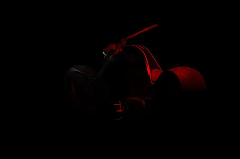
Photo-realistic image rendered using the Spotlight
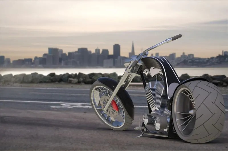
Photo Realistic image 1
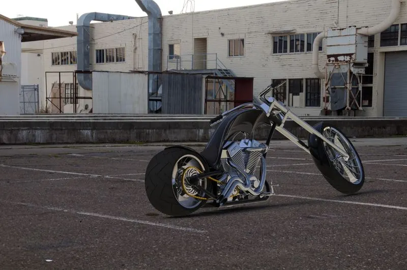
Photo Realistic image 2
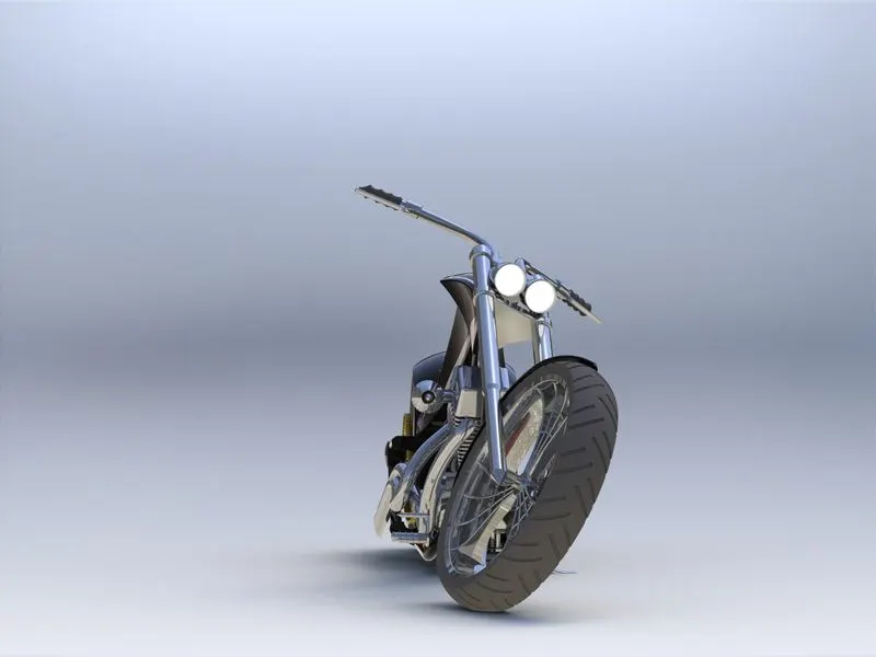
Photo Realistic image front view
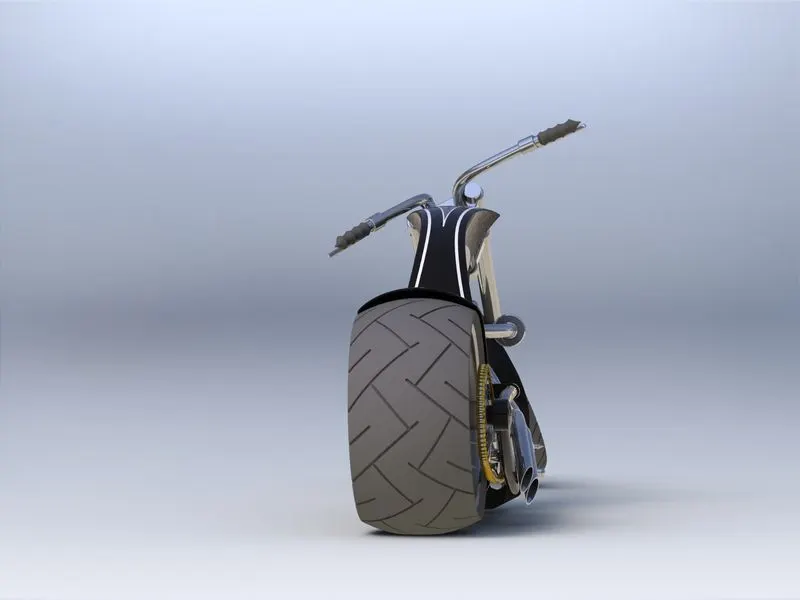
Photo Realistic image back view
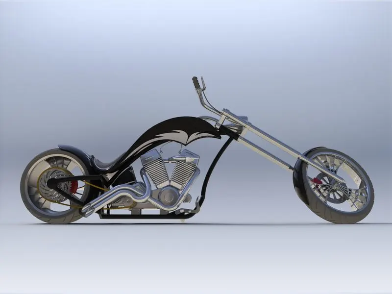
Photo Realistic image side view