Boeing-747 _ Final_Project
INTRODUCTION
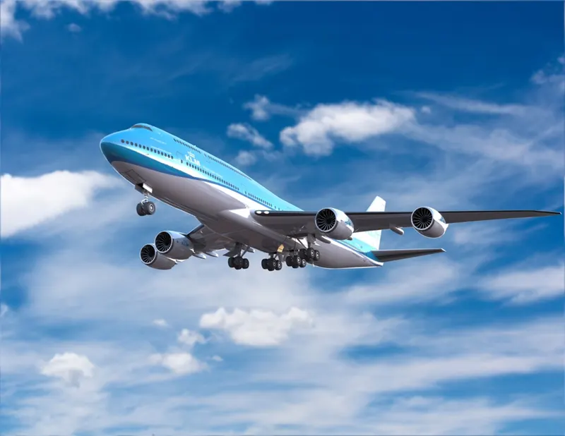
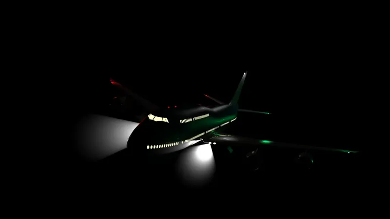
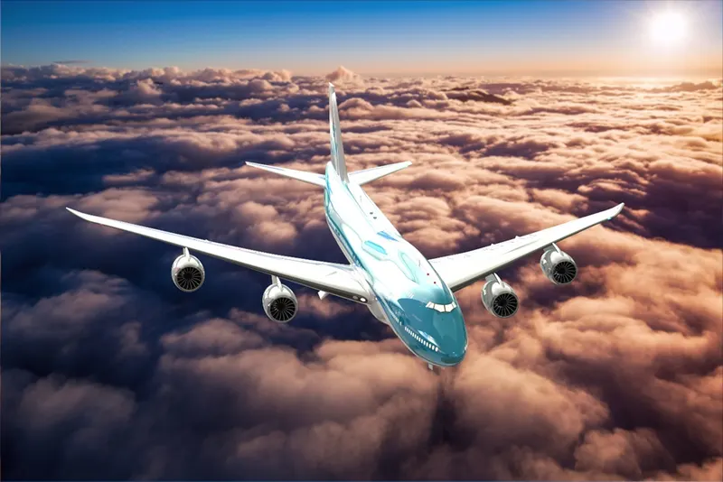
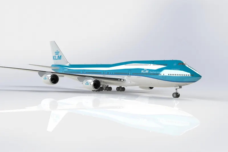
Through this project, we will learn how to design a Boeing 747 assembly using SOLIDWORKS. First, we will learn how to use the software, then we will draw parts using blueprint sketches, where we can learn the dimensions of the parts, Once the Boeing 747 parts have been designed, we assemble the Boeing 747. We then add decals, lights, and cameras, and render the Boeing 747 using SOLIDWORK photo view 360.
The Components that we learned and designed in a Boeing 747 are:
1. Blueprint
2. Fuselage
- Belly fairing
- Nosecone & Pitot tube
- Cockpit windows & Windshield wipers
- Front seat.
- Passenger windows, Doors & Hatches
- Lighting, antennas & Auxiliary Power unit
- Vertical & Horizontal stabilizer, Wings
- Flaps and Ailerons
- Flap track fairing
- Landing gear hatches Open & Closed
- Wheel
- Nose Gear base, Suspension arm & Assembly
- Main Gear base, Suspension arm & Assembly
- Engine
- Livery
OBJECTIVE
- To learn the basic commands of SOLIDWORK.
- With the help of a blueprint sketch, we design all the parts of the Boeing 747.
- Assembling all the parts in SOLIDWORK.
- Get the knowledge of concepts like decals, light, and camera angle.
- Proper setting of image quality and getting realistic view with the help of photo view 360.
DESIGN APPROACH:
As part of the design process, there are two types of approaches. 1. Bottom-up approach and 2. Top-down approach. Here, we have used the bottom-up approach, and we get a clear picture by defining these terms.
- Bottom-up Approach: In this design approach, the most primary operations are specified first, then they are combined later to make larger progressive units.
- Top-Down Approach: This approach is an Assembly-centric modeling method in which an assembly design is done at the highest level possible, and individual parts and subassemblies are defined within the context of the overall assembly.
To design different parts, we used the following features and Properties:
- Extrude boss
- Fillet
- Revolve boss feature
- Extrude cut
- Shell
- Linear pattern
- Mirror
- Reference geometry
- Projected curve
- Knit
- Mate
Extruded Boss:
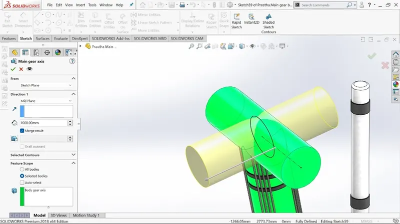
Extrude boss is the most basic feature of SOLIDWORKS. It requires a complete sketch to convert a 2D sketch into a solid body. After you exit a fully defined sketch you see the boss extrude option and a property manager window opens. Using the property manager, we can see from where the feature begins and ends that we need to add dimensions to it. It creates a completely solid body of any shape with closed entities. In this feature, we can add dimensions to both the direction (direction 1 and direction 2) and the size.
Fillet:
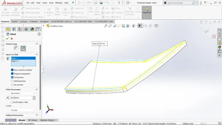
When a solid part is drawn, it will be having some sharp edges to give roundness to these edges we add fillets. It will make the sharp edges or corners a round shape having different sizes and radii. The material can be added or can be removed according to the conditions whether the edges are internal or external. fillets are used in solid bodies to hide corners and edges also giving a nice appearance to the part. Various types of fillets are used depending upon the part.
Revolve boss feature:
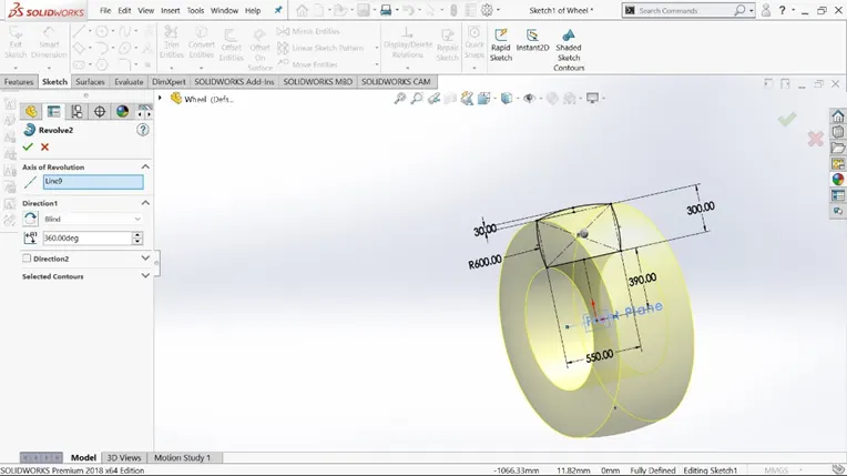
This feature works by selecting the axis of a sketch adding a round material by revolving around the selected axis. We can select an edge of a sketch if there is no axis.
Extrude cut:
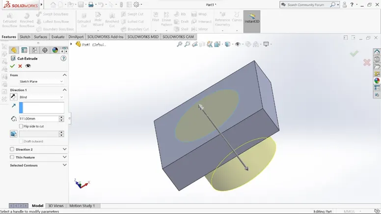
This feature allows you to remove unnecessary parts from the geometry or to give the desired shape to a sketch or solid part by sketching the solid part and then using this feature to get rid of that part.
Shell:
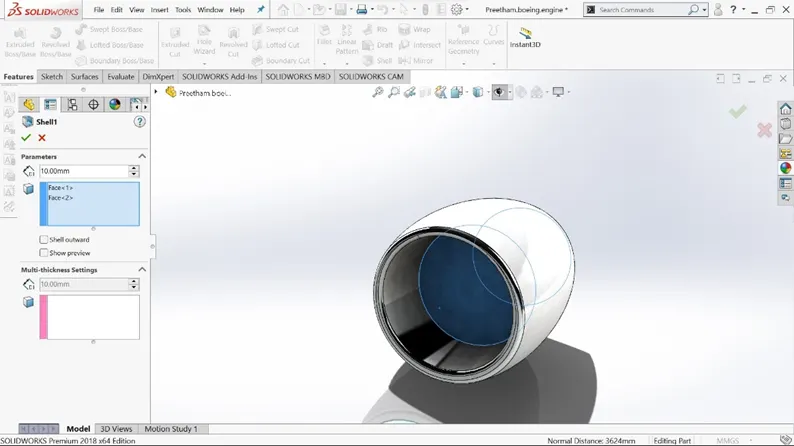
There is a very handy tool in SolidWorks that allows you to see what the inside geometry of a part will look like. In this tool, we add a thickness to the inside geometry and remove the material from the body so that the part appears hollow.
Linear pattern:
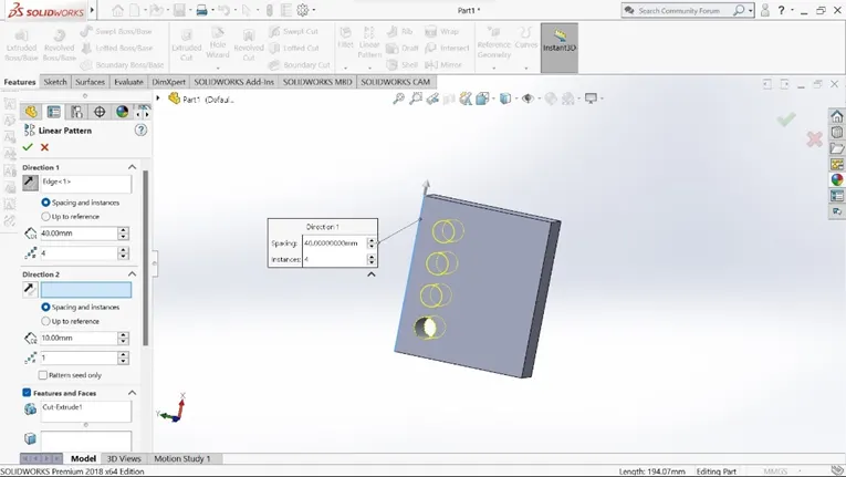
The linear pattern is a feature used to create a single sketch that can be used multiple times. The spacing, angles, and paths of this feature are given so that it can be used to draw or create a pattern This feature is spaced uniformly along one or two linear paths
Mirror:
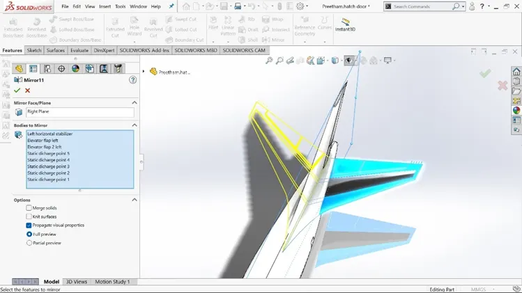
As this feature makes a copy of a solid part, it requires a plane or axis to mirror the part. Select the body to be mirrored, then choose an axis or plane, and then apply the feature. Multibody parts: Apply the feature to one or more multibody parts by selecting geometry patterns and using feature scope to select which bodies the feature should be applied to.
Reference Geometry:
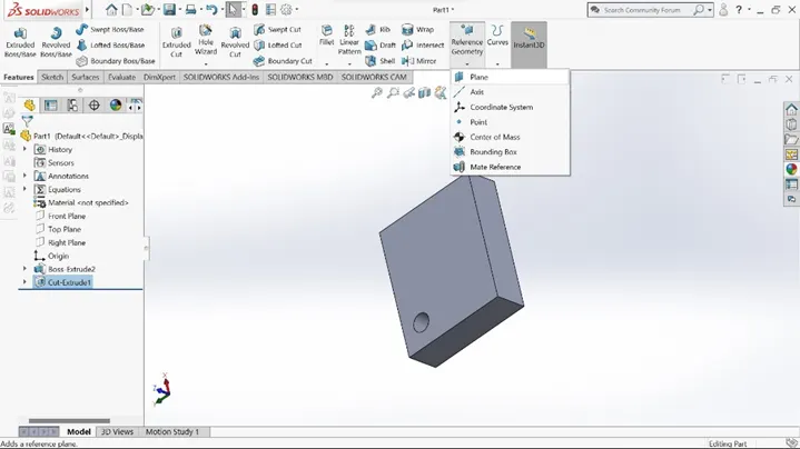
Surfaces and solids are defined by their shape or form. This includes planes, axes, coordinate systems, and points, which can be used in a sketch.
Use of Reference Geometry:
- Axis: If we want to pattern something and the axis is not available, then we can use the reference geometry axis to make it easier to do so.
- Plane: A reference geometry plane can be used to represent a plane when sketching and the sketch needs to be completed using a plane.
Projected Curve:
The curve can be projected by a sketch into a model to create a 3D curve We can create several closed or open contour projected curves from a single sketch Generally, the curve is the intersection of two extruding surfaces The curve which is created can be used as a path for the sketch of the part. Note: It does not create the curve of intersecting curves.
Knit:
Utilization of knit surface tools to combine two or more faces and surfaces into one. It creates a solid body when the knit surfaces form a closed volume or remain as surface bodies.
Mate:
Mates define a geometric relationship between assembly and component. When we add mates, they define the possible direction of linear or rotational motion for a component within its degree of freedom.
This feature includes:
- Coincident mate: Helps in making two planar faces to become coplanar which can be moved along one another but cannot be separated
- Concentric mate: Helps in making two circular faces concentric which can only be moved in the common axis
- Tangent: Helps in making a tangent mate between a face and plane
- Angular mate: Helps in making an angular relationship between a flat surface and the surface having some angle
Now let us see the above application of the features in the Boeing 747 that we have built which is discussed part by part
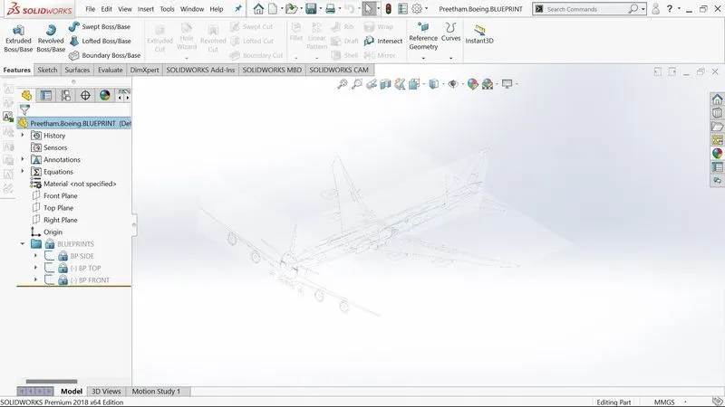
1. Blueprint
A blueprint is a two-dimensional series of drawings that shows how an architect envisions a project to look. Blueprints usually detail a structure's measurements, construction materials, and the precise positioning of all of its components.
When engineering designs were printed on blue paper with white lines in the mid-nineteenth century, the term "blueprint" was coined. Physical blueprints are seldom blue in the current building sector. Blueprints include construction drawings, construction plans, and working drawings.
- Side view of the aircraft > Tools > sketch tools > sketch picture
- Scaling the picture to 1:1, by setting up the length of the aircraft to 76.3 meters long
- Give transparency by clicking on the full image at the transparency section setting the value to .75
- Click on ok and rename to BP. SIDE
The above procedure is followed to set the blueprint of the Boeing 747 in top and front planes naming these sketch pictures as BP.TOP and BP. FRONT
2. Fuselage
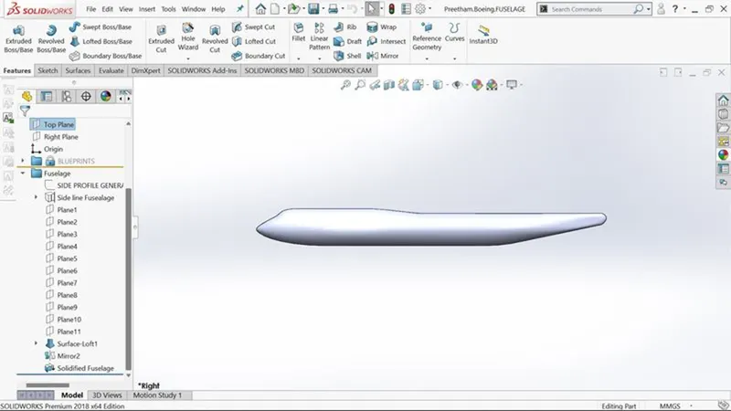
A fuselage is a structural structure that is designed to accommodate the engine, fuel, people, baggage, and mission-related equipment, but not usually at the same time. Thin sheets of material are strengthened by a large number of longitudinal stringers and transverse frames in aircraft fuselages. They often transport bending moments, shear pressures, and torsional loads, which cause axial and shear stresses in the stringers and skin, respectively; the stringers' resistance to shear forces is frequently overlooked.
- Outlining the side profile of the plane using the blueprint with the help of spile and line option on the right plane
- This sketch will be named as
- The new sketch is drawn on the right plane using the line and tangent arc option
- This sketch will be named as sideline fuselage side
- A new sketch is drawn on the top plane outlining the right side of the plane as per the blueprint
- The sketch will be named as sideline fuselage top
- The projected curve is added by selecting the 2 curves that are sideline fuselage side and sideline fuselage top
- The projected curves will be renamed as Sideline Fuselage
- Selecting the front plane 11 reference planes are made through the sketch
- Selecting the front plane and sketch is drawn by using the pierce option
- Plane 2 is selected and a spline is drawn with required weights and handles and piercing the endpoints of the spline with the Sideline Fuselage & Side profile general
- The above process is repeated to all the 11 planes
- Using the surface loft option, the above sketches are selected as profiles and the outlines as the guide curves
- The one side of the loft surface is mirrored on the right plane to create a whole body of the fuselage
3. Belly Fairing
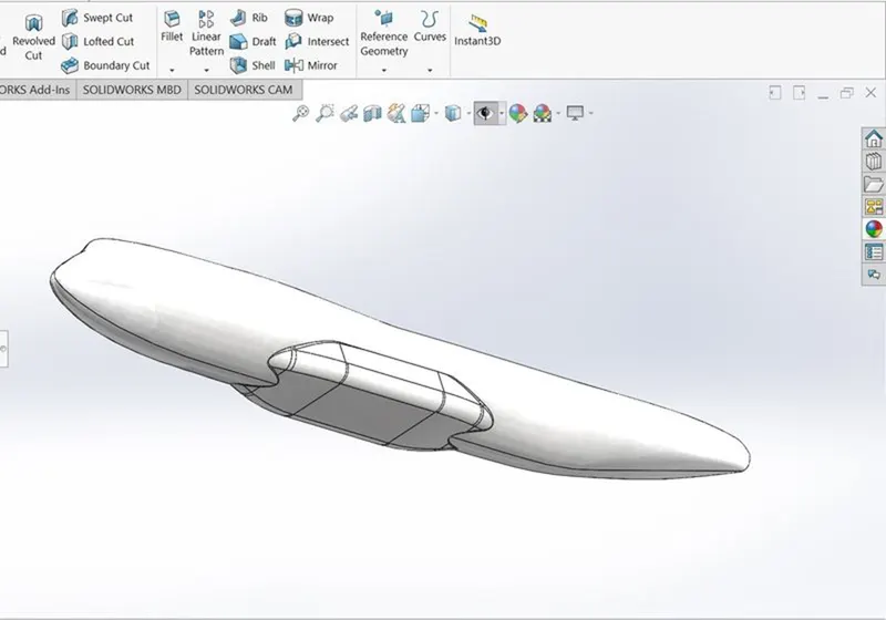
It is positioned on the bottom of the fuselage between the main wings and is sometimes known as a "ventral fairing." It can also be used to cover extra cargo storage or gasoline tanks.
- Select the right plane
- The belly fairing structure is drawn at the bottom of the fuselage as per the dimensions mentioned using the line sketch using the origin as the reference point
- The sketch is extruded to a distance of 3080mm and uncheck the merge result option
- Sketch the top plane, this sketch is drawn to trim excess part from the extruded boss
- Using the trim tool excess bodies will be consumed
- All the sharp edges will be smoothed using the fillet option
- The body will be mirrored using the right plane and merging the bodies to make it a one whole Belly fairing of the plane
- Fil
- let is be added between the fuselage and the belly fairing to give a smoother finish
4. Nosecone & Pitot tube
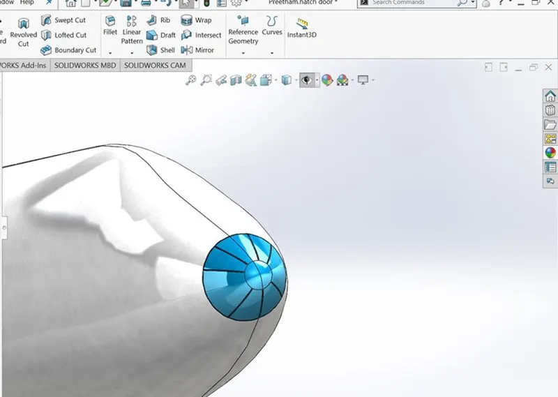
A nose cone is the forwardmost portion of a rocket, guided missile, or aircraft that is conically formed to regulate approaching airflow behavior and reduce aerodynamic drag.
- Select the right plane and click on normal
- Create a line at the top of the nose to the bottom of the nose and repeat this step 3 times as shown, these lines are given a distance between each other using the origin point as the reference
- Click on split lines, select the recently drawn sketch and select the two faces the lines needs to be projected to
- Select the front plane, draw a circle at the origin with the given dia, draw a line from the outer edge of the circle to the inner edge of the split line 3 lines are drawn using proper dimensions
- Select the split line option to select the recent sketch and the faces it has to split
- Sweep option is selected and circular profile is selected and split line are selected to pride a circular sweep path of required dimension
- The process is repeated to all the split lines as shown
- Select the right face and mirror the 3 swept features
- Fillets are put on the Edges of the swept surfaces to give a smoother surface
Pitot Tube
Pitot tubes are used to detect flow speed in wind tunnel research and aboard airplanes. It's a long, narrow tube with two openings. The front hole is inserted into the airstream to determine the pressure of stagnation. The static pressure is measured through the side hole.
- Select the top plane and a sketch is drawn with the reference from the origin as shown
- Select right plane for a new sketch, using lines and split line option below the cock pit area using the origin as the reference point for dimension
- Extrude the above-drawn sketch, using extrude from surface/face/plane option select the face of the fuselage,
- Select the first sketch drawn as direction, uncheck the merge result option
- Axis is drawn using Two points/vertices on the extruded surface
- The plane is put using the reference point as the axis drawn above and the right plane
- Select the newly created plane and the line is drawn along the axis as per the dimensions mentions
- Select the sweep option and select the circular profile using the sketch as the swept surface.
- The above process is repeated with the second pitot tube
- Champer command is put on the edges of the pitot tube
- Select the front face of the pitot tube and draw a circular sketch
- Select the extrude cut option and cut up to a certain distance, this hole is used for the air to pass through the pitot tube and to calculate the pressure
- The process is repeated with the second pitot tube as well
- Using the mirror option these bodies are mirrored to another side of the fuselage using the right plane as the reference plane
- Cockpit windows, Windshield wipers & Passenger windows
Cockpit windows
The cockpit is the part of the aircraft that offers visibility to the front and sides and houses the pilot(s) and other crew members A sun shield may be installed in the cockpit windows. When the plane is on the ground, most cockpits include windows that can be opened. Anti-reflective coatings are applied to nearly all glass panes in big airplanes, and an internal heating element is used to melt ice.
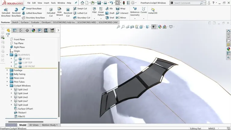
- The new sketch is drawn on section plane 5, with the help of wireframe visibility and blueprint using the line and spline option cockpit window is drawn using the origin as the reference point for dimension
- The split line option is activated by selecting the above-drawn sketch and selecting the front face of the fuselage and enabling one direction only
- Selecting the right plane side windows of the cockpit is drawn as per the dimension of the blueprint and spline line function is activated this time on both the sides
- Another sketch is drawn on plane 5 to make the frames of the cock pit, by using the offset option towards the inside of the sketch drawn and spilled line feature is enabled selecting the small inner faces of the cockpit
- The same process is repeated on the right plane to make the frames of the side cockpit windows
- Glass appearance will be added to the faces of the cockpit window area
- Select the frames of the cockpit window and activate the offset surface with the offset value of 10mm
- Select the offset surface and enable thicken surface option towards the outside and give a value of 5mm and deselect the merge result option
- The fillet option is enabled by selecting the surface of the frame of 4mm to remove the sharp edges
Windshield wipers
The wipers are potentially useful for Ground operations, take-offs, and landings that might all benefit from the wipers. They, like our automobiles, have multiple speed settings. The two wipers work separately, allowing the pilot and co-pilot to manage their windscreen.
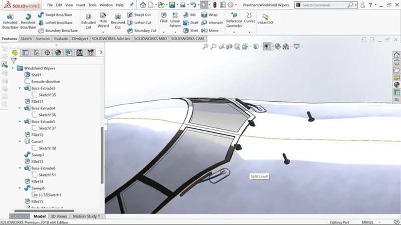
- Create a new sketch in the right place at the nose section
- Create a new sketch on the top plane using the ellipse option at the nose section
- The above sketch is extruded from the surface/face/plane option selecting the first sketch drawn in the right place as the guide direction and deselecting the merge option and clicking on accept
- The new sketch is drawn at the top plane on the surface of the nose using the circle option with a specified dimension
- The above sketch is extruded from the surface/face/plane option selecting the first sketch drawn in the right place as the guide direction and deselecting the merge option and clicking on accept
- The new sketch is drawn on the face of the above-extruded surface, draw a circle of specified dimension and the sketch is extruded from the surface/face/plane option selecting the first sketch drawn in the right place as the guide direction and selecting the merge option and click on accept
- Fillet is provided on the edges of the circular extruded to provide a smoother surface edge
- A new sketch is drawn on the top plane using the offset option outer edge is offset to a distance of 40mm and projected on the surface using the project curve option
- The projected is used a circular path for the swept surface option and will be used as wiper blades
- Create a new sketch on the top plane using slot option angling between the center of the fuselage and the slot center axis
- The above sketch extruded from the surface/face/plane option with a height of 10mm and deselect the merge option.
- Fillet is put on the top surface of the extruded slot to give a smoother edge
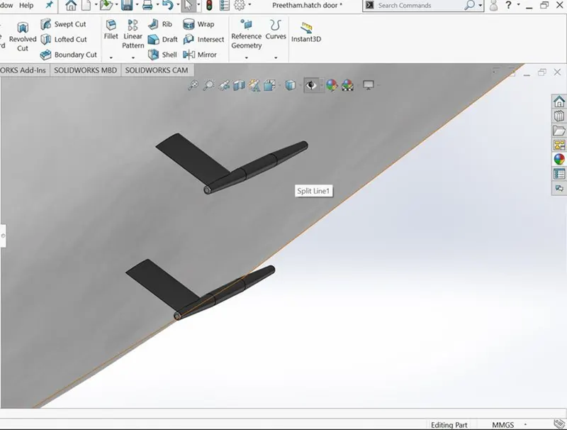
- Using the 3D sketch option, the wiper arm is drawn as shown using the spline option
- A swept boss is activated using a circular path and a merge option is activated merging the wiper body
- Go to insert >feature >move/copy move the wiper body a slight upwards as shown
- Select the right plane as a reference and mirror the bodies to the other side of the fuselage
Passenger windows
An airplane's windows are divided into three sections: inner, middle, and outside. The outside pane absorbs the pressure, the middle works as a fail-safe, and the inner pane is only there to protect the other two from passengers. The hole also allows moisture to escape from the gaps, preventing fogging or freezing of the windows.
- Sketch block is created of passenger shaped windows
- Create a new part and select the front plane to sketch the windows
- Open the fuselage model and select the display type as wireframe
- Select the right plane and click on the sketch
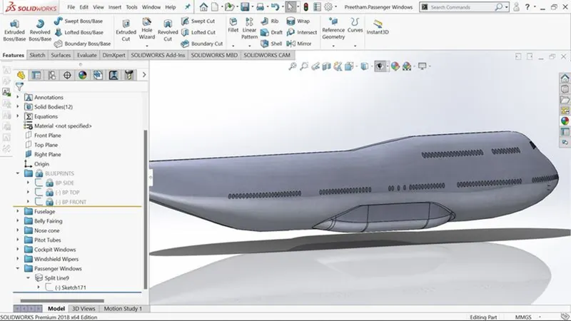
- Insert tool > blocks > insert blocks, select the above-prepared block and place it on blueprint where the passenger windows are shown
- Using linear pattern multiple windows are placed along the selected direction, using instances to skip option we can remove the unnecessary mirrored blocks
- The process is continued until all the passenger windows are placed as per the blueprint
- The split line feature is selected by using the sketch drawn on the earlier step and selecting the faces of the fuselage
- the inside face will be adding an appearance of clear glass with tinted black color outer faces/ window frames will be given an appearance of polished silver
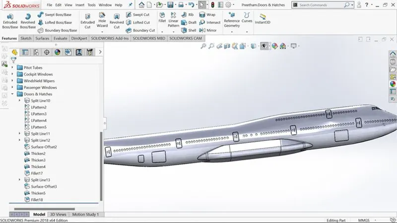
- Doors and Hatches
Doors
On a plane, there are three sorts of doors: passenger exits, service doors, and emergency exits. The front, middle, and rear regions of large passenger aircraft have the most passenger doors utilized during boarding. Passengers can board planes through several entrances thanks to these doors.
- Open the fuselage model and select the display type as wireframe
- Select the right plane and click on the sketch
- Sketch the door as mentioned using the front plane as a reference for dimension
- Using linear pattern multiple doors are placed along the selected direction, using instances to skip option we can remove the unnecessary mirrored blocks
- The process is continued until all the doors windows are placed as per the blueprint
- The split line feature is selected by using the sketch drawn on the earlier step and selecting the faces of the fuselage
Hatches
Select the right plane for a new sketch using the display as wireframe, hatches are drawn using the line and spline option using the blueprint as the reference for the design and the origin as the reference for the dimension
- Fillets are added to the sketch to give a smoother design on the edges
- The offset of the sketch is created towards the inside of 50mm
- Using the split line option, the above-drawn sketch is elected and the face of the fuselage is selected depending on where the hatches are described in the blueprint
- Select the frames of the hatches and activate the offset surface with the offset value of 0mm
- Select the offset surface and enable thicken surface option towards the outside and give a value of 8mm and select the merge result option
- The fillet option is enabled by selecting the surface of the frame of 7 mm to remove the sharp edges
- Escape hatch sketch is made on the top plane using the rectangular feature and creating an offset inside to make the frame for the hatches and with the split line feature and selecting a single direction that is upwards the hatch is made
- Select the frames of the hatches and activate the offset surface with the offset value of 0mm
- Select the offset surface and enable thicken surface option towards the outside and give a value of 8mm and select the merge result option
- The fillet option is enabled by selecting the surface of the frame of 5 mm to remove the sharp edges
- Lighting, Antennas & Auxiliary Power unit
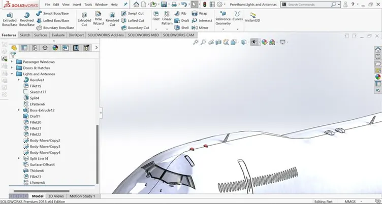
Lighting
Anti-collision lights, also known as Beacon lights or Strobe lights, are a set of lights that must be installed on every aircraft to increase visibility to others and to prevent collisions by alerting other pilots. In the past, incandescent bulbs were utilized, but more recently, light-emitting diodes have been employed.
- The new sketch is drawn on the right plane behind the cock pit
- Revolve boss base feature is enabled and the axis of rotation is given at the straight line of the sketch to make sure the merge result box is unchecked
- Fillet of 20mm is given to give a smoother finish
- Select the right plane and draw a line to split between the light and the body
- Using the split tool, select the above sketch and click on cut bodies make sure consume bodies is unchecked
- Select the light and add the appearance of clear glass red color and body as polished silver
- Using the liner pattern and selecting the front plane as direction second light body is created
Antenna
An aircraft antenna is a device that is used to navigate the aircraft by using radio frequencies. It is used to communicate with other aircraft as well as ground-based control stations. Navigation and communication are the prime applications of aircraft antennas.
Wing antenna
- The new sketch is drawn on the right plane to create an antenna as mentioned using the origin as the reference point
- Using extrude boss base from midplane a body is created
- Using draft feature shape of the antenna is given following with the fillet on the edges
- With the help of the move copy feature, will be moving the copy body to a different location with the help of the translate option
Slot antenna
- Select the top plane and a sketch of the slot antenna is drawn using the origin as the reference for the dimension
- Using the split line option, the above-drawn slot is selected and enabling only one direction option and selecting the faces of the fuselage
- This split feature will be enabled with an offset feature of 0mm, thicken feature is enabled of 120mm, and uncheck the merge result
- Fillet of 115mm is given on the edge to give a smoother edge
- Using linear pattern will be duplicating the body
Auxiliary
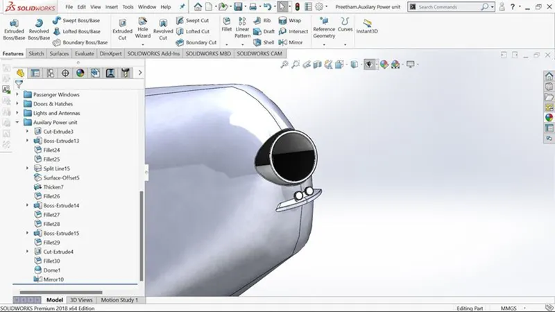
The auxiliary power unit (APU) is a tiny gas-turbine engine installed in an aircraft's tail cone that provides independent electrical and mechanical power for The primary engines' starting power. For cabin air conditioning systems, pneumatic power is used.
- Select the front plane, to view the backside of the fuselage
- The sketch is drawn on the centerline of the fuselage directly above the origin using the circle option using the origin as the reference for dimension
- Extrude cut option is enabled using offset feature, unselect all bodies and manually select the fuselage
- A new sketch is drawn on the front plane and click on normal to view the backside of the fuselage
- Create 2 circles concentric to each other giving a proper dimension as mentioned
- Extrude boss base and select offset feature and make sure the merge result is unchecked and click ok
- Apply feature of polished silver to the auxiliary power unit
- Apply fillet to the circular edge of the fuselage
- Vertical, Horizontal stabilizer & Wings
Vertical Stabilizer
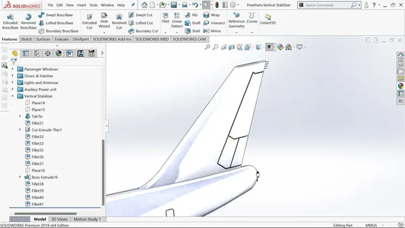
The vertical stabilizer is a component of an airplane that is commonly referred to as a "vertical tail" by many people. It's found on the back of an airplane's fuselage and extends vertically.
- New sketch on the right plane using the line and spline option taking the blueprint as the reference of the vertical stabilizer using the origin as the reference point
- The above sketch is named as side view front tail
- A new sketch is drawn on the right plane using spline and line option of the backside of the vertical stabilizer
- The above sketch is named as side view tail rear
- the new reference plane is made by selecting the top lane and 2nd vertex point as the side view front tail top endpoint
- the new reference plane is made by selecting the top lane and 2nd vertex point as the side view front tail lower endpoint
- a new sketch is drawn on a new upper plane connecting the 2 top end sketches by an axis use the spline option to create the rest of the sketch with required weights and angles and another section is mirrored from the axis reference point
- the new sketch is drawn on the lower plane connecting the 2 top end sketches by an axis use the spline option to create the rest of the sketch with required weights and angles and another section is mirrored from the axis reference point
- Loft boss base feature is enabled by selecting profiles as the upper and lower sketches and guide curves as side view front tail and side view tail rear
- Fillets are provided to smoothen the sharp edge surface
- Hide the vertical stabilizer body so that we can see the blueprint for drawing the lines
- Using the right plane we will be drawing the rudder edges as shown in the blueprint using the line option taking the origin as the reference for the dimension
- Cut extrude feature is selected since the above sketch is an open sketch by default it will take as the thin feature selecting the midplane direction, make sure to unselect auto bodies and select vertical stabilizer
- Fillet is given to the sharp edges to give a smoother surface
- The new sketch is drawn on the front plane and click on normal to the backside of the fuselage,
- Circles are drawn at the center of the fuselage body at the top of the vertical stabilizer,
- Linear pattern feature is used to create 5 such circles at a certain distance from each other
- Boss extrude feature is enabled from the surface/Face/Plane option and uncheck the merge result
- Fillets are given to each of the edges to give a smoother edge
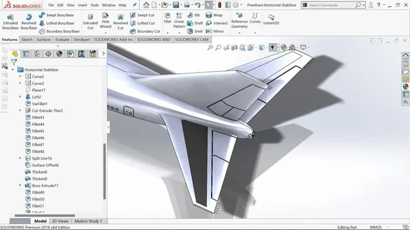
Horizontal Stabilizer
Most planes have a horizontal stabilizer and an elevator at the back of the fuselage. The stabilizer is a fixed-wing piece whose purpose is to keep the plane flying straight by providing stability. The horizontal stabilizer stops the aircraft's nose from tilting up and down vertically.
- New sketch on the top plane using the line and spline option taking the blueprint as the reference of the horizontal stabilizer using the origin as the reference point
- The above sketch is named as Tail wing top view
- The new sketch is drawn on the front plane using spline and line option projecting the line at an angle from the front plane
- The above sketch is named as tail wing front
- Using the projected curve option select the two sketches
- The new sketch is drawn on the top plane using spline and line option of the backside of the horizontal stabilizer
- The above sketch is named as Top wing top rear
- Using the projected curve option select the recently drawn sketch and tail wing front
- These projected curves will be used as guide curves for the surface base loft
- the new reference plane is made by selecting the right plane and 2nd vertex point as the first projected curve outed endpoint
- a new sketch is drawn on a new outer plane connecting the 2 top end curves by an axis use the spline option to create the rest of the sketch with required weights and angles and another section is mirrored from the axis reference point
- a new sketch is drawn on the right plane connecting the 2 inner end curve points by an axis use the spline option to create the rest of the sketch with required weights and angles and another section is mirrored from the axis reference point
- Loft boss base feature is enabled by selecting profiles as the inner and outer sketches and guide curves as the two projected curves
- Fillets are provided to smoothen the sharp edge surface
- Hide the horizontal stabilizer body so that we can see the blueprint for drawing the lines
- Using the Top, we will be drawing the flap edges as shown in the blueprint using the line option taking the origin as the reference for the dimension
- Cut extrude feature is selected since the above sketch is an open sketch by default it will take as the thin feature selecting the midplane direction through all both, make sure to unselect auto bodies and select horizontal stabilizer
- Fillet is given to the sharp edges to give a smoother surface
- A new sketch is drawn on plane 10 and zoom in on the horizontal stabilizer draw an axis at the midplane of the horizontal stabilizer which will be used as the intersection point of the static points
- Circles are drawn at the center of the axis.
- Linear pattern feature is used to create 5 such circles at a certain distance from each other
- Boss extrude feature is enabled from the surface/Face/Plane option and uncheck the merge result and deselect auto bodies and select the horizontal stabilizer
- Fillets are given to each of the edges to give a smoother edge
- The horizontal stabilizer is mirrored to the other side of the fuselage taking the right plane as the reference point
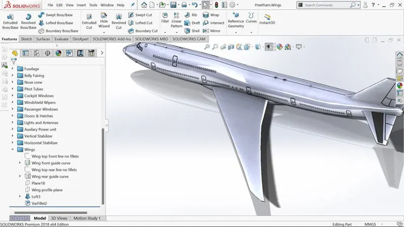
Wings
- New sketch on the top plane using the line and spline option taking the blueprint as the reference of the horizontal stabilizer using the origin as the reference point
- The above sketch is named as Wing top front line no fillet
- A new sketch is drawn on the top plane pre-select Wing top front line no fillet and converted to entities
- Give a fillet on the intersection of 2 spline points of 400mm
- The above sketch is named as Wing top front-line fillet
- A new sketch is drawn on the front plane consisting of 2 splines meeting the endpoint of the origin and 2ndspline meeting the first spline and the tip of the wing
- The above sketch is named as Wing front line
- Using the projected curve option select the two sketches Wing front line and Wing top front-line fillet
- Rename the projected curve as Wing front guide curve
- A new sketch is drawn on the top plane using spline and line option of the backside of the wing
- The above sketch is named as Wing top rear line no fillet
- A new sketch is drawn on the top plane pre-select Wing top rear line no fillet and converted to entities
- Give a fillet on the intersection of 2 spline points of 10000mm
- The above sketch is named as Wing top rear line fillet
- Using the projected curve option select the two sketches Wing front line and Wing top rear line fillet
- Rename the projected curve as Wing rear guide curve
- a new sketch is drawn on the right plane connecting the 2 inner end curve points by an axis use the spline option to create the rest of the sketch with required weights and angles and another section is mirrored from the axis reference point
- the new reference plane is made by selecting the right plane with an offset of 15000mm
- a new sketch is drawn on new outer plane connecting spline is drawn where the endpoints meet the 2 guide curves spline handles and axis is also drawn for reference the splines are activated and vertical relation with weights are enabled another section is mirrored raking the axis reference line
- A new reference plane is created by selecting the right plane and 2ndvertex point as the first projected curve of the outer end
- a new sketch is drawn on a new outer plane connecting the 2 projected curves by an axis use the spline option to create the rest of the sketch with required weights and angles and another section is mirrored from the axis reference point
- Loft boss base feature is enabled by selecting profiles as the inner, middle, and outer sketches and guide curves as the two projected curves make sure the merge result is unticked
- Fillets are provided to smoothen the sharp edge surface
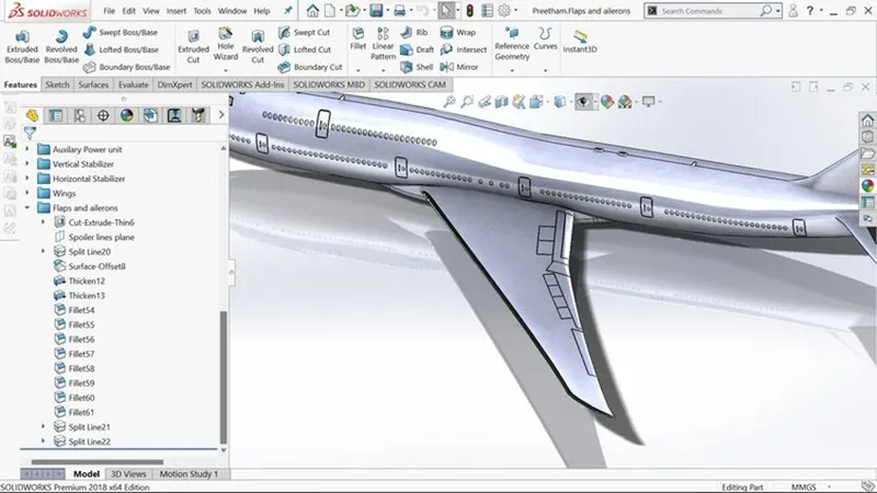
- Flaps and Ailerons
Flaps
A flap is a high-lift device that reduces an aircraft wing's stalling speed at a given weight. Flaps are often attached to the trailing edges of a fixed-wing aircraft's wings. Flaps are used to shorten the distance between take-off and landing.
Ailerons
The pilot controls the aileron, which is a moveable component of an airplane wing that allows him to roll the plane about its longitudinal axis. As a result, ailerons are generally utilized to bank the aircraft for turning.
- Hide the wing-body so that we can see the blueprint for drawing the lines
- Using the Top, we will be drawing the edges and ailerons as shown in the blueprint using the line option taking the origin as the reference for the dimension
- Cut extrude feature is selected since the above sketch is an open sketch by default it will take as the thin feature selecting the midplane direction through all both, make sure to unselect auto bodies and select wing as the body
- A new sketch is drawn on the top plane to make the spoiler plane and the speed brake as shown
- Go to the features split line and select the face of the wing
- Select the split line section of the spoiler and the speed brakes and activate the offset surface with the offset value of 0mm
- Select the offset surface and enable thicken surface option towards outside and give a value of 10mm and select the merge result option
- The fillet option is enabled by selecting the surface of the thickening surface of 9 mm to remove the sharp edges
- Fillet is given to the sharp edges of the flaps and ailerons to give a smoother surface
- The horizontal stabilizer is mirrored to the other side of the fuselage taking the right plane as the reference point
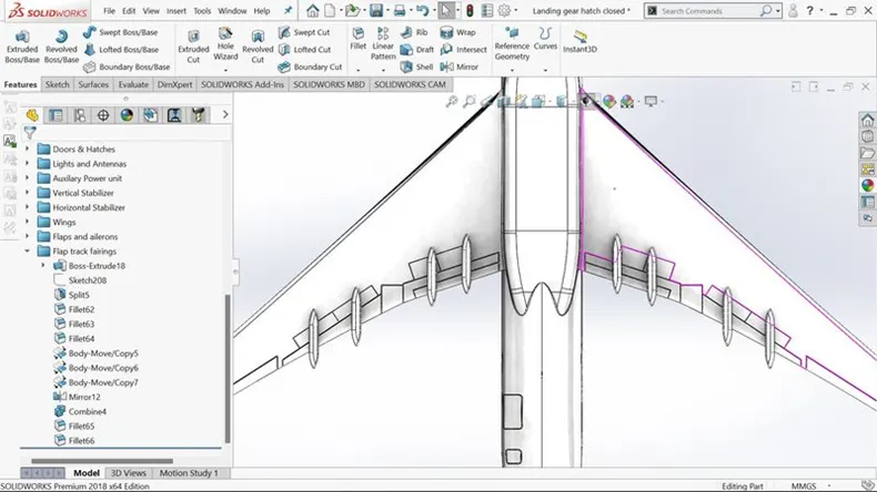
- Flap track fairing:
A flap track fairing is a supplementary construction that reduces drag by providing an aerodynamic cover. These structures hide gaps and voids between aircraft elements, reducing form drag and interference drag while also improving aesthetics.
- A new sketch is drawn on the top plane using the spline and line option, based on the design of the blueprint and taking origin as the reference for Dimension
- The above sketch is extruded at an offset of 400mm and uncheck merge result, make sure the extrude direction is downwards
- Select the side face of the extruded surface and click on a new sketch
- Draw centerline axis between the extruded surface vertically and horizontally and 3 plane arc is drawn where the midplane touches the endpoint of the centreline mirror the bottom sketch to the other half using the horizontal axis as the reference sections
- Select split option, select the above sketch and select the above-extruded body and click on cut bodies, select the bodies which are unnecessary and check the consume bodies option and click on ok
- Fillet is given to all the sharp edges to give a smoother finish
- Using the move/copy feature will be copying the created body and placing it to other parts of the wings
- After finishing the one side of the wing, using the mirror option and taking the right plane as a reference will be mirror another side of the wing
- Combine feature is enabled and we select the 2 wings and the fuselage to make it into a single part
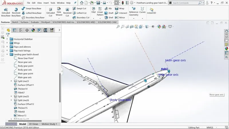
Landing gear axis
- Will begin the first sketch on the right plane,
- Insert an endpoint right behind and below the cock pit using the origin as the reference for dimension
- I will be named as nose gear point
- Let’s create an axis, using point and face /plane
- Will name the axis as nose gear axis
- The next sketch will be on the right plane
- We will be inserting the right plane near the wing side
- Will name the axis as body gear point
- Let’s create an axis, using point and face /plane
- Will name the axis as body gear axis
- New sketch on a front plane using the centreline option below the origin of the right plane
- Let’s put an endpoint at the end of the centerline using the origin as the reference
- Let’s name the sketch as the main gear point
- Let’s create an axis using point and face /plane
- Will name the axis as the Main gear axis
- Landing gear hatches Open & Closed
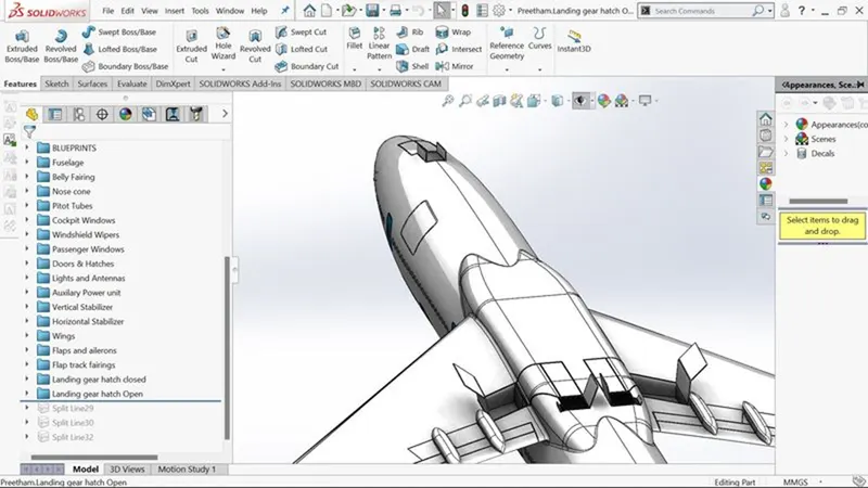
Landing gear hatches open
- A new sketch is drawn on the top plane, using the rectangular option drawing from within the inner edges of the bottom closed hatch of the front section
- Extrude cut through the body pointing downwards
- Create a plane for the hatch, select the inner vertex point and the following edge as the 2nd vertex to create a plane
- Sketch a line vertically on the new plane using the line option
- Using swept surface feature select the above sketch as the profile and the following edge as the swept path
- Thicken surface of 30mm and deselect merge option and click on ok
- Fillet of 10mm is given on the edges to give a smoother surface
- When one of the hatches are done mirror the hatch to the other side of the fuselage and use a right plane as the reference
- The same procedure is followed to create an open hatch section at the wing section of the plane
- Extrude cutting the outer parallelogram section offsetting a distance from inside the wing
- A new plane is created selecting the vertex point and the edge as the 2nd vertex point
- Draw a parallelogram where the endpoints touch two endpoints of the extruded cut section as shown
- Extrude the surface of a distance of 60mm from midplane and click on ok
- Create a new plane by selecting the two edges of the extruded surface as shown
- Draw a parallelogram where the endpoints touch two endpoints of the extruded surface shown
- Extrude the surface of a distance of 60mm from midplane and click on ok
- Apply fillet to give a smoother edge
- The above procedure is followed to create another hatch section as shown
- Once all the open hatch sections are done, they will be mirrored to other sections of the plane using the right plane as the mirror reference plane
Landing gear hatches closed
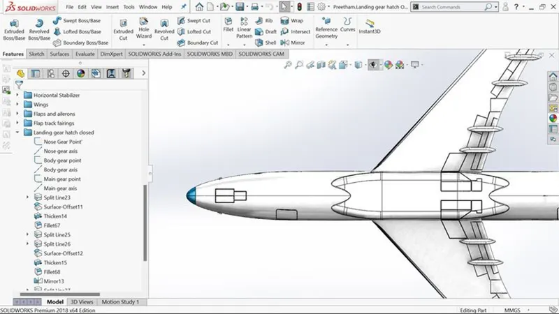
When the plane is parked, taxiing, taking off, or landing, the landing gear is the primary support. Wheels are the most typical landing gear, although airplanes can also be outfitted with floats for water operations or skis for snow landings.
- The new sketch is drawn on the top plane and click on normal to view the bottom of the plane
- Zoom towards the nose section of the plane
- The sketch is drawn using the rectangular section and offsets inwards to make a frame-like structure using the origin as the reference for dimension
- Enable the split line feature and select the sketch and faces to be projected, select the single direction and make sure to be projected below the plane
- Enable offset surface with the offset value of 0mm
- Select the offset surface and enable thicken surface option towards the outside and give a value of 20mm and select the merge result option
- The fillet option is enabled by selecting the surface of the thickening surface of 10 mm to remove the sharp edges
- Let’s split the wing into two parts by sketching on the front plane selecting the upper of the wing and converting them as offset entities towards the inside of the wing
- Enable split line feature and split the wing into two parts
- Follow the same procedure to create hatches at the bottom near the wing section as per the blueprint
- After creating a closed hatch on side of the plane will be mirroring the closed hatch to the other side of the plane using the right plane as the reference plane
- Wheel
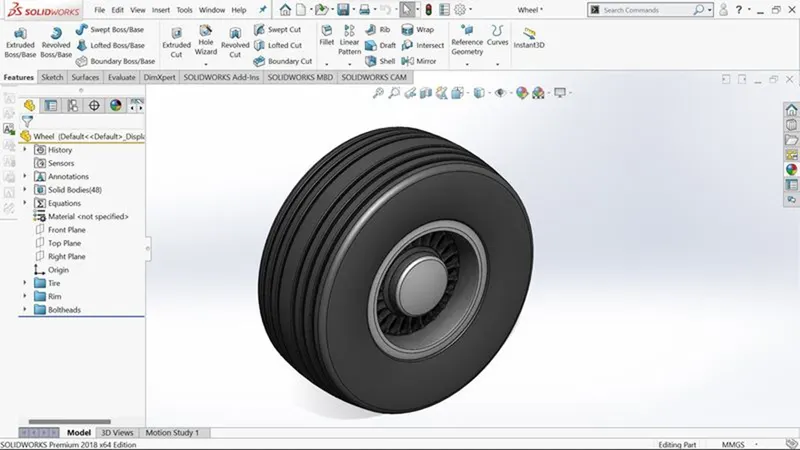
Commercial airline planes often have ten or more wheels since they must sustain massive weights when taxiing, at rest, and during takeoff and landing. Light aircraft, on the other hand, may get away with only having three wheels to support their tiny frames and bodies.
- Select the front plane and start a new sketch
- Using line axis and tangent arc a section of the tire is drawn
- Using revolved boss feature the above sketch is revolved up to 360 deg
- Select the front plane to draw thread using the reference of the outer edged of the tire by creating an offset of particular distance a thread design is created
- Using the cut revolve option the above-drawn sketch is cut across the earlier created tire body at an angle of 360 deg
- Fillets are provided across the face of the thread slots as shown
- Another fillet of 10 is given on the inside face of the tire
- Use the shell of 50mm on the inside face of the tire
- Add an appearance of matt rubber on the body
- will create a section view on the front plane and click on normal to
- a new sketch is drawn on the front plane from the left-hand side to the vertical line a make sure the endpoint of the line intersects the inner portion of the tire using the pierce option
- hide the tire body and begin to draw the portion of the rim, draw the geometry as shown using the origin as the reference point
- create a revolve Bose base select the horizontal line at the origin as the centerline of axis
- create a dome 20mm ar the center as shown
- apply fillet to the dome section to remove the sharp edges
- will be adding champers at the inner edge of the rim
- a new sketch is drawn on the right plane making it normal to towards the front side of the rim
- will be drawing the patterns inside the mirror to reduce the weight of the rim using the spline and line option
- selecting the extrude cut above sketch is cut from the body
- using a circular pattern will repeat the above extrude option with an instance of 23 of equal spacing and select on ok
- the rim is later mirrored on the other side using the back face of the part as the reference plane and click on merge solid
- show the solid body that represents the tire
- a new sketch is drawn on the right plane using the circle option to create a nut and bolt option using the extrude cut and extrude boss option
- the above-created nut and bolt option is later inserted on the other sides using the circular pattern option
- Nose Gear base, suspension arm & Assembly
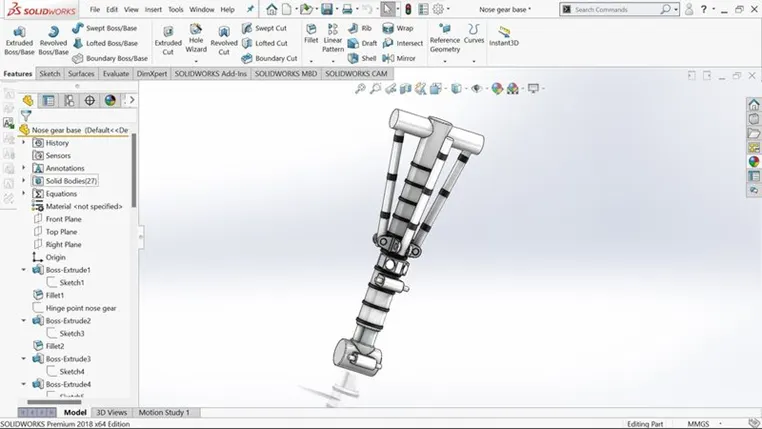
The landing gear at the nose of an airplane is referred to as nose gear. The wheel, tire, and components in the front of the plane are referred to as nose gear in any type of airplane with a tricycle style of the landing gear.
- Start a new sketch on the right plane using a circle and taking origin as the reference for the dimension
- The above sketch is extruded to create a body
- Apply fillet to both the face of 10mm
- Select the right plane to create a new sketch on the normal view
- Start a new sketch using the centerline of a distance of 3000m create an endpoint at the end of the centerline
- I will be naming the point as hinge point nose gear
- Create a new sketch on the top plane using a circle at the origin
- Extrude the sketch to up to 200mm keeping the merge option on
- Add a fillet to the design at the top face of the extrude
- Create a new sketch on the top face click on offset and bring the edge inwards 15mm
- We will be using extrude to a distance of 200mm and deselect the merge option off
- Create a new sketch on the top face of the extrude
- Use the offset option with a distance of 25mm outside and say ok
- Using extrude option we are extruding the above sketch to a distance of 2750mm
- Apply the fillets on the outside edge
- Select the bottom face of the and create a new sketch
- Grab the outer edge and click on convert entities and select an offset of 15mm
- Use the extrude boss base one more time select the offset option and add a value of 40mm change the extrude distance to 35mm and deselect the merge option
- Apply a filet of 3mm on the face of the extruded surface
- Create a linear pattern of a distance of 230mm selecting the vertical axis no of instance will be 10 and selecting the extruded body.
- Click on the right plane and start a sketch
- Select the slot and drag it outside from the origin
- Create an extrude the from the midplane direction
- Select the end face and create a sketch
- Select the circle tool make sure it is concentric to the outer radius
- Extrude a distance of 90mm select the body as the new extruded body
- Create a mirror using the right plane and mirror the recent extrude
- Add fillet on both sides and edges of the recently extruded bodies
- Let’s create a linear pattern with a distance value of 1030mm and the direction will be the vertical axis and select the recently extrude bodies
- Insert feature and combine, will be combining extruded body to the main body
- Add fillet at the point of intersection of the extruded bodies
- Create a new sketch on the front plane
- Create a rectangle using the center point line and snap to the vertical line and use our smart dimension tool
- Create an extrude of a distance of 320mm
- Add champers to the extruded body of 120mm and an angle of 45deg
- Apply a fillet to give a smoother finish
- Select the face and create a sketch
- Create sketch line snapping from the lower-left corner to the above right corner
- Create a circle of 140mm at the center of the sketch line
- Extrude the above sketch of 5mm and deselect the merge option
- Insert a dome of 20mm on the outer surface
- Go to insert feature and add a fillet between the dome and the original extrude and click on ok
- Select the back face to create a new sketch
- Create a circle concentric to the extruded body
- Spilled the outside face using the split line option
- Create a mirror using bodies to mirror using the right plane as the reference
- Let’s create a new sketch on the front plane using the line option snapping to the vertical axis line and adding a smart dimension
- Create an extrude of an offset of 80mm up to a distance of 40mm and apply a fillet of 75mm
- Create a new sketch on the outer face and draw a circle concentric with the outside arc
- Use extrude cut option and select on through all and apply fillet on the outside and the inside face
- Mirror the above body using the right plane
- Create a circular pattern with an angle of 180 deg and select both the bodies and select ok
- Combine the body of all the tabs and the main body
- Create a new sketch on the front plane using the line tool from the center of the circle of the tab towards the left
- Go to sketch create an insert sweep select circular profile and add a dia 0f 120mm
- Select the end face of the sweep and click on convert entities and create an offset of 20mm
- Extrude the sketch with an offset of 200mm with an extrude length of 80mm deselect merge result option and click on ok
- Add a fillet of 3mm and select the outside face of the extruded body
- Select a linear pattern of 3 instances of a distance of 490mm
- Create a circular pattern of 180 deg and an instance of 3 and click on ok
- Create a new sketch on the right plane, snap a circle to hinge point nose gear, and pierce the option
- Extrude to a direction of 1200mm from the midplane direction
- Rename the body as nose gear axis
- Apply the appearance as required
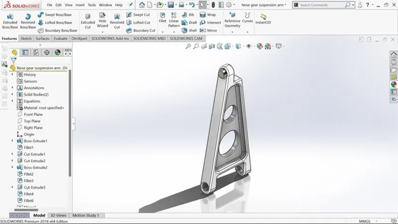
Nose gear suspension arm
The control arms are one of the most important parts of a suspension system since they connect the front wheel assemblies to the vehicle's chassis directly.
- Create a new part design, using the front plane using the line and smart design option
- Extrude is a mid-plane direction using a distance of 100mm,
- Apply a fillet of 50mm to the upper edge as shown as well as the bottom edge
- Will create a new sketch on the front plane using a rectangular option at the top right and the bottom points
- Select the extrude cut tool and select cut through all in both directions
- Select the inside face of the upper portion. Will start creating a circle that is concentric towards the upper arc
- Use extrude cut option and select through all option
- Select a new sketch on the face and select the extrude cut and click on convert entities
- go to extrude option and extrude through a direction on 90mm which is passing through the extruded cut section
- apply fillets to the sharp edge sections to reduce the area of stress
- create a new sketch on the outside face of the part offset the outer edges towards the inside
- extrude cut a distance of 30mm
- use a fillet tool of 40mm to all the internal corners of the extrude
- apply fillet to give smoother edge corners
- select the front plane as mirror plane, selecting the extrude and fillet option details
- create a new sketch on the inner face, using the circle and smart dimension
- extrude cut through all on both the direction and apply filler
- select the bottom inside faces and create a new sketch
- crate a circle concentric towards the lower arc
- and apply appearance option
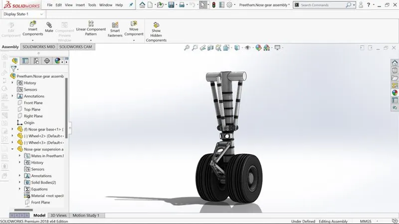
Nose gear assembly
- Create a new assembly
- Browse the files starting with nose gear base
- Insert another component going with wheel
- Go to insert component and add another wheel
- Go to mate and select concentric and select outside of the wheel and the cylinder and click on ok
- Same mate operation is carried out on the other side of the wheel
- Add another component called nose gear suspension twice
- Apply concentric mate on the pivot point of the arm and the upper pivot point on the suspension nose gear base and apply a coincident mate
- Same mate operation is applied but on the lower pivot point on the suspension nose gear
- Add concentric mate between the pins of the suspension arm
- Apply axis on the upper cylinder and rename as nose gear axis
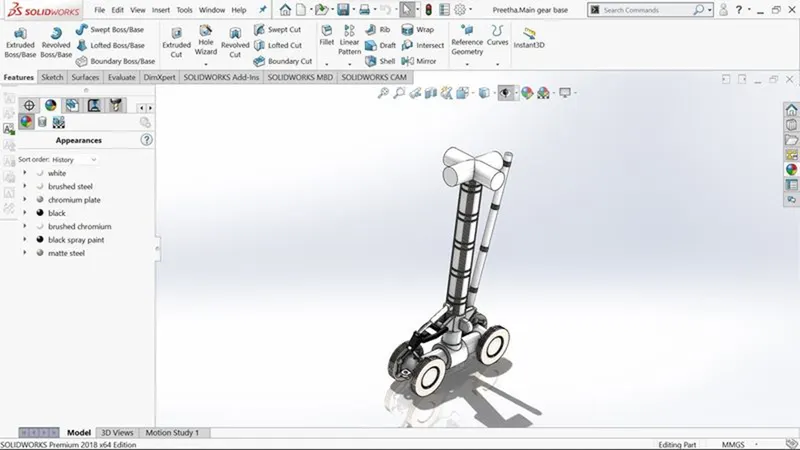
- Main Gear Base, suspension arm & Assembly
Main Gear Base
- create a new sketch on the front begin with a circle at the origin and simply drag it up and use the smart dimension tool to give it a diameter value of 300 mm
- go into the features extrude option and we’re going to add a value of 1500 mm
- select the right plane and start a new sketch using the normal 2 option and using a circle tool we’re going to snap to the midpoint of both ends and simply create a circle that is larger than the original extrude then using are smart dimension tool we’re going to apply a diameter value of 350 mm
- we can select the extrude of a distance value to 600 mm make sure that we rotate this around to ensure that is going both directions and say okay by default it will merge
- select the end face of this to start a new sketch and again go normal start using the circle tool and draw circle above this extrusion using our center line tool will go from the center of our new circle to the center of the extrude then select the line and make sure that it’s vertical go ahead and grab the smart dimension tool way to this upper circle of 100 mm then add a distance value of 260 mm
- use the fillet on the outside part and go ahead and say OK
- start a circular pattern this is going to be based on the body around the cylindrical extrude and say OK
- let’s start a new extrude on this outside face viewing it normal 2
- start by grabbing a Polygon tool going to make sure that we snap to the center of this and we gonna drag up until we snap to the center of one of the small extrudes and make that concentric and make one of the edges vertical from here we want to draw a vertical line and then we want to draw lines between the corresponding circles so now we’ve added these 3 lines that all cross in the center
- we’re going to exit the sketch go to features and create an extrude with an offset value to 120 mm, reverse the direction because we need to make sure that it’s in the right position we want to make sure that we also select the appropriate things to extrude distance of 30 mm using the thin feature option we’re gonna change the thickness to 50 mm
- we can select the contours by grabbing each of these will now be creating a thin extrude. one of these lines notice the direction that they are going if we change the midplane you can see how it affects the model we also have merged results like it by default we want to make sure that we select that and then say OK
- it’s just not connected with all the rest of the model from here let’s start a new sketch on this outside face sketch automatically brings in our profile so we can use the extrude cut through all and in this case we want to change the feature scope to cut just through that recent extrusion
- let’s go to insert features and combine you can go ahead and grab all of these separate extrusions let’s say OK
- we’re going to select this small outside face and start a new sketch and again go normal too from here will grab our circle tool making sure that we go to the center of the large extrude and we’re gonna drag this out and notice that work just slightly larger than this and then we’re going to create another circle larger than the entire thing using our smart dimension tool we’re gonna apply a diameter value of 680 mm to the outside and the diameter value 395 mm to the inside
- let’s rotate the view then go to the features extrude select and merge results option and say okay
- create a linear pattern for the direction select the outside cylindrical face of this part we’re going to select bodies the pattern as our new extrude we’re going to modify the parameters, in this case, the distance is going to be 40 mm
- choose the mirror tool and go-ahead next paint in select the right plane and then we want to go to bodies to Mirror
- use the mirror tool at this time about the front plane make sure that we select the appropriate bodies including all of the mirrored bodies we just created you can see a preview on the screen showing you the new bodies and then we could say OK
- select the front plane and start a new sketch again we want to go normal too and start with the rectangle tool using the center rectangle option going from the origin and dragging this up into the right then using are smart dimension tool we’re gonna add a horizontal dimension of 150 mm in a vertical dimension a 50 mm next we can use the extrude feature, we’re gonna say midplane and for distance well you want to modify this parameter this time it’s gonna be 2151 mm using the feature scope just select the main body of our part to merge and then say OK
- Now you want to modify the fillet parameter of 75 mm. Select these 2 ends. Rotate the model round and select the corresponding ends on the other side. Then we want to say okay.
- select the top plane and start a new sketch and again look normal too. Using our circle tool, you want to place this circle that’s concentric with these new filleted edges on both ends. Using are smart dimension tool. Let’s set a diameter value to this one. It’s gonna be 60 mm
- use the extrude cut using the through all both. And we can cut this through our bodies. We could say, OK.
- Let's start a new sketch on the front plane, again looking normal too. Using circle tool at the origin. create a circle that is a diameter value of 450 mm.
- In, the features create an extrude using this profile in the mid-plane option. change the distance value to 400 mm. With mergers all still turned on, deselect the auto select option. Make sure that we’re just merging it with the main body and say OK.
- Next, we want to start a new sketch on the top plane. And again, we want to look normal too. Using our circle tool at the origin. We’re going to start creating a circle and then using the R dimension tool. We want to apply a diameter value of 340 mm.
- Let’s start a new sketch on the recently created face. In using offset, we want to make sure that we offset a distance of 20 mm.
- deselect merge results were going to extrude up at a distance of 260 mm.
- create a new sketch on the right plane and again look normal 2. You want to start using the line tool We want to snap to the bottom left and bottom right of our recent extrude, then go up to the right and snap to the upper right and upper left. And we want to drag down to the left, back to the original point.
- Then using our smart dimension tool, you want to give it a dimension value of 300 mm. We want to add a horizontal distance value to this point. This is gonna be 300 millimeters as well.
- apply fillets to this model change the radius value to 65 mm and select all of these edges. And then say OK.
- select the outside face and start a sketch. Go normal too.
- Using offset entities, we want to create a reverse offset distance of 20 mm and say OK.
- Then go to features and select extrude cut of a distance of 10 mm.
- use the mirror feature to select the right plane as the reference plane and the body and then say OK
- insert features combine. Add these 3 bodies together.
- Next, apply a fillet of a 5-millimeter radius value. select all the intersection edges between these 3 bodies. And select these outside edges.
- let’s start a new sketch on the right plane, and again we want to look normal too. use the circle tool.
- add a circle that is concentric with the rounded corner on the right side as well as the rounded corner on the left side. Using our smart dimension tool, create a diameter value on this circle of 80 mm. Within are going to select those circles and make sure that they are equal.
- Next, Go to features and use the extrude feature with both of these circles use the up to body option in both directions. And make sure that extends to the body, and keep the merge results on
- Start a new sketch on the top face select the circle tool and add a dimension of 300mm from the features tab will select the extrude boss base and extrude a distance of 2540mm desert merge result
- Select the top face and start a sketch select the bottom edge and offset it to a distance of 5mm go to extrude change it to offset with a value of 200mm and extrude a distance of 30mm and deselect the merge result option
- Apply a fillet of 3mm by selecting the outside face
- Apply a linear pattern by selecting a distance of 100mm for each instance of 2 and the body will be the small ring
- Go to the linear pattern once again select the two bodies with a distance of 500mm with an instance of 5
- A new sketch on the top face of the base creates a circle of dia of 320mm at the center, draw a smaller circle that snaps to the construction line of dia 12mm
- Draw a construction line from the center to the origin
- Select the vertical line and select the vertical edge and give an angular dimension of 60 deg
- Create extrude to a distance of 2540, deselect merge result and reverse the direction
- Create a circular pattern, select the recent extruded body with an instance of 4 and an angle of 30 deg
- Create a mirror using the right plane as mirror select the bodies to mirror
- Apply mirror option once again using the front plane as a reference
- Draw sketch on the right plane using the line tool, start the line tool from the center point from the arc and drag it towards the right of a dimension value of 2700
- Add another line that is co-linear that is in the downward direction of a dimension of 75mm
- Use the sweep boss base with a circular profile of a dia of 120mm now select the line as the path, turn off merge result and click on ok
- Apply a fillet of 15mm to the bottom and the top edges and click on the OK
- Select the top face for a new sketch using the circle tool draw a circle at the origin, draw a second one slightly larger than the previous one and apply smart dimension
- Let's create a solid extrude, offset from the sketch plane of 200mm, then create a extrude distance of 80mm and deselect the merge result
- Apply a fillet of 3mm to the outside face of the body
- Create a linear pattern of the above body of an instance of 4 with a distance of 730mm
- Let's start a new sketch on the front plan, using the slot sketch option, create a slot dragging to the right using the centerline create a line between the two edges, add a dimension value 290mm length and width of 190mm
- Create a solid extrude, midplane extrude of 100mm
- Create a fillet of 15mm and select the outside face of the extruded body
- Create a new sketch on the right plane, using the slot tool add dimension using the smart dimension using the origin as the reference point for the dimension
- Extrude using the offset with a value of 40mm extruding a distance of 30mm
- Create a fillet of 5mm and select the outside and inside face
- Create a mirror using the right plane as a reference of the recently crated body
- Start a new sketch on the right plane, using the slot tool going from the origin of the arc and dragging vertically
- Using the smart dimension of 70mm wide and a length of 210mm
- Extrude with an offset value of 35mm with an extrude distance of 30mm
- Apply fillet to the outside of the body of 5mm
- Mirror the body using the right plane as the mirror reference plane
- Go to insert reference geometry and select the cylindrical axis and will select the cylinder
- Create a new plane based on this axis rotating to a distance of 12deg
- Create a new sketch on this plane and will be using the centerline tool for reference and will be drawing a sketch using the line and spline option using a proper smart dimension.
- Extrude using midplane with a value of 70mm, deselect merge result
- Add fillet value of 35mm on the upper and lower edged
- Using mirror feature taking the face as the reference plane for mirroring, applying merge solid body
- Apply a fillet of 8mm to the upper face and the lower face of the extrude
- Create a new sketch on the right plane, using the circle tools and line option
- Extrude the above sketch using a midline boss extrude of 130mm select the inside profiles
- Create a new sketch on the right plane, create circles and make sure they are concentric to the circular references
- Cut extrude at a distance of 70mm at the midplane
- Add a fillet of 30mm radius value at the edges
- Apply a 5mm fillet on both the side faces
- Apply a 10mm fillet to the sharp edges that were created while extruding cut
- Create a fillet of 5mm and select the inside edges
- Start a new sketch on the right plane, modify the display using the hidden line option. Start creating a new slot from the lower-left pivot point of the body and move down to the right
- Make a solid extrude of 70mm from the midplane and create a 5mm fillet on the surface
- Select a right plane sketch using the line tool from the center point of the pivot and to the body
- Using the sweep extrude option, select circular profile and select the path of dia 50mm
- Create another sketch on the right plane, create a circle that is concentric to the pivot point
- Create a solid extrude using the midplane option of value 70mm
- Select the end face of and create a sketch, will add a circle of dia 80mm and create a solid extrude of a distance value of 40mm and deselect merge result
- Apply a champer to the edge of 10mm value
- Create another sketch on the right plane, create a circle that is concentric to the pivot point
- Create a solid extrude using the midplane option of value 80mm
- Apply a fillet of 10mm on both of the edge
- Create a sketch on the right plane using circle tool from the midpoint of the upper face and snap it to the edge
- Create a solid extrude of 1000mm from the midplane option and combine it with the body
- Create a new sketch in the front plane, draw a circle at the center of the extruded surface
- make another extrude of 1000mm from the midplane
- rename the body as the main gear axis
- change the appearance of the body as per mentioned
Main Gear Suspension Arm
- Create a new sketch on the front plane, using the line tool and smart dimension taking the origin as the reference
- Mirror the sketch about the construction line
- Now extrude the sketch of depth 50mm
- Select the outside face and start a sketch of the rectangle from the center of the face of one side to the left end and give dimension
- Extrude cut through all
- Apply a fillet of 50mm to the two edges
- Select the face and start a new sketch select the rectangle from the bottom tool to the left
- Extrude cut through in both direction
- Use the fillet tool and make sure to fillet on the two edges of 50mm and 30mm to the inside edges of the extruded cut
- Create a new sketch on the outside face, create an offset entity of 40mm inwards of the outside edges
- Extrude cut the following of a depth of 20mm
- Start a new sketch on the recently extruded face using the line tool with proper dimensions
- Boss extrude up to the surface using the thin feature option having a value of 50mm
- Apply fillets on the inter corners of 50mm
- Apply a fillet on the upper face of 10mm
- Use the mirror tool and select on bodies to mirror, select the bottom face as the mirror point and click on ok
- Insert reference geometry and click on the cylindrical axis at the bottom of the arm and the upper rounded section
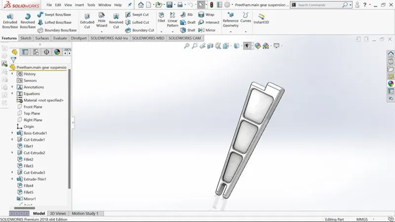
Main Gear Assembly
- Create an assembly file
- Go to reference and create axis by selecting the two planes (top and right plane)
- Rename the axis as the main gear axis
- Create a new plane by taking the right plane and adding an offset distance of 2690mm
- Insert reference geometry and add a new axis by selecting the two planes (top plane and the new plane)
- Rename as suspension arm axis
- Insert the component and import the main gear base and click on ok
- Click on mate select the front plane of the main gear base and the front plane of the assembly and click on ok
- Click on mate, concentric, and select the main gear axis and the cylindrical face of the part
- Go to insert and import the wheel plane the wheel on the right-hand side
- Add a concentric mate between the wheel and the landing gear
- Add a concentric mate between the 3rd portion of the wheel and the inside portion of the wheel hub
- Create a liner pattern select the face and use a distance of 1500 and no of instances of 2 and make sure to select the wheel and reverse the direction and click on ok
- Create a mirror using the right plane from the main gear base as the reference plane and select the option to mirror the wheels
- Insert another component and import the main gear suspension arm (1)
- Add a concentric mate on the circular reference of the bottom face and the landing gear
- Add a coincident mate on the front plane of the main gear base and the right plane of the suspension arm
- Insert another component and import the main gear suspension arm (2)
- Add a concentric mate on the circular reference of the top face and the landing gear
- Add a coincident mate on the right plane of the main gear suspension arm (1) and the right plane of the main gear suspension arm (2)
- Use the concentric mate option of the main gear suspension arm (2) and the suspension arm axis
- Try a quick test and check for the movement of the arm
- Apply mate and go to advance mate and a min and max value
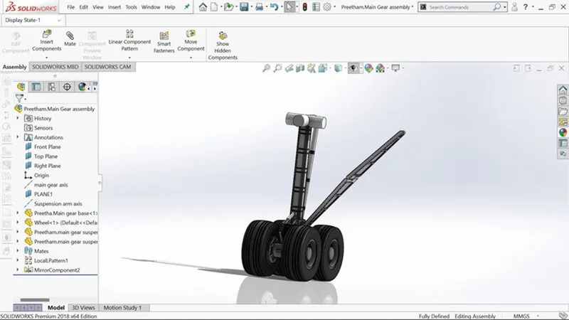
- Engine
The power component of an aircraft propulsion system is the aircraft engine, sometimes known as an aero engine. The majority of aircraft engines are piston or gas turbine engines, while a handful has been rocket-powered, and several tiny UAVs have employed electric motors in recent years.
- Create a new part and insert the sketch picture and select the engine blueprint
- Select full image and give transparency of .4
- Name the sketch as engine blueprint
- Next sketch on the right plane, spline form the origin vertically towards the top edge of the engine
- Next line from the origin towards the back and upwards, apply dimensions on the spline handles
- Revolve boss base and select the horizontal line as the axis of rotation
- Create a new sketch on the front face of the body with a circle dia of 2500mm
- Create an extrude cut off 1800
- Create a split line on the right plane using the line tool
- Go to features split, cut the part, and make sure to consume the first piece of the engine
- Apply white paint on the body
- Apply a fillet of 100m and click on the outer edge
- On the inner edge, we apply a fillet of 70mm
- Add the appearance to all leading edges of the cowl apply chrome plate appearance
- Insert shell on the front and back face of the body of 10mm
- Create a sketch on the right plane draw a sketch line parallel to the split line and make sure the endpoints of the line touch the edges of the cowl
- Create a split using the split line feature
- Paste the same appearance on the split as of the leading edge of the cowl
- Create a new sketch on the right plane using the line tool
- Create a triangle of proper dimension at the midpoint of the line
- Apply the extrude cut throughout and click on ok
- Apply fillet on the inside edge of 120mm and the second fillet of 30mm on the outside edge of the extruded cut
- Create an axis on the front and the top plane
- Once the axis is done go for circular pattern create a 13 instance and the feature will be the extruded cut and the fillet and click on ok
- Apply additional fillets on the outside edges of the extruded cut and keep the tangent propagation on
- Select the right and begin the next sketch from the origin using spline and line tools and give proper weight sin the spline handle
- Use revolve boss extrude and select the horizontal line uncheck merge result and accept
- Apply fillet to the back of the body of 10mm
- Apply an appearance of polished silver
- Create a new sketch on the front plane cantered on the origin with a dia of 1200mm
- Use split from the correct sketch to the last created body
- Add a painted car black to the front face of the inner body
- Create a new sketch on the top plane using a line tool and place it using the origin as a reference for dimension
- Create a new plane using the top plane as a reference with an offset of 1300mm towards the top
- Create a new sketch on the new plane using the line tool
- Use lofted surface and select the 2 sketches and click on ok
- Create a section view on the right plane
- Select the right plane and sketch, convert entities of the leading edge of the fan blade,
- Using the trim surface option click on the surfaces to trim
- Thicken the surface in bi-direction of 10mm
- Go to features and crate a champer of distance to distance with a value of 120mm to 20mm
- Create fillet of 10mmon the front edge of the champers
- Create a new sketch on the origin and the dia is 2580mm
- Go to insert and split tool, cut only the fin, and select the bodies to consume
- Apply s circular pattern on 18 instances and the bodies will be the fin
- Start a sketch on the right plane using a spline option
- Apply a Surface revolve feature, using the horizontal axis as the reference plane
- Thicken the surface body bi-direction of 10mm
- Select the right plane, Create a triangle of proper dimension at the midpoint of the line
- Apply the extrude cut throughout and click on ok
- Apply a fillet of 84mm to the inside edge and outer edges of 24mm
- Once the axis is done go for circular pattern create a 10 instance and the feature will be the extruded cut and the fillet and click on ok
- Apply additional fillets on the outside edges of the extruded cut and keep the tangent propagation on
- Sketch the right plane using the line and spline option
- Create a boss revolve using the horizontal line as the axis of rotation, uncheck merge result
- Sketch the right plane using the line and spline option as shown
- Apply boss extrude at a midplane uncheck merge result with the value of 630mm
- Add a manual draft value with an angle of 1.7 deg and the neutral value will be the front face
- Create another sketch on the right plane select the outside edge and convert as entities and sketch some lines and splines with proper dimension
- Create a revolve cut using the horizontal line as the axis of rotation
- Apply a fillet of 1000mm select the curved edges and click on ok
- Combine the two bodies using the combine option and add fillets of 200mm between the 2 bodies
- Apply variable fillet by selecting the 2 edges add a radius of 320mm and at the rare is 5mm
- Repeat the same command on the other side as well
- Apply appearance as required
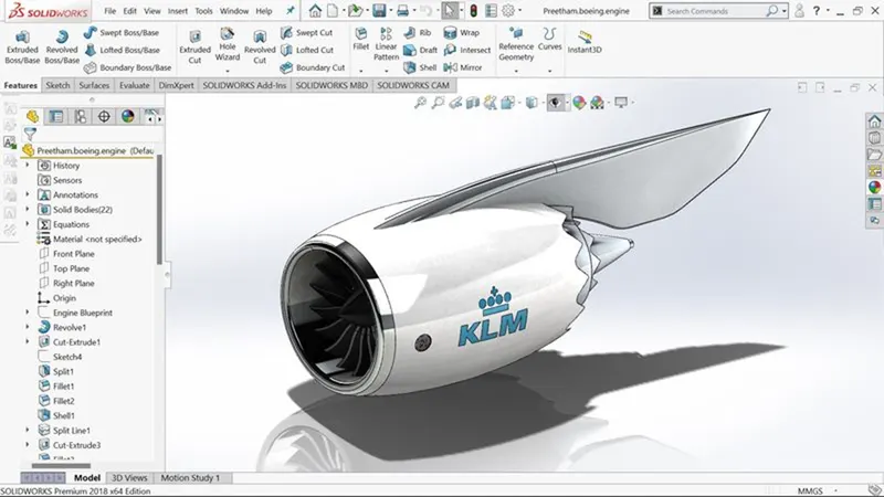
- Livery
An aircraft livery is a collection of color, visual, and typographic identifiers applied to aircraft by their operators (airlines, governments, air forces, and occasionally individual and corporate owners).
- Change the appearance of the overall design of the body to a painted car to white color
- Create a new sketch on the right plane between the upper and lower windows along the horizontal direction using the line, spline, and 3 point tangent tools. Using the origin as the reference point for the dimension
- Offset the above sketch of a distance of 200mm
- Insert > curve and split line select the two faces of the body for the projection of the split line
- Select all other features such as doors where the projection has to reflect
- Insert a block using the right plane and select the right livery block and place it over the right side of the body using the point and origin as the reference
- Insert the split line and select all the faces where the livery will be projected and select a single direction (on the right side)
- follow the same procedure on the left side for the projection of livery on the left side of the body
- select the nose face and apply the appearance of blue high gloss plastic, also select the upper part of the livery to apply the same appearance including the doors and the letters
- select a different appearance for the small face beneath the first appearance that runs throughout the body select high gloss color and change the RGB value to a darker shade select all the faces including the doors and letter that the face runs through
- open the engine solid part model
- select the right plane and insert the block and browse for KLM engine left and place it on the origin
- select insert >curve > split line and select the left side of the engine housing and click on a single direction
- follow the same procedure on the left side of the engine housing
- apply appearance on the liveries of blue high gloss plastic and finish
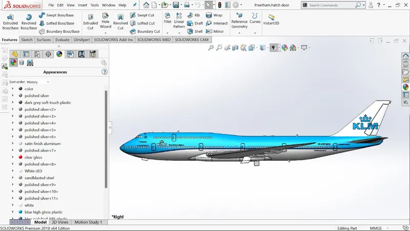
Assembly
- File newly create a new assembly
- Import the boe747 file and click on ok which will be placed at the origin by default
- Insert the next component of the engine and place it nearly to the right position and then select a mate and coincident to the right plane and engine right plane
- Modify the distance value of 21100mm, manually drag the component to the position mate coincident with the top plane of the assembly and the top plane of the engine and enter a distance value of 2000mm
- Select the front plane of the engine and assembly and give a distance of 35800 and click on OK
- Insert the engine component again and mate the engine using the same procedure as above but modifying the distance as per the placement of the engine
- Create a linear pattern and select the direction as the axis that is going left to right select the no of instances as 2 and increase the distance value of 24000mm and select on ok,
- Follow the same procedure as above and place the other engine with a distance of 42000mm
- Insert a new component nose gear assembly, add a concentric mate between the nose gear axis and the cylindrical body
- Apply Coincident mate Right plane of the nose gear assembly and the assembly
- Insert a new component main gear assembly and place it near the rear
- Apply concentric mate between the cylindrical face of the main gear assembly and the main gear
- Apply a coincident mate of the front plane of the assembly and the front plane of the main gear assembly
- Apply parallel mate between the right plane of the assembly and the right plane of the main gear assembly
- Apply mid flexible sub-assembly option and note that we can move the main gear axis
- Go to mate option, mechanical option, and select gear, grab the cylindrical face rotate around and the select the cylindrical face,
- The same procedure is followed to insert another main gear assembly component
- Mirror the main gear assembly components by selecting the right plane as the mirroring plane, click on next and select the synchronize movement of flexible subassembly components and click on ok
Front view
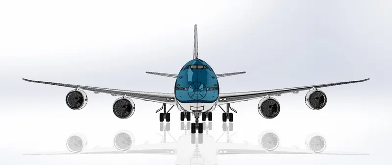
Back view
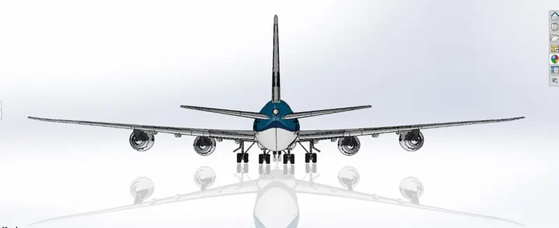
Side View
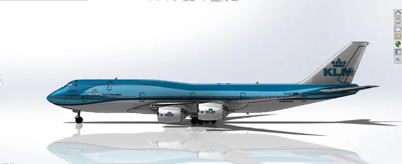
Top View
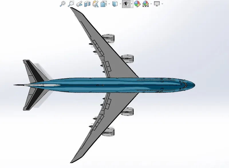
Bottom View
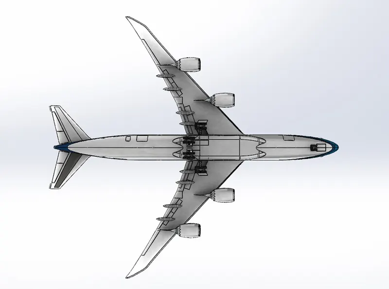
Isometric View
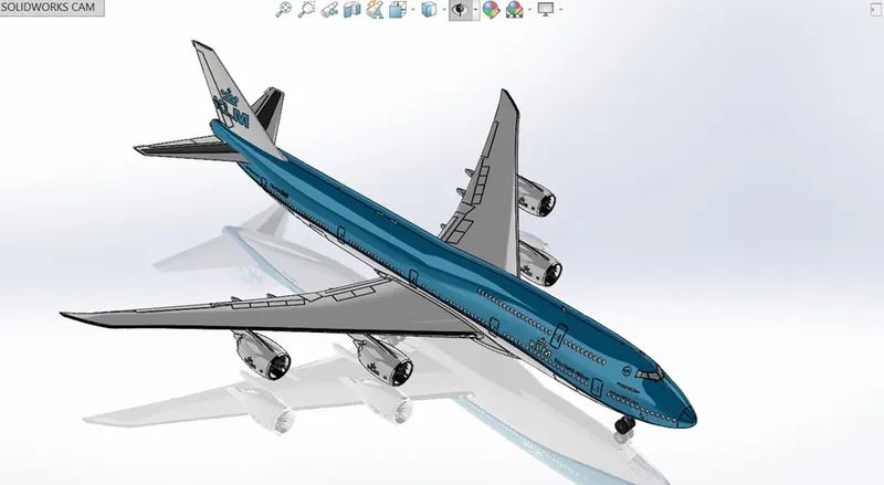
Rendering:
A rendering is an artistic drawing of what a new structure would look like, and it comes from the graphic design field. A rendering is a specific view of a realistic image in Computer-Aided Design (CAD). We obtain a concept of how the Boeing 747 would look in the landscape by rendering it. SOLIDWORKS Visualize was used to create this rendering. We may add numerous camera views to the model using PHOTO VIEW 360, and we can configure various angles, directions, and appropriate distances to acquire the optimal camera view. We modify the color of Boeing 747 pieces, backdrop pictures, brightness, rotation, and other helicopter settings during rendering. We can gain more detailed visuals of the scene by increasing the resolution and changing the number of passes.