Project 1
Statement of assignment:
Route the Wiring harness on the Given Engine and Prepare to flatten the view drawing in CATIA V5. Application of all Packaging rules, Industry best practices studied in this course shall be demonstrated in design. Apply Protection coverings as required.
Available connector 3D data can be used, or you can download the connectors from www.te.com
Prepare & Submit all necessary reports like clearance, Clipping/Clamping selection, Harness fixing requirements, Harness continuity, and Assumptions if any along with CATIA 3D data.
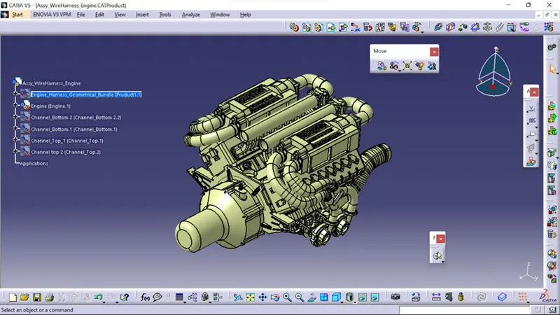
- The figure above depicts an engine with 8 cylinders on the right side and 8 cylinders on the left side.
- There are 16 injectors in total, with 8 injectors used for 8 cylinders on the right side and 8 injectors used for another 8 cylinders on the left side.
- There are also four camshaft sensors, one engine oil pressure sensor, one engine oil level sensor, and one crankshaft sensor, for a total of 23 sensors that must be electrically connected.
- 4-pole connectors are commonly used for engine fuel injectors.
- The engine will also include an interconnection connector that will connect it to other parts of the vehicle. As an interconnection connector, we will use a 12-pole electrical connector with an Anti-rotational mounting clip.
- A plastic guiding channel will be used to refer to the Harness Where the Fuel injectors the channels used will be made of a material that can withstand temperatures of at least 150° C.
- The bend ratio should be 1.4 for all bundle segments.
Step 1: Creating Context Assembly
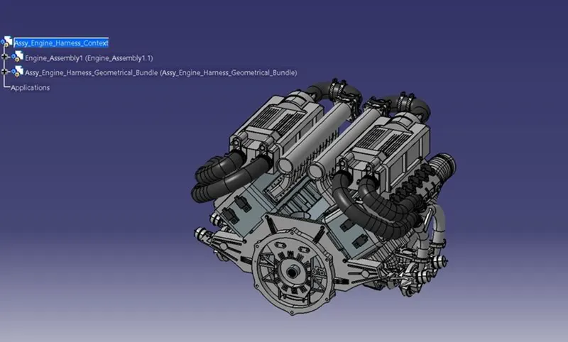
- A Context Assembly for Engine Harness has been created, which will work as the main assembly as shown in the figure above.
- A Context Assembly will contain Engine Assembly data of the Engine and Engine Harness Geometrical Bundle Assembly.
Step 2: To define the Connectors
Here, according to the requirement, we are using
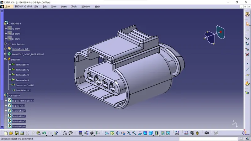
- 'C-1563689' which is a 4-pole connector for injectors and Oil Sensors
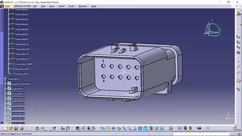
- ‘C-776438’ Which is a 12 Pole connector is used as an inline Connector
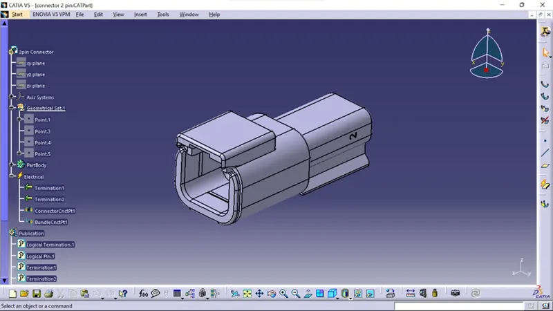
- And a 2-pole connector is used for Crankshaft Sensor
This CAD data was obtained from te.com. To electrically define a connector, we must first define the geometrical parameters such as the bundle connection point and connector connection point in the Electrical Part Design workbench for the downloaded connector.
'C-1563689'
‘C-776438’
2-pole Connector
Step 3: Adding connectors to all Sensors and the mounting points
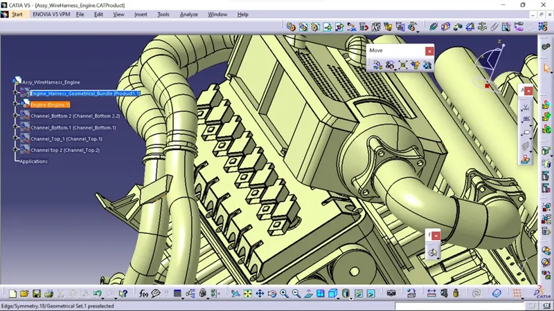
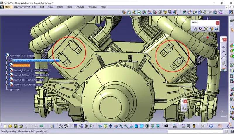
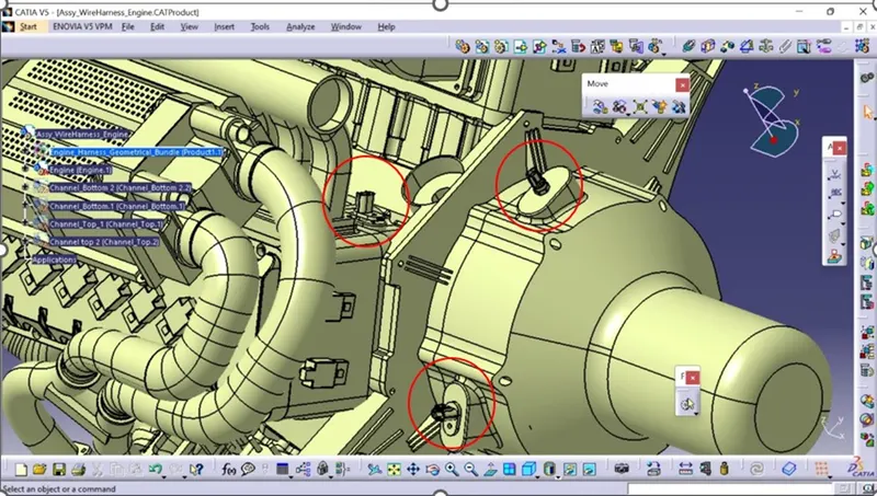
In this step, we will connect all of the injectors and Other Sensors, which will require a total of 23 connectors to be added to the Engine Harness Geometrical Bundle Assembly. To locate all 23 connectors at their desired locations, we must use manipulation tools as well as compass, snap, and smart move features.
Identifying all the injectors and Sensors.
- Injectors
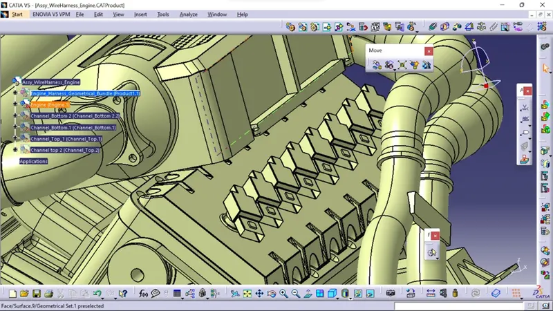
- Cam Shaft Sensors
- Oil and Crankshaft Sensors
Positioning all the Connectors to its Position Along with Bundle Supports
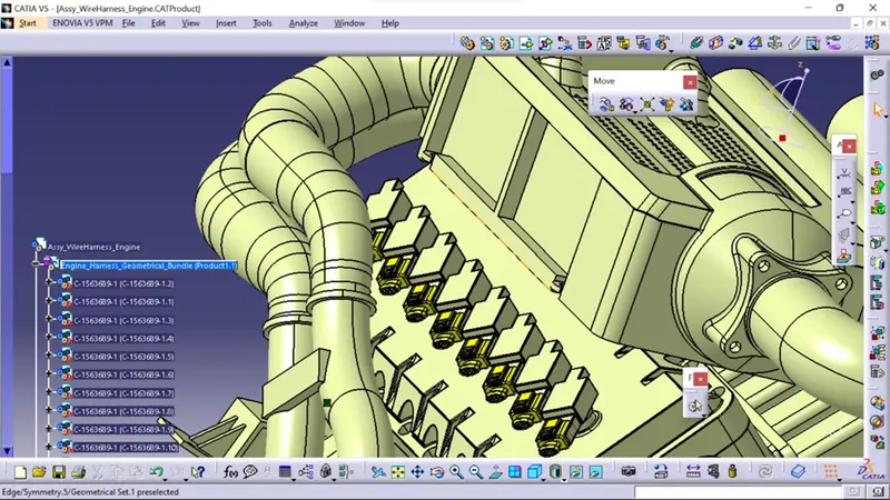
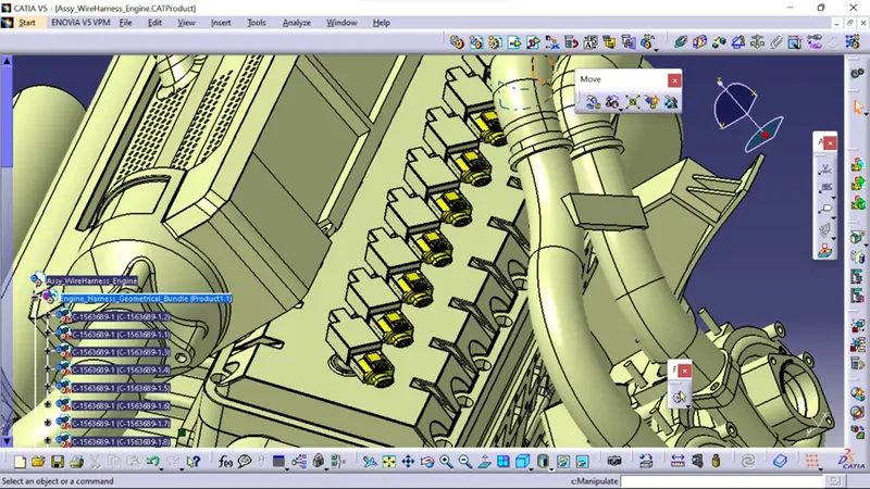
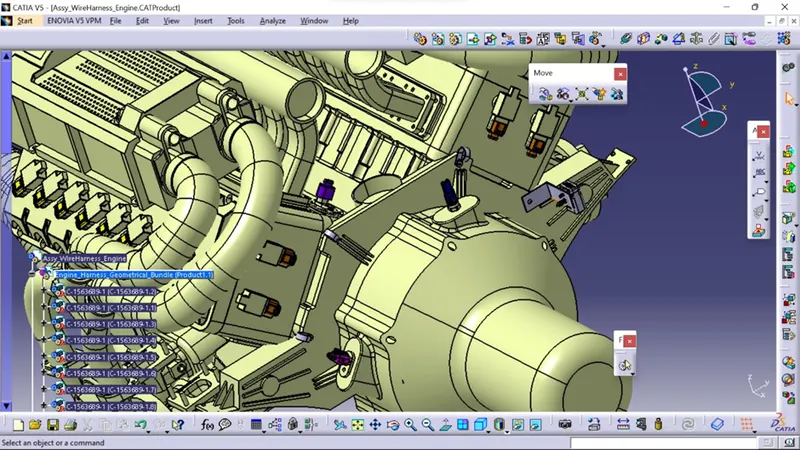
For Support, we use Pclamps and L clamps with Anti rotational Fir tree Clip
Inline Connector supported with L clamp and Fir tree clip.
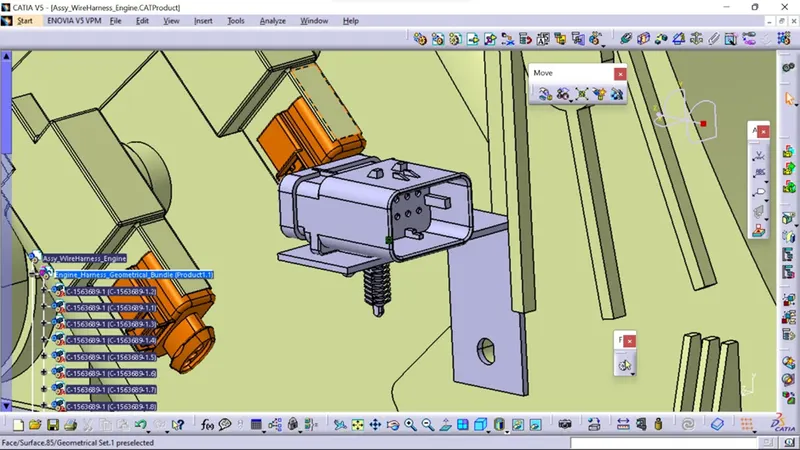
To provide mounting for the interconnection connector, we must add a sheet metal bracket. Also, the bracket must be placed inside the context assembly and outside of the engine and geometrical bundle assemblies. The bracket should be attached to the existing bolt in the manner shown below. This bracket should have a clockwise locking system so that it cannot be moved freely. The locking feature for the bracket is performed by the rib. All design ideas should be discussed with the engine designing team so that there is no disruption to the engine's smooth
P-Clamps
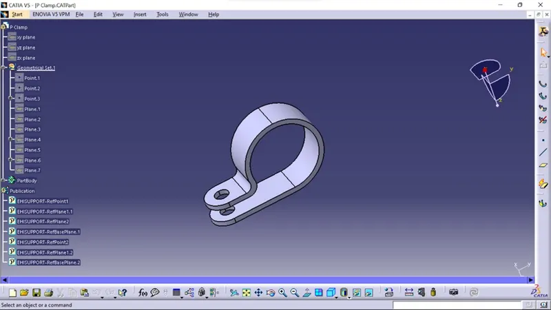
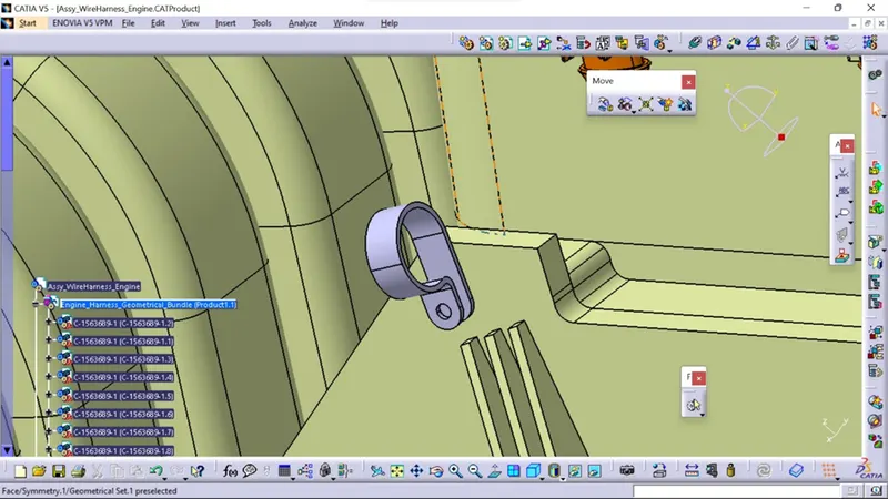
- We need to mount three P-clamps on the engine's existing bolts, so we must first define the P-clamp electrically with geometrical parameters, entry, and exit points on both the left and right sides of the P-clamp, as shown in the figure below.
Step 4: Mounting of a plastic guiding channel
Because the engine has 8 injectors on the right side and 8 injectors on the left side, which are very close to each other, we must now add a plastic guiding channel. As a result, plastic guiding channels are the best option for proper and easy wiring harness routing. It will simplify the complicated wiring harness routing. We'll need two different guiding channels for the engine's right and left sides. Now, before we place the guiding channel, we must define its geometrical parameters, as shown below.
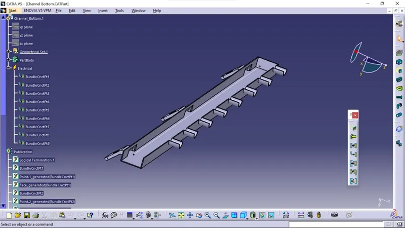
- At a 550mm distance, we must create point 1 at the entry face and another point at the endpoint.
- Now connect both points to form a line that will be used to route the wire harness bundle inside the guiding channel later.
- The process will be repeated for the right side guiding channel and the left side guiding channel.
- We created bundle entry points for the eight connectors, one at the channel entry face, and electrically defined the guiding channel as equipment.
- We have located the guiding channel at the desired location after electrically defining it.
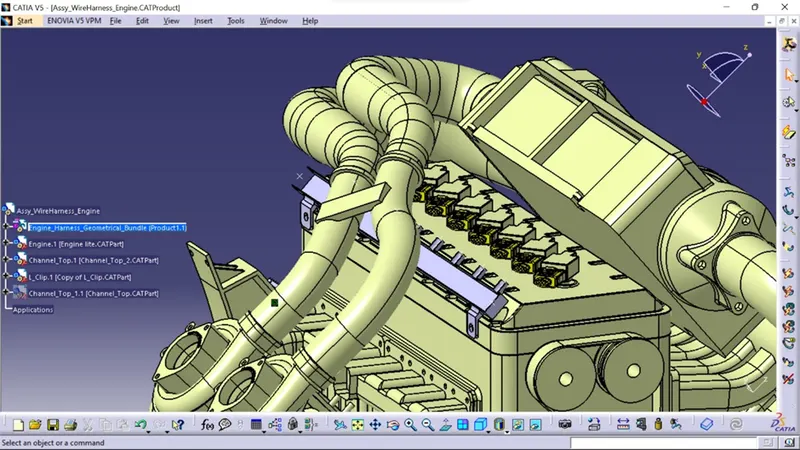
- For the placement of the guiding channel, we used various commands such as manipulation, snap, smart move, compass, and so on.
- At this point, we have only reached the bottom of the guiding channel.
- The entire assembly is ready for routing
- Mounted are all 23 connectors, 3 P-clamps, 1 Interconnection connector, and 2 plastic guiding channels.
Step 5: Bundle routing from Interconnection connector to 3 P-clamps and to 4 Camshaft sensors
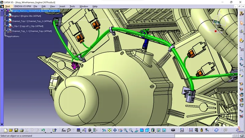
- The bundle segment is routed from the interconnection connector to three P-clamps in this example. Two branches are added from the created branch point to cam-shaft sensors while maintaining the Bend radius ratio of 1.4.
Step 6: Routing to the plastic guiding channel and adding Branch Points to the bundle segment inside the Channel
Another branch point is added from the interconnection connector. From this branch point, the bundle is routed to the right guiding channel.
- The bundle segment within the guiding channel is created by using the pre-made sketch as the routing definition.
- The bundle segment has been routed from the newly created branch points to the 8 fuel-injector connectors. The diameter of the bundle is assumed to be 5mm.
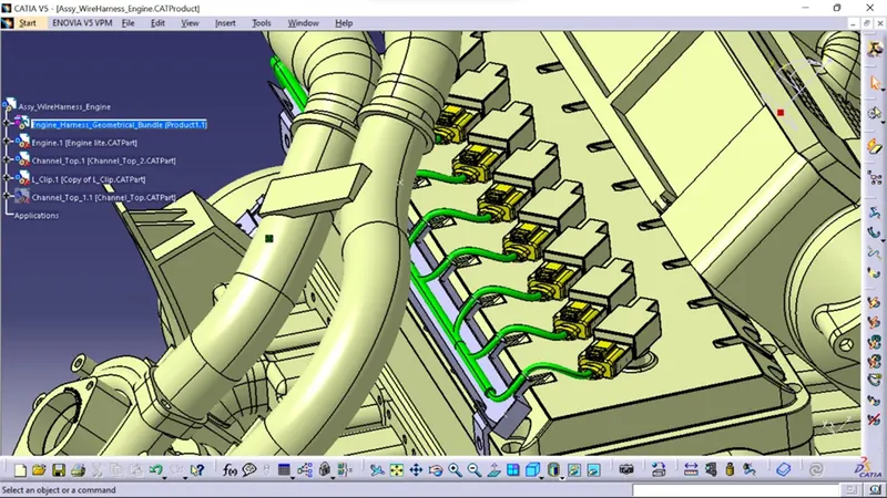
- Similarly, we have done routing for the left side guiding channel
Step 7: Adding protective coverings and guiding channels top shell to harness bundle
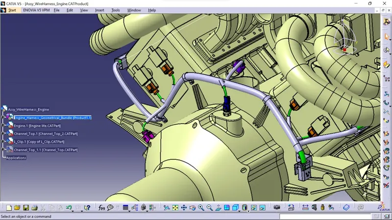
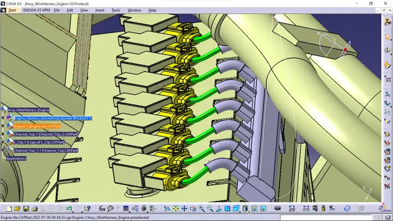
Here in below figure, we have done with whole wiring harness routing for the Engine. Now, we have to add protective coverings to all bundle segments and top shell of the guiding channel.
Step 8: Checking bundle continuity
Step 9: Creating flatten view of the engine harness geometrical bundle assembly
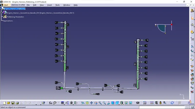
- The bundle assembly was extracted into an Engine Harness Flattening Product file, which was then flattened along the face of the interconnection connector.
- We developed a flattened view.
- we must rotate bundle segments connecting to the four cam-shaft connectors using the 'Rotate' feature of the flattening workbench.
- It should be noted that the 'face' of the interconnection connector serves as the flattening plane, so we must rotate the bundle segments only along that plane.
- We used various features such as bend, rotate, and roll to streamline the harness for better representation.
The flattened view's final representation
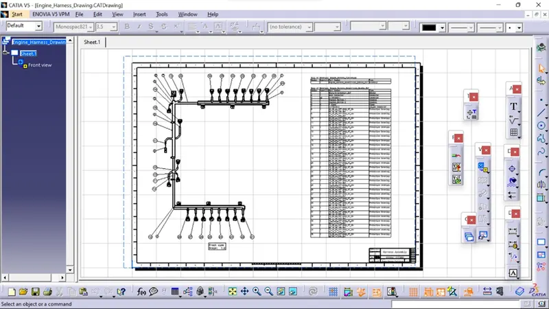
Step 10: Creating a flattened view drawing for the wiring harness assembly
In the figure above, we're creating a new drawing file and defining all of the required drawing parameters. The front view of the Engine Harness Flattening Product file must be inserted into the Drawing file. As shown in the preceding figure, we must define drawing properties. It should be noted that the 3D wireframe is always ON in the 'Dress up' settings. If this option is not enabled, the bundle segments will not be visible in the drawing view. the Engine Harness Flattens view's final Drawing view