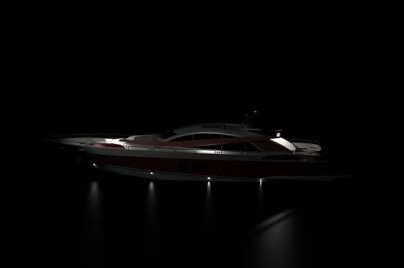
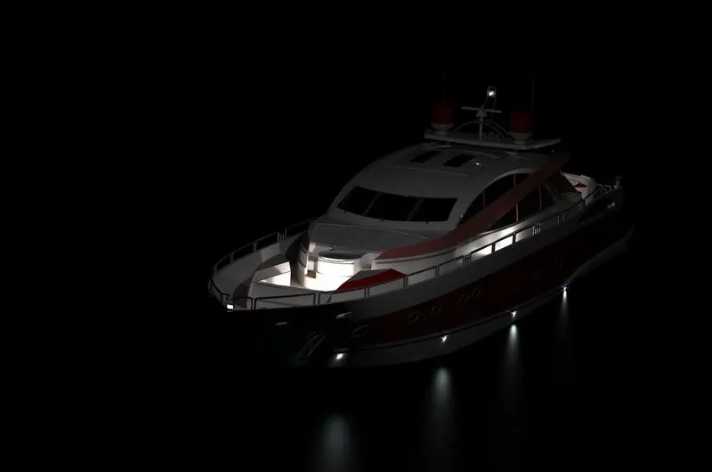
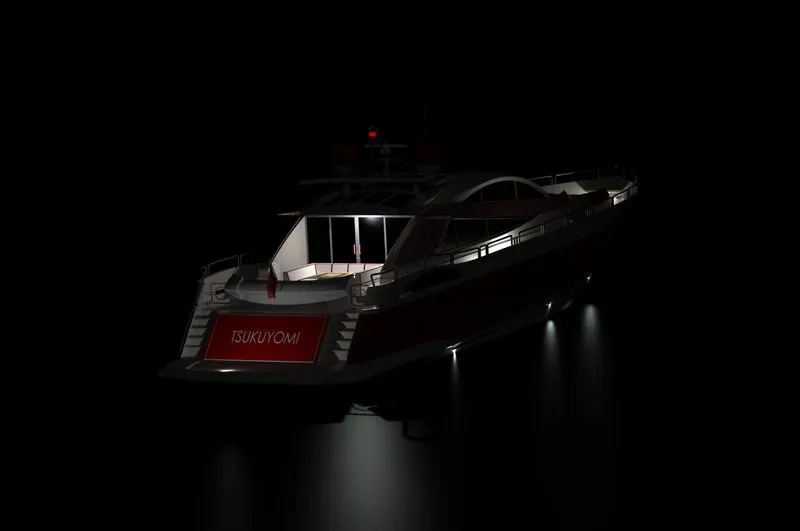
Modelling and Rendering a Photo realistic image of Sunseeker Predator Yacht
INTRODUCTION
Through this project, we will learn how to design a Sunseeker Predator Yacht assembly using SOLIDWORKS. First, we will learn how to use the software, then we will draw parts using blueprint sketches, where we can learn the dimensions of the parts, Once the Yacht parts have been designed, we assemble the yacht. We then add decals, lights, and cameras, and render the yacht using SOLIDWORK photo view 360.
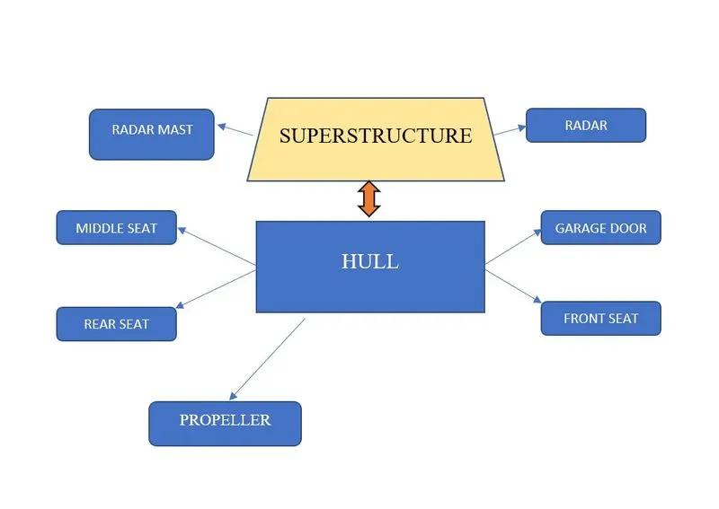
The Components that we learned and designed in a Chopper are:
- Radar.
- Propeller.
- Hull.
- Garage Door.
- Front seat.
- Middle seat.
- Rear seat.
- Superstructure.
- Radar mast.
OBJECTIVE
- To learn the basic commands of SOLIDWORK.
- With the help of a blueprint sketch, we design all the parts of the chopper.
- Assembling all the parts in SOLIDWORK.
- Get the knowledge of concepts like decals, light, and camera angle.
- Proper setting of image quality and getting realistic view with the help of photo view 360.
DESIGN APPROACH:
As part of the design process, there are two types of approaches.1. Bottom-up approach and 2. Top-down approach. Here, we have used the bottom-up approach, and we get a clear picture by defining these terms.
- Bottom-up Approach: In this design approach, the most primary operations are specified first, then they are combined later to make larger progressive units.
- Top-Down Approach: This approach is an Assembly-centric modeling method in which an assembly design is done at the highest level possible, and individual parts and subassemblies are defined within the context of the overall assembly.
To design different parts, we used the following features and Properties:
- Extrude boss
- Fillet
- Revolve boss feature
- Extrude cut
- Shell
- Linear pattern
- Mirror
- Reference geometry
- Projected curve
- Knit
- Mate
Extruded Boss:
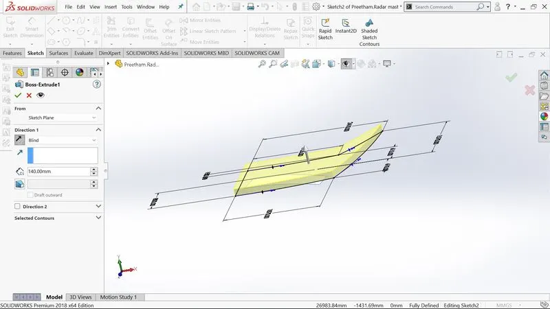
Extrude boss is the most basic feature of SOLIDWORKS. It requires a complete sketch to convert a 2D sketch into a solid body. After you exit a fully defined sketch you see the boss extrude option and a property manager window opens. Using the property manager, we can see from where the feature begins and ends that we need to add dimensions to it. It creates a completely solid body of any shape with closed entities. In this feature, we can add dimensions to both the direction (direction 1 and direction 2) and the size.
Fillet:
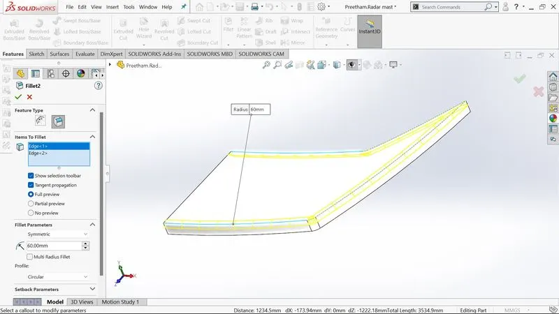
When a solid part is drawn, it will be having some sharp edges to give roundness to these edges we add fillets. It will make the sharp edges or corners a round shape having different sizes and radii. The material can be added or can be removed according to the conditions whether the edges are internal or external. fillets are used in solid bodies to hide corners and edges also giving a nice appearance to the part. Various types of fillets are used depending upon the part.
Revolve boss feature:
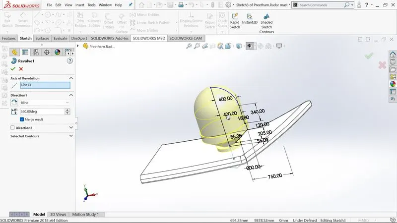
This feature works by selecting the axis of a sketch adding a round material by revolving around the selected axis. We can select an edge of a sketch if there is no axis.
Extrude cut:
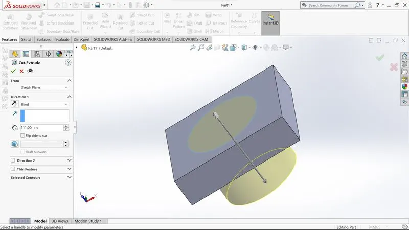
This feature allows you to remove unnecessary parts from the geometry or to give the desired shape to a sketch or solid part by sketching the solid part and then using this feature to get rid of that part.
Shell:
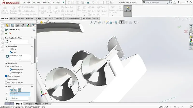
There is a very handy tool in SolidWorks that allows you to see what the inside geometry of a part will look like. In this tool, we add a thickness to the inside geometry and remove the material from the body so that the part appears hollow.
Linear pattern:
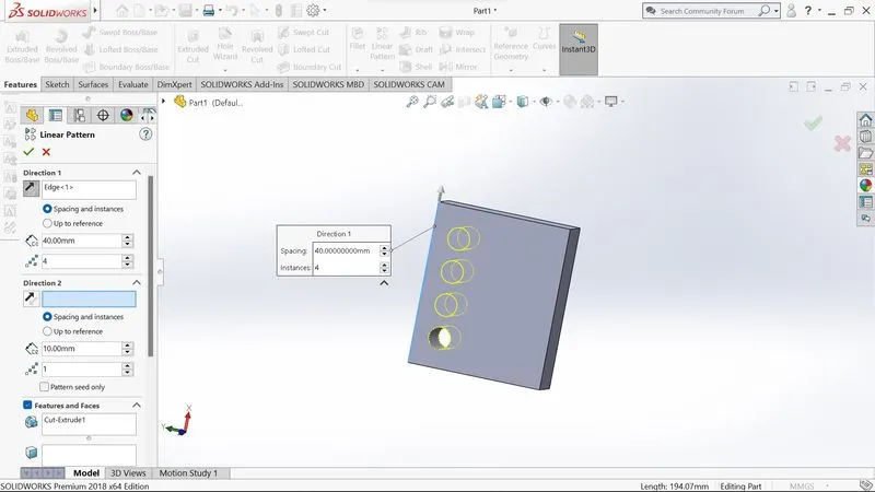
The linear pattern is a feature used to create a single sketch that can be used multiple times. The spacing, angles, and paths of this feature are given so that it can be used to draw or create a pattern This feature is spaced uniformly along one or two linear paths
Mirror:
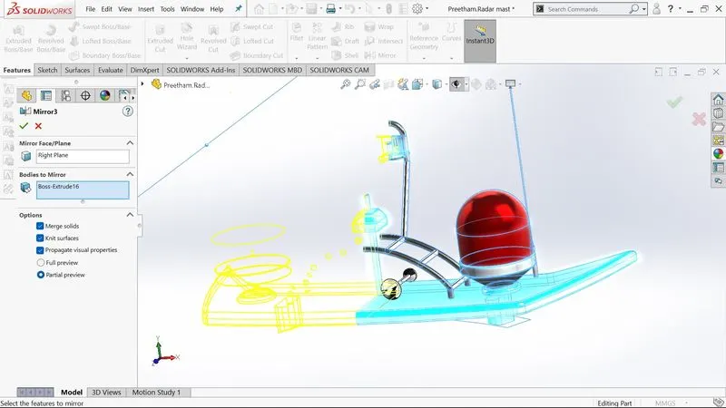
As this feature makes a copy of a solid part, it requires a plane or axis to mirror the part. Select the body to be mirrored, then choose an axis or plane, and then apply the feature. Multibody parts: Apply the feature to one or more multibody parts by selecting geometry patterns and using feature scope to select which bodies the feature should be applied to.
Reference Geometry:
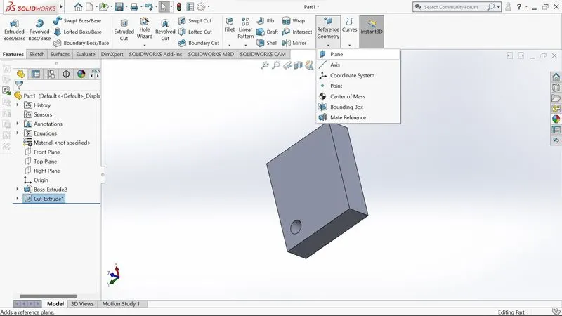
Surfaces and solids are defined by their shape or form. This includes planes, axes, coordinate systems, and points, which can be used in a sketch.
Use of Reference Geometry:
- Axis: If we want to pattern something and the axis is not available, then we can use the reference geometry axis to make it easier to do so.
- Plane: A reference geometry plane can be used to represent a plane when sketching and the sketch needs to be completed using a plane.
Projected Curve:
The curve can be projected by a sketch into a model to create a 3D curve We can create several closed or open contour projected curves from a single sketch Generally, the curve is the intersection of two extruding surfaces The curve which is created can be used as a path for the sketch of the part. Note: It does not create the curve of intersecting curves.
Knit:
Utilization of knit surface tools to combine two or more faces and surfaces into one. It creates a solid body when the knit surfaces form a closed volume or remain as surface bodies.
Mate:
Mates define a geometric relationship between assembly and component. When we add mates, they define the possible direction of linear or rotational motion for a component within its degree of freedom.
This feature includes:
- Coincident mate: Helps in making two planar faces to become coplanar which can be moved along one another but cannot be separated
- Concentric mate: Helps in making two circular faces concentric which can only be moved in the common axis
- Tangent: Helps in making a tangent mate between a face and plane
- Angular mate: Helps in making an angular relationship between a flat surface and the surface having some angle
Now let us see the above application of the features in the Yacht that we have built which is discussed part by part as shown in the flowchart.
Blueprint:
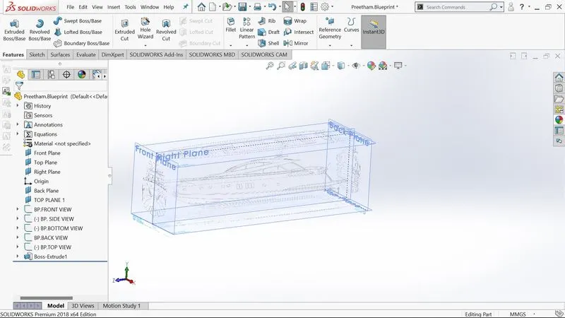
A blueprint is a two-dimensional series of drawings that shows how an architect envisions a project to look. Blueprints usually detail a structure's measurements, construction materials, and the precise positioning of all of its components.
When engineering designs were printed on blue paper with white lines in the mid-nineteenth century, the term "blueprint" was coined. Physical blueprints are seldom blue in the current building sector. Blueprints include construction drawings, construction plans, and working drawings.
We'll import all of the blueprints, including front, rear, side, bottom, and top views, and organize them on separate planes according to the appropriate measurements. We'll use these pictures as the foundation for building all of the yacht's elements.
Propeller:
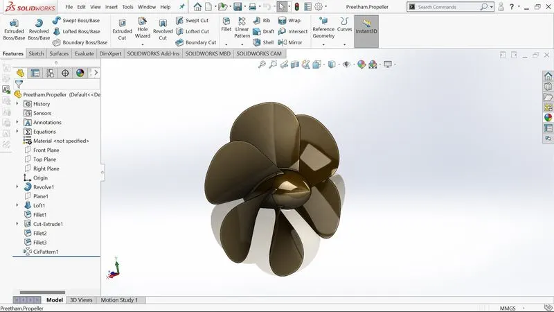
A propeller, sometimes known as an airscrew, is a device that transforms rotational motion from an engine or other power source into a whirling slipstream that propels the propeller forward or backward. The propeller is connected to the drive shaft of the power source either directly or through reduction gearing. A sketch was drawn on the plane that was later revolved to make a solid part, then using the Loft option and adding fillet on the corners, One of the blades was created, and it was afterward mirrored in a circular pattern with an instance of six to create a finished propeller.
Features used to create:
- Sketch
- Boss Revolve
- Solid Loft
- Fillet/Round
- Cut extrude
- Circular Pattern
Radar:
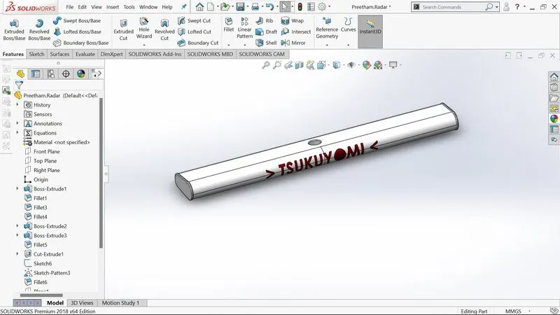
Radio Detection and Ranging System (RADAR) is an acronym for Radio Detection and Ranging System. It's essentially an electromagnetic method for detecting the position and distance of an item from the RADAR's location. It operates by emitting energy into space and measuring the objects' echo or reflected signal.
The drawing's side view is created, and a boss is extruded to the midplane, with a fillet on the edges for a smoother finish. The second half of the sketch is mirrored against the midplane, and a cut extrude is supplied to put the radar on the mast.
Features used to create:
- Sketch
- Boss extrudes
- Fillet
- Cut extrude
- Sketch Driven Pattern
- Mirror
- Text
- Split line
HULL:
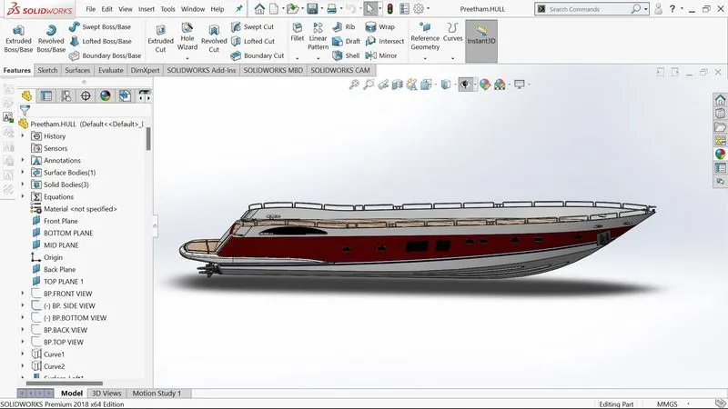
A yacht’s hull is a waterproof body. The hull may be open at the top (as in a dinghy), or it may be covered entirely or partially by a deck. It may be defined as the ship's watertight enclosure, which protects the cargo, machinery, and accommodation areas from the elements, floods, and structural damage.
The Hull was made using the following features with the reference from the blueprint designing the half of hull using surfaces and combining the other extrude features and mirroring the finished half design creating a finished Hull body of the Yacht
Features used to create:
- Sketch · Projected Curve · Loft · Surface Trim · Surface Extrude
- Fill Surface · Boss Extrude · Fillet · Extrude Cut · Linear Pattern
- Revolve · Dome · Sweep · Mirror · Combine
Garage Door:
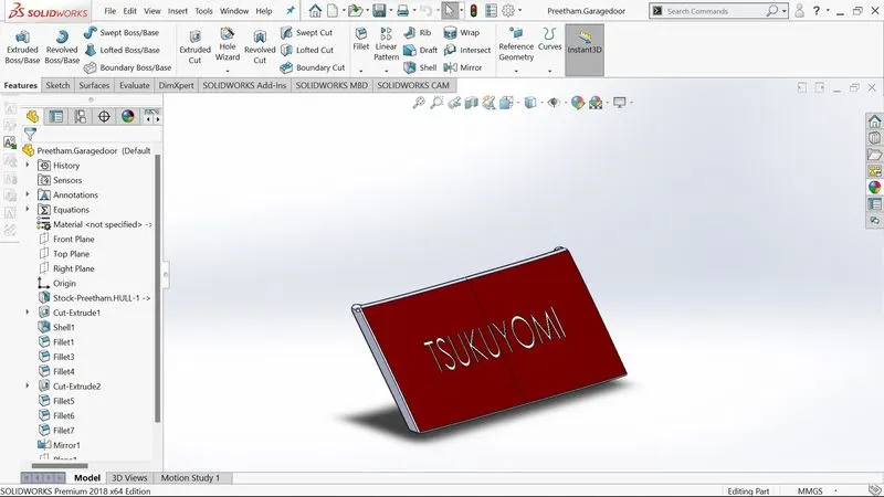
To create the garage door, we open the exported body of the hull as the main body sketch is made on the side of the body and extruded, and we put the shell feature on it by selecting three sides. The body is mirrored with the midplane to finish the garage door. Fillets are placed where there are sharp corners by extruding on the side top corner by creating a pivot point for the garage door to open and close
Features used to create:
- Extrude
- Shell
- Fillets
- Mirror
- Text
Front, Middle, and Rear Seats:
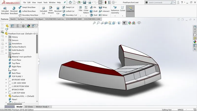
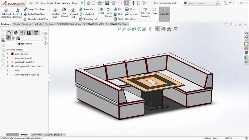
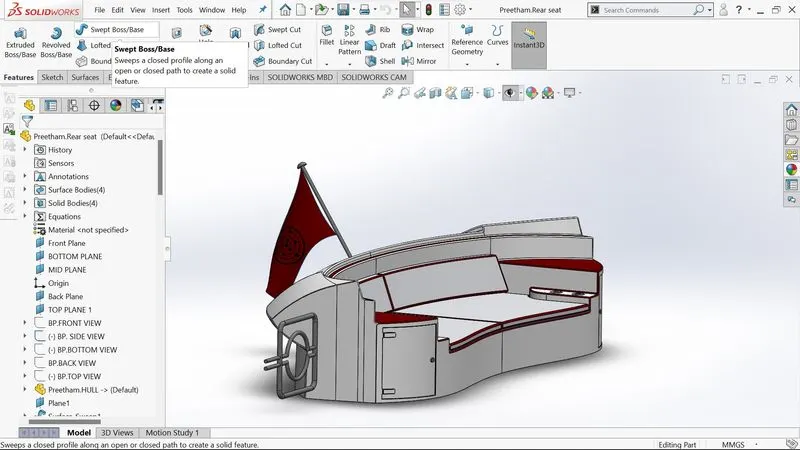
To make the Seats, we must first import the deck surface of the hull as an interface surface with the help of the blueprints sketch with arcs and lines, with the line being tangent to the arc. Then using the sweep, we create a fully enclosed surface design the unnecessary sections are trimmed of using the surface trim feature all these surfaces are later on knitted together all the sharp corners are filleted and later on mirrored while keeping the knit and merge option on creating on the whole body, Dome feature is put to provide a soft touch look where the seating arrangements are provided
Features used to create:
- Interface surface · sketch · sweep · Trim · Kint · Fillet
- Mirror · Dome
Front seat image:
Middle seat image :
Rear Seat Image:
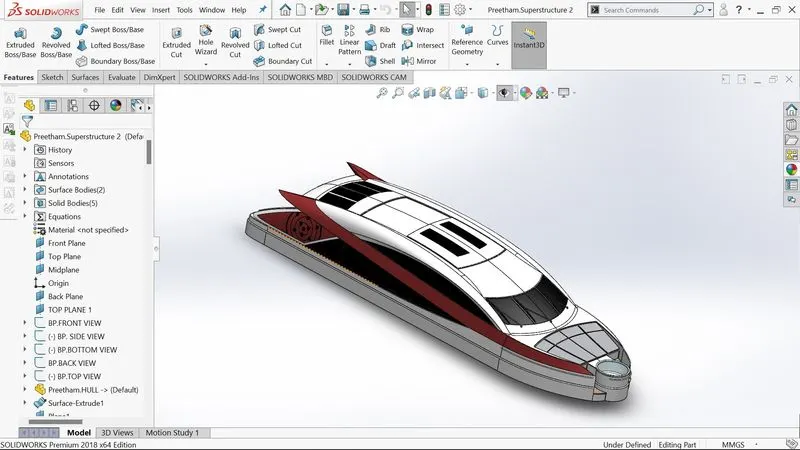
Superstructure:
The size of the superstructure has a significant impact on the Yacht's maneuverability. They're made in such a way that they bring value while obstructing speed and movement as little as possible. The majority of the superstructure is also designed fashionably. This is because it is the most immediately visible element of the ship, and it is also the ship's identifier, thus the designers aim to give it a distinct identity.
The modeling of the Superstructure begins with a reference to the blueprint of the Yacht. Surfaces, Projected lines, and creating a Solid body by knitting the surfaces are used, creating mirrors, and sweeping. Finally, a fillet was used to produce the entire portion, giving the Superstructure a pleasant appearance and rounding the harsh edges.
Features used to create:
- Sketch · Projected Curve · Loft · Surface Trim · Surface Extrude
- Fill Surface · Boss Extrude · Fillet · Extrude Cut · Linear Pattern
- Revolve · Dome · Sweep · Knitting · Mirror
Radar Mast:
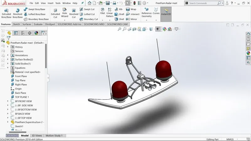
To make the Radar mast, we must first import the top surface of the superstructure as the interface structure, using it as the base with the help of the Blueprint 2D sketches are drawn and boss extruded, using revolve we make the radar amplifiers and mast will be made at the center fillet is provided to all the sharp corners, and using a mirror at the midplane the entire radar mast body will be created
Features used to create:
- Interface surface ·Sketch · Lines · Sketch fillet · Revolve ·Projected Curve ·Cut extrude · Offset · Revolve cut · Chamfer ·Fillet ·Mirror
Assembly of Yacht:
To assemble the parts, they were all modeled and imported. The Mate function is often used in assembly to locate and relate pieces to one another. The essential component is the chassis, which is inserted first and then fixed. The other components were inserted one by one, utilizing planes for reference and the mating feature to ensure that the part floats with the mainframe once it was fixed. During the assembling process, some parts were changed to make it perfect for the requirements.
Decals:
A decal is a type of "transfer" that consists of a printed picture, image, pattern, or design on a metal body. We've added decals to the Yacht’s Floor pattern on the Hull and stairs
Front View
Side view
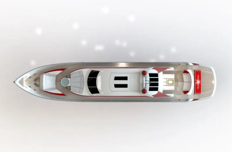
Top View
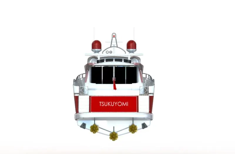
Back View
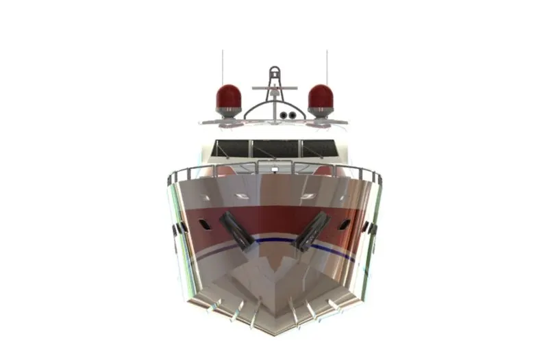
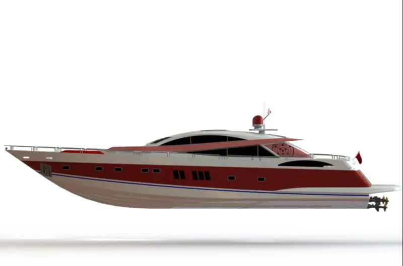
Rendering: A rendering is an artistic drawing of what a new structure would look like, and it comes from the graphic design field. A rendering is a specific view of a realistic image in Computer-Aided Design (CAD). We obtain a concept of how the chopper would look in the landscape by rendering it. SOLIDWORKS Visualize was used to create this rendering. We may add numerous camera views to the model using PHOTO VIEW 360, and we can configure various angles, directions, and appropriate distances to acquire the optimal camera view. We modify the color of chopper pieces, backdrop pictures, brightness, rotation, and other helicopter settings during rendering. We can gain more detailed visuals of the scene by increasing the resolution and changing the number of passes.