Fender Design - Wheel Arch Challenge
Introduction:
What is a Fender?
The part of an automobile, motorcycle or other vehicle body that frames a wheel well is referred to as a fender in American English (the fender underside). Its main function is to keep sand, mud, gravel, liquids, and other road spray from being flung into the air by rotating tires. Fenders are usually rigid and can be destroyed if they come into touch with the road.
As the tire rolls over the ground, sticky elements like mud can stick to the smooth outside tire surface, while smooth loose objects like stones can become momentarily embedded in the tread grooves. As the tire imparts kinetic energy to the attached objects, these materials can be expelled from the tire's surface at high speeds.
The top of a moving vehicle's tire rotates upward and forward, potentially throwing debris into the air onto other vehicles or pedestrians in front of the vehicle.
The fender is known as the wing in British English. (This could be referring to the front or back fenders.) However, rear fenders are sometimes referred to as quarter panels in current unibody vehicles.) In the United Kingdom, a mudguard is the equivalent component of a bicycle or motorcycle, or the "cycle wing" style of wing fitted to vintage cars, or overtires on lorries that are not integral with the bodywork, as it protects other road users – and, in the case of a bicycle or motorcycle, the rider – from mud and spray thrown by other road users.
Criteria to be considered while designing a Wheel arc as per the required standards
Engineers and designers must follow the stated design guidelines of the respective country while designing a vehicle's fenders, which protect both the vehicles and pedestrians from undesired particles such as dirt, water stones, and other debris. It also shields the car's body from mud and other debris thrown up by the tire as it runs. The automotive and road safety communities have recommended design guidelines. The standards for designing fenders in various nations are briefly mentioned in the images below.
US Standards
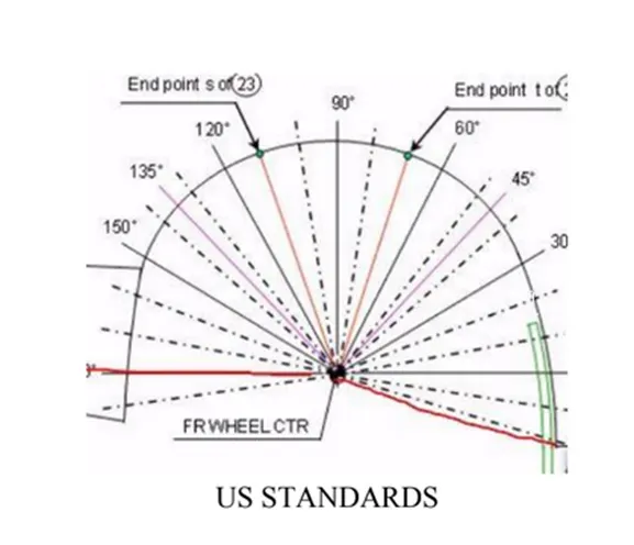
To comply with the regulations, all values must be more than 5mm.
Japanese standards
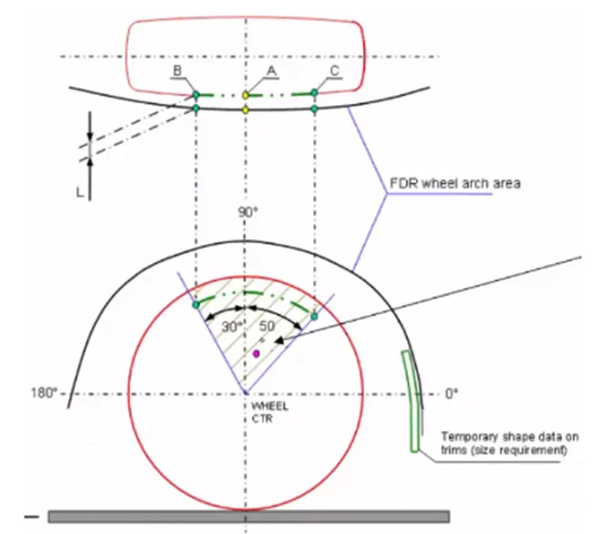
The minimum clearance required by Japanese standards is 5mm, and the plotting of points is essential as indicated in the diagram.
European standards
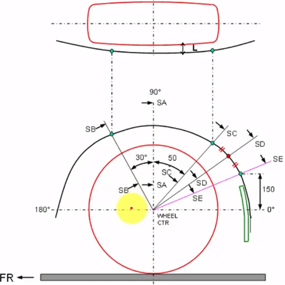
The minimum clearance made by all the points (SB, SA, SC, SD & SE) must be 10mm or more
I'm looking at a fender wheel arch that meets European specifications. The calculations will be done as shown in the diagram above; according to European standards, the minimum “L” distance is 10mm, and the fender provided by the supporting team is as shown below.
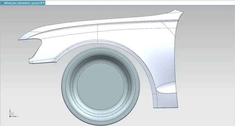
The following design will not be approved if it does not meet the minimum value as per the European standards and has to be modified.
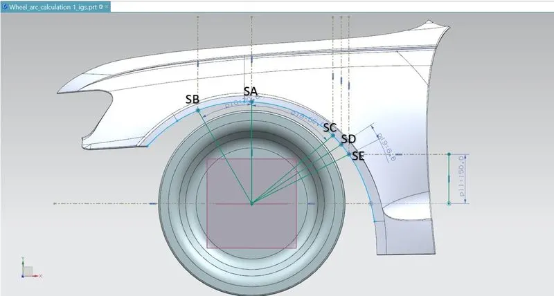
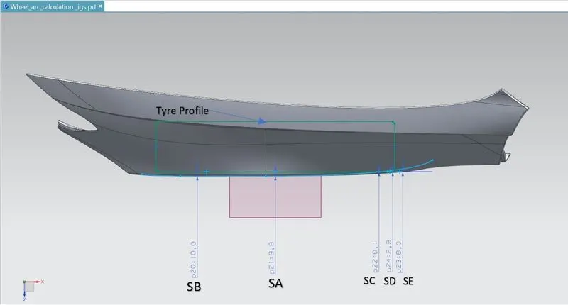
Points SA, SB, SC, SD, SE, were marked as per the European standards
Result of analysis
|
Section |
Required clearance |
Measured clearance |
Result (Pass/Fail) |
|
SA |
10mm |
9.9mm |
Pass |
|
SB |
10mm |
10mm |
Pass |
|
SC |
10mm |
0.1mm |
Fail |
|
SD |
10mm |
-2.9mm |
Fail |
|
SE |
10mm |
-6.0mm |
Fail |
Conclusion
After analyzing the design given by the support team, we can say that the design does not match the European standard as the clearance value on 3 ( SC, SD & SE) sections does not meet the minimum requirement, Where sections SA & SB meet the minimum requirement