Week 8 - Challenge 2 - Switch Bezel Design
Switch Bezel Design
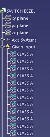
Given Surface
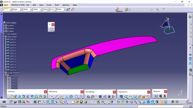
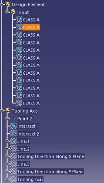
Tooling axis Creation
In injection molding, the Class A surface is first analyzed to determine the axis or tooling direction that separates the molds. Tooling direction is critical for plastic product design because it determines mold direction
Steps followed
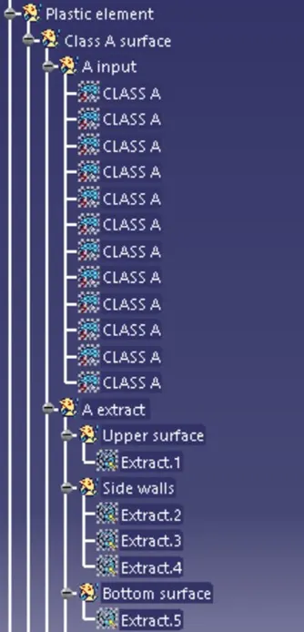
On the extracted surface, a reference point is first created.
To plot clearance lines, a new axis system is used.
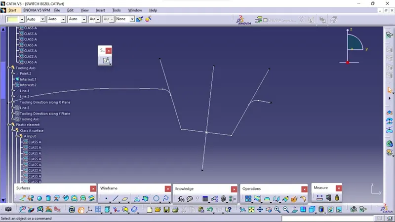
The x- and y-axes along with class A were used to develop the tooling axis using the Intersection curve
To form the Tooling axis, two clearing lines were bisected as shown below
The tooling axis's graphic properties are changed to identify the Tooling axis
On X Plane
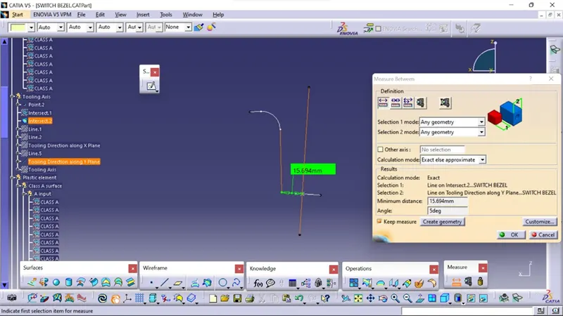
On Y Plane
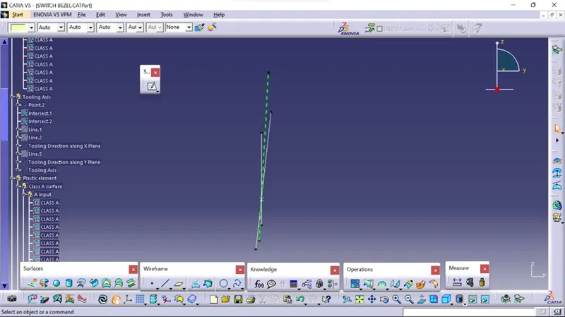
Bisecting with the two lines from the X and Y Plane we get an Ideal Tooling Axis
Creation of Class A surface
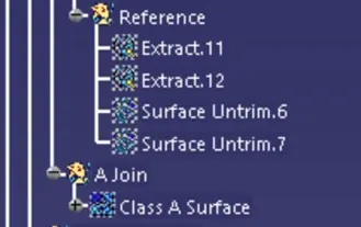
the given Surface is Joined together, using the Join command
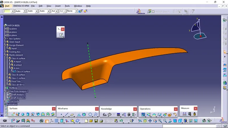
the Above Class A surface is later undergone draft analysis using the Draft analysis Comand
What is Draft Analysis?
Draft Analysis
For molded or cast parts, the draft angle is the amount of taper perpendicular to the parting line. It is measurable in degrees. Because plastic shrinks and sticks on molding surfaces as it cools, we draft the walls of the plastic part so that it ejects or breaks free from the molding surfaces more easily and without dragging. To reduce the risk of damage to the parts and ensure ejection, a functional injection molding part must have drafts on both the cavity and core sides.
Nominal values for Draft angles
- 3 Degrees is a nominal draft angle
- 5 Degrees can also be manufactured. Increasing the manufacturing cost
- 7 Degrees is considered for Textured surface parts
Importance of Draft in injection molding
- Reduces the possibility of part damage due to friction during the release
- Reduces mold wear and tear
- Ensures a uniform, smooth, unscratched finish
- Ensures the integrity and uniformity of other surface finishes and textures
- Reduces overall cooling time by reducing or eliminating the need for unusual ejection setups
Steps followed for Draft Analysis
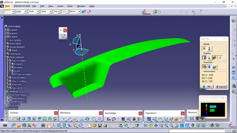
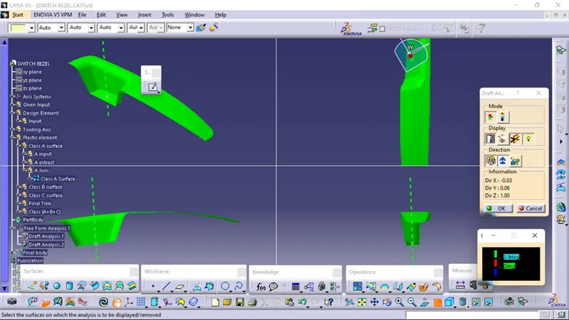
- The created part must be changed to the material mode in the display frame
- Compass is enabled and placed in the direction of the Tooling Axis
- The lock command is then used to fix the compass along the tooling axis
- Colour codes are classified and Draft angle is applied
- Running point analysis is used to display permissible draft angle
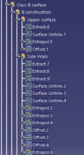
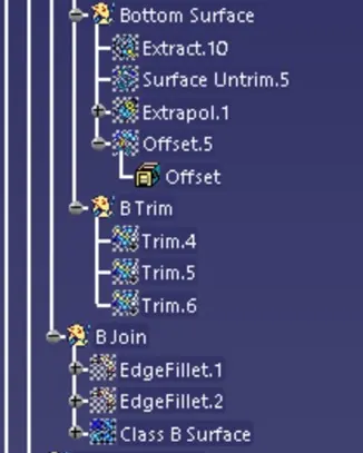
Creation of Class B Surface
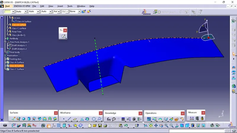
it is the offset surface of the Class A Surface the offset value depends on the thickness of the material, here the offset value is 2.5mm
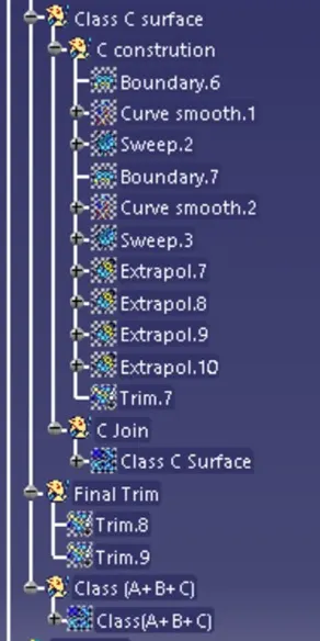
Class C surface
The surface that Joins both Class A and Class B surfaces is considered to be Class C Surface
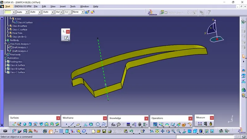
Class (A+B+C)
here we combine all the surfaces into one closed surface using the Trim tool Command
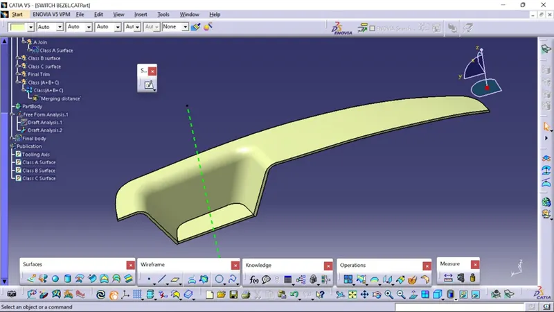
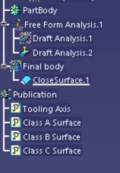
Conversion of Closed surface into Solid Part
using Solid Command we convert the closed surface to a solid surface in the Part model
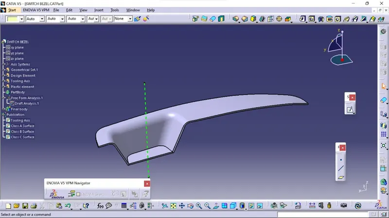
Iso View
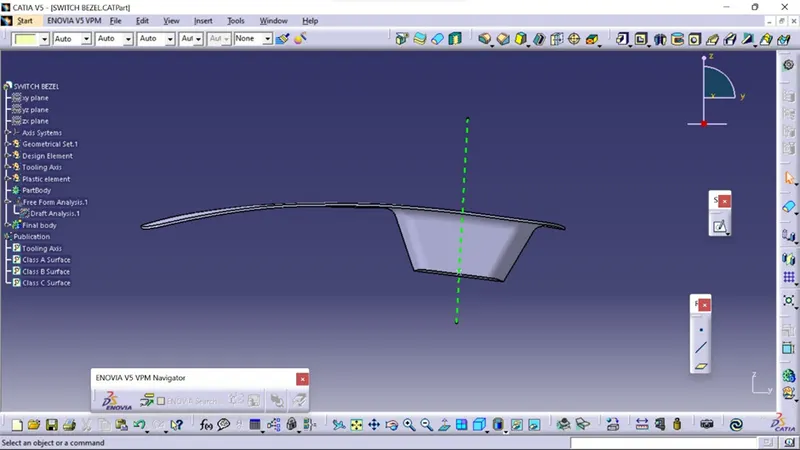
Side View
Top View
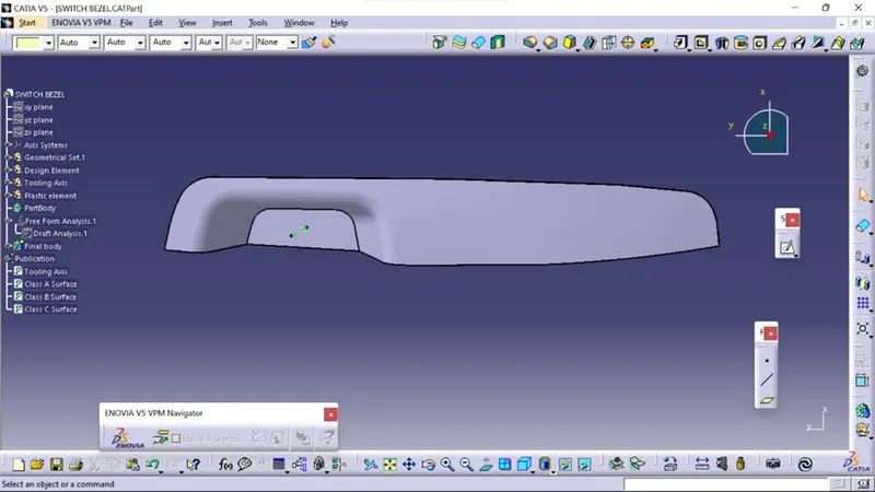
Front View
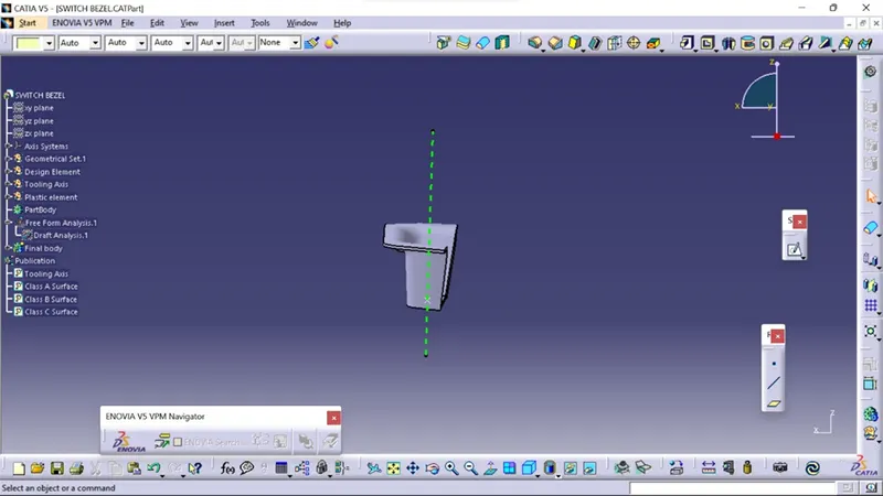
Tree View