Modelling of 25 storey building with the specified properties using ETABS
Aim:
To model and analyse a 25 storey building with the given specifications and to cross check the parameters as per IS1893 provisions.
Step-1:
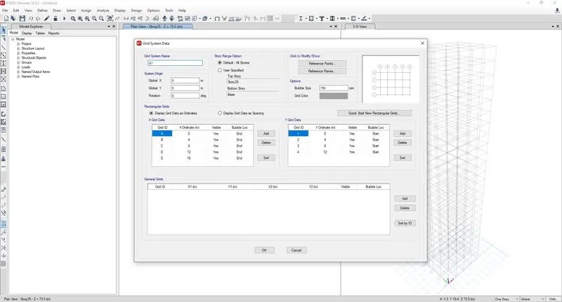
Edit > Edit stories and Grid system
Using the user defined grid input, The horizontal and vertical grid legends have been assigned with 4 meter bay on either sides
Step-2:
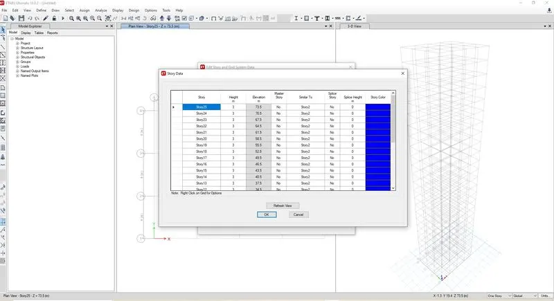
Edit > Edit stories and Grid system
Using the user defined storey input, 26 storeys have been incorporated (plinth at 1.5 meter height + 25 storey with 3 meter height each). Storey 1 has been labelled as master storey and all above levels are labelled similar to that.
Step-3:
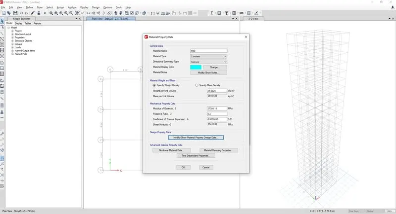
Define > Material properties
Using the material assignments, Concrete grade M30 is included in the material list. The default properties have been checked.
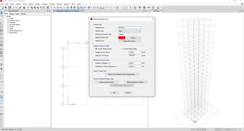
Using the material assignments, Rebar grade Fe415 is included in the material list. The default properties have been checked.
Step-4:
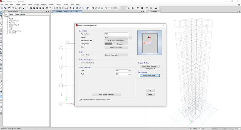
Define > Section properties > Frame sections
Using the rectangular concrete elements, Beam of size 300x400mm size has been added to the list. The design scope and assumed cover, rebar details have been mentioned.
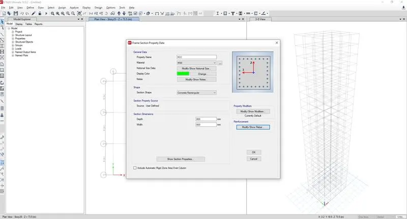
Using the rectangular concrete elements, Column of size 800x800mm size has been added to the list. The design scope and assumed cover, rebar details have been mentioned.
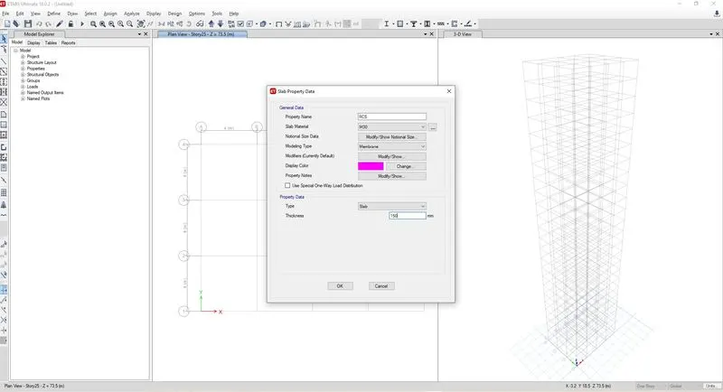
Define > Section properties > Slab sections
Using the membrane property, Slab size 150mm has been added to the list. "Membrane" property will help to consider only slab self weights and floor weights in analysis of structure while no stiffness component or flange advantage are considered during calculation.
Step-5:
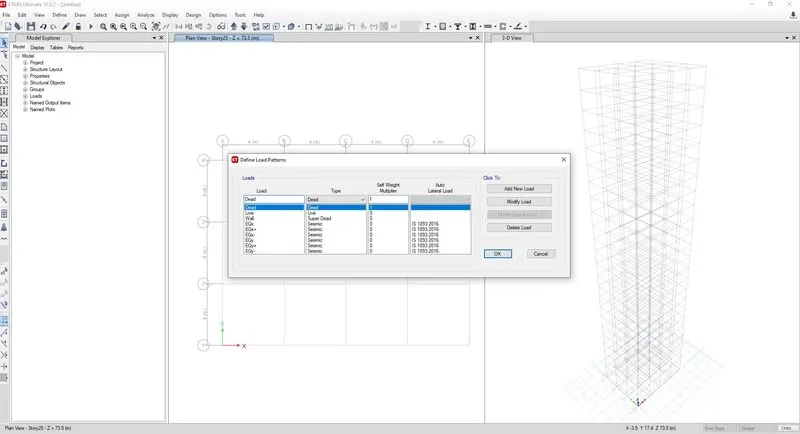
Define > Load patterns
With default dead load, additional wall load, live load, seismic load X direction (+/-), Seismic load Y direction (+/-) have been assigned. As the seismic data are not given in the question, it is assumed that zone factor 0.36, soil type-III, response reduction factor 5, program calculated time period.
Step-6:
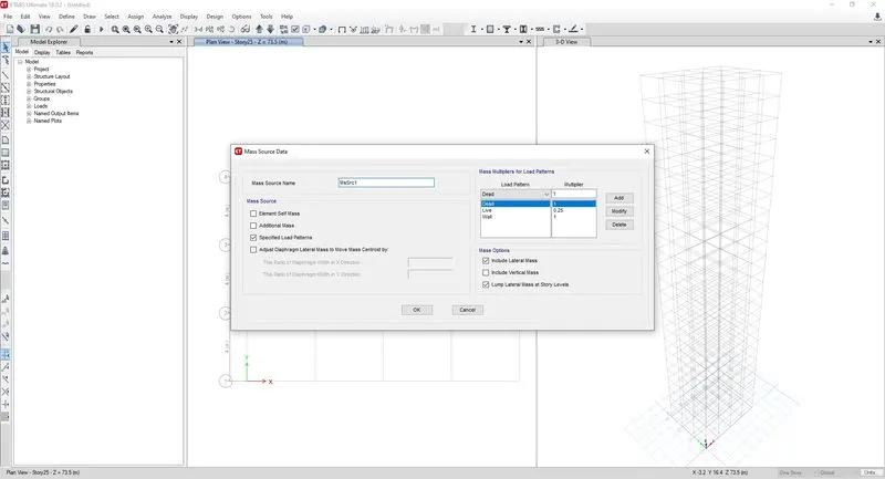
Define > Mass Source
As per the IS 1893 guideline, the reduced live load and all dead loads are considered for mass source. This proportion of building weight is mandatory to calculate seismic forces.
Step-7:
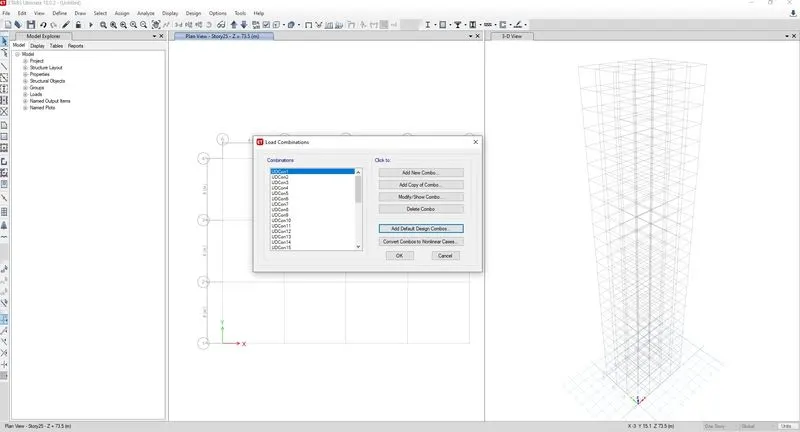
Define > Load combinations
As per the Indian standards IS 456 and IS 1893, the default combinations are generated using the ETABS predefined set.
Step-8:
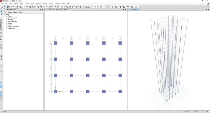
Using the quick draw column option, all the columns have been modelled keeping "all stories" ON.
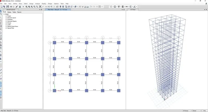
Using the quick draw bemas option, all the beams have been modelled keeping "all stories" ON.
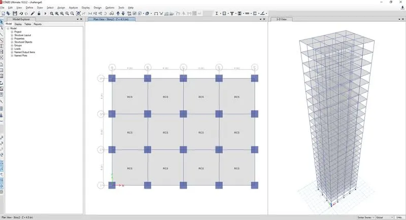
Using the quick draw floors option, all the slabs have been modelled keeping "Similar stories" ON.
Step-9:
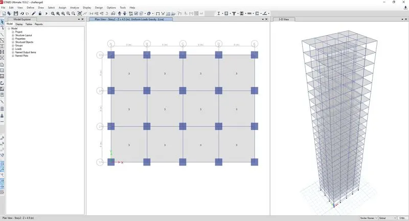
Select > Select > Object type > Floors
After selecting all floors, using "Assign > Shell loads > Uniform loads", Live load of 3 kN/sq.m is provided and verified at all levels.
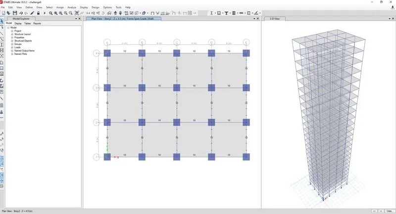
Select > Select > Object type > Beams
After selecting all beams, using "Assign > Frame loads > Distributed loads", Wall load of 10 kN/m is provided and verified at all levels.
Step-10:
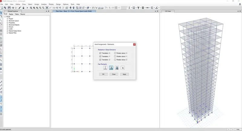
Using "Move down in List", base level is brought visible. All base supports are selected. Using "Assign > Joints > Restraints" option, pinned suport is assigned to all column bases as per the question description.
Step-11:
Using "Analyze > Check model" option, the modelled structure is verified without errors and warnings.
Step-12:
Using "Analyze > Run analysis" option, the model is analysed and deflection patterns, BMD/SFD patterns are cross chdcked logically. It is understood that the worked model provides reliable results.
Step-13:
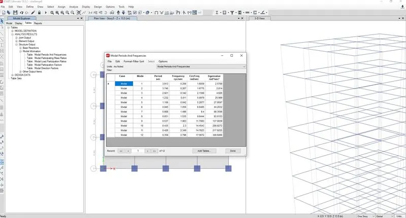
Display > Show tables > Analysis results > Structure output > Modal information > Modal periods and frequencies
The time periods for Fundamental Mode-1 Y direction and Fundamental Mode-1 X direction are noted from the table & found to be as follow.
Tx1 = 3.746 seconds
Ty1 = 3.913 seconds
Step-14:
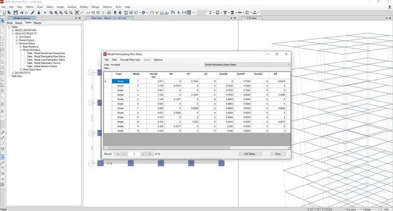
Display > Show tables > Analysis results > Structure output > Modal information > Modal participation mass ratios
From the table, the natural time period for Mode-1 translation and torsion DOF are noted as follow.
Tx1 = 3.746 seconds
Ty1 = 3.913 seconds
Txy1 = 2.921 seconds
Thus we can understand, the torsional time period is less than the two translation time period as required by IS 1893 provision Table-5.
Also, the mass participation ratios for first three modes are noted as follow.
Tx1 = 0.7635
Tx2 = 0.1027
Tx3 = 0.0382
By summing the three mode mass ratios, we are getting Tx1 + Tx2 + Tx3 = 0.9044, which means first three modes of seismic oscillation contribute more than 65% of building weight as per ETABS analysis. So the code requirement is satisfied.
As we already know the X and Y direction time periods, they differ only by 4.3%. So the code requirement of minimum 10% is not satisfied.
Step-15:
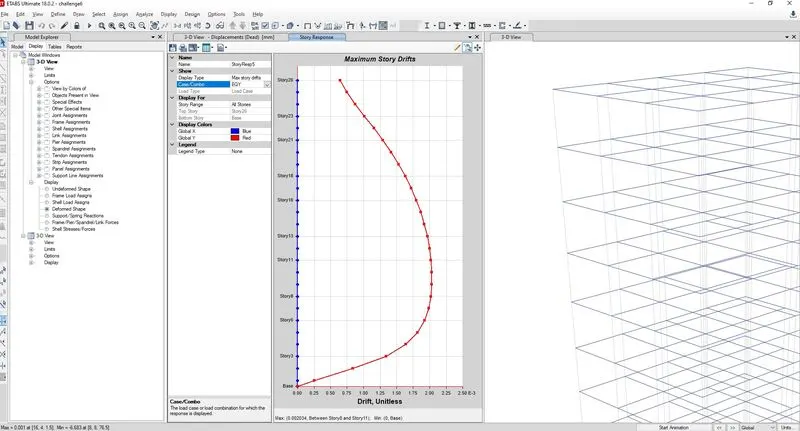
As suggested by the question description, the storey drift for serviceability Base shear case (EQX or EQY) is tabulated from following tool path
Display > Storey response plot
Keeping load case "EQY" and switching to "Max Story drift", the maximum drift value is noted as 0.002034.
As per clause 7.11.1.1, the maximum inter storey drift is limited to 0.004 for each storey height. But the ETABS value is just 0.002 which is lesser than the code limits. Hence OK.
Conclusion:
Thus, the ETABS model is completed and anlaysed. The requested data are verified as per Indian seismic standards. But the time period separation of at least 10% is not achieved in the given practice.