Project 2
Aim:
To draw the preliminary scheme for the horizontal and vertical allignments for the proposed bridge. And to model the bridge with relevant stages from diaphragm to live load application and to design the concrete, prestress and steel components with respect to relevant indian standards.
Since the bridge is symmetrical, only representative spans are decided to be analysed and designed (few from curved range and few from straight range).
Horizontal allignment of proposed bridge: (from abutment to central steel span)
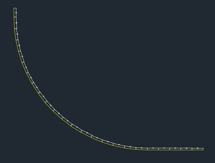
Vertical allignment of proposed bridge: (from abutment to elevated level of deck)

Only few horizontal allignment and vertical allignment spans are going to be modelled and designed as per following arrangement.

Adopted construction stages as per given details:
(i) Solid diaphragm + post tensioning only stage
(ii) Precast girders + prestress only (to be checked for fresh concrete slab above)
(iii) Composite steel section with joint in overhanging precast girder (to be checked for fresh concrete slab above)
(iv) With concrete slab deck (to be checked for all other imposed loads like asphalt, curb & barrier)
(v) Live load with continuous and discontinuous checks
Loads to be calculated in each stages:
Stage-1
Only solid diaphragm has to be modelled with post-tension assignment. So no load needs to be applied
Stage-2
fresh concrete has to be cast over precast girders. This has to be checked as loading. 8 meter wide and 200mm thick concrete.
8 x 0.2 x 25 = 40 kN/m
We have 2 tub sections, so each precast section will carry 20 kN/m
Stage-3
fresh concrete has to be cast over steel box girders. This has to be checked as loading. 8 meter wide and 200mm thick concrete.
8 x 0.2 x 25 = 40 kN/m
We have 2 box girders, so each composite girder will carry 20 kN/m
Stage-4
After deck slab hardened, it will behave monolithic with the precast and composite steel. But the above curb, barrier, asphalt are permanent imposed loads need to be applied.
Curb = 0.3 x 0.35 x 25 = 2.63 kN/m
Barrier = 4 kN/m
Asphalt = 0.127 x 18 = 2.3 kN/m2 (area load)
Stage-5
After all the dead load, surfacing and accesories installment, the vehicle (or) live loads has to be checked for both continuous and discontinuous conditions.
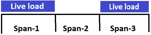
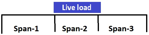
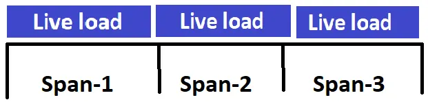
The preferred cases for checking live load as follow,
(a) Odd spans
(b) Even spans
(c) All spans
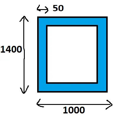
The initial sizing for proposed bridge components:
a) Composite steel plate
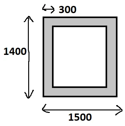
b) Precast Tub wall
300mm thick wall is recommended to place tendon.
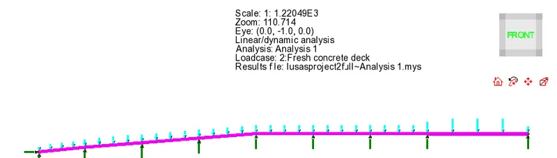
Stage-2 and Stage-3 Construction phase:
(i) Precast girders & Steel girders with 20 kn/m fresh deck concrete load
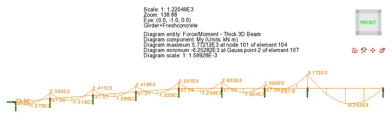
(ii) Bending moment for selfweight+deck concrete load combination:
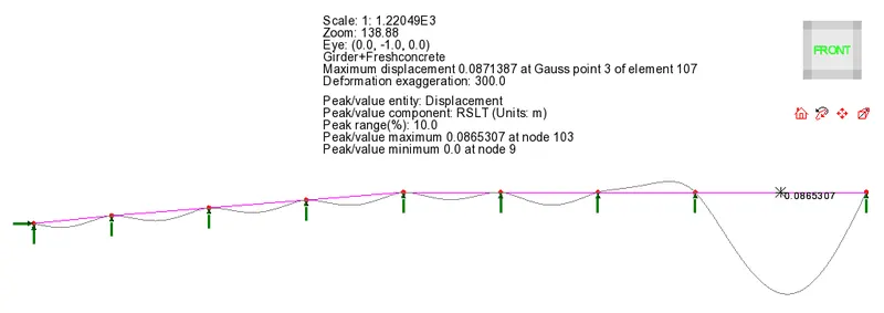
(iii) Deflection for selfweight+deck concrete load combination:
Stage-4 final construction stage:
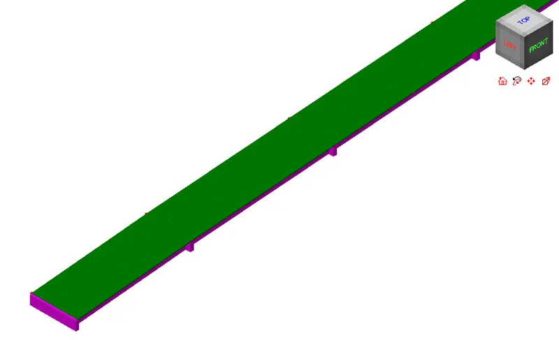
(i) full deck slab
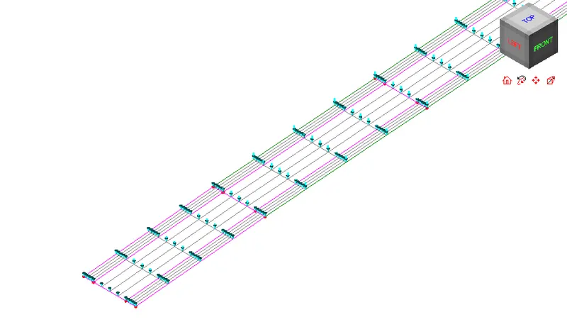
(ii) Asphalt loading + curb and barrier loading
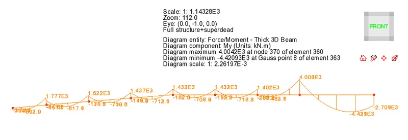
(iii) Bending moment due to structure + superdead loads:
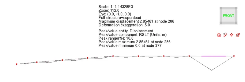
(iv) Deflection due to structure + superdead loads:
Stage-5 Live load check:
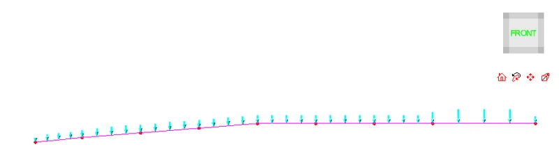
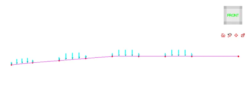
(i) Live load all span
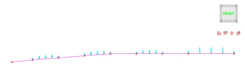
(ii) Live load even span
(iii) Live load odd span
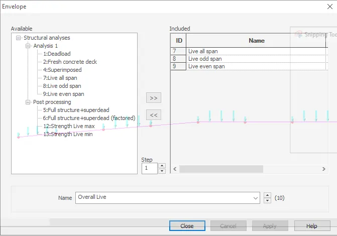
(iv) Envelope for the maximum and minimum live load envelope
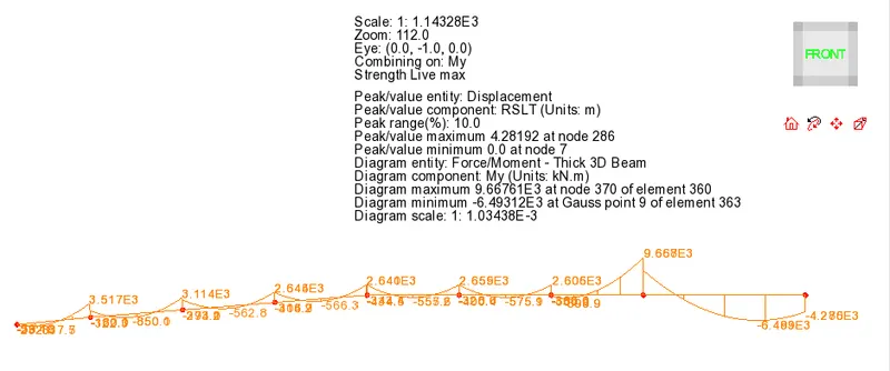
(v) factored bending moment for structure + superdead load + live maximum hogging:
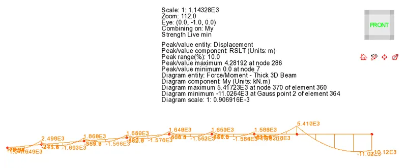
(vi) factored bending moment for structure + superdead load + live maximum sagging:
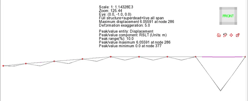
(vii) deflection for structure + superdead load + live maximum sagging: