Reinforcement detailing of Columns from ETABS output
Aim:
To analyse the given ETABS model and to extract the design results and detailing of two mentioned RC columns. Also the calculation for special confining reinforcement has to be ensured based on clause 8.1 of IS 13920-2016.
Design of RC columns:
Step-1:
Analyse > Check model
Analyse > Run analysis
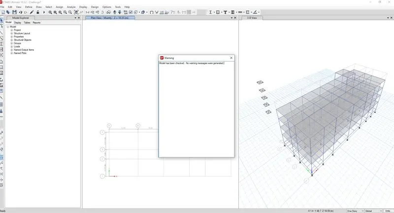
Using the above toolpath, the given model is first checked for its errors and warnings. The model is found to be OK. The Model has completed analysis.
Step-2:
Design > Frame design Preference
Design > Design combination
Design > Start design/check
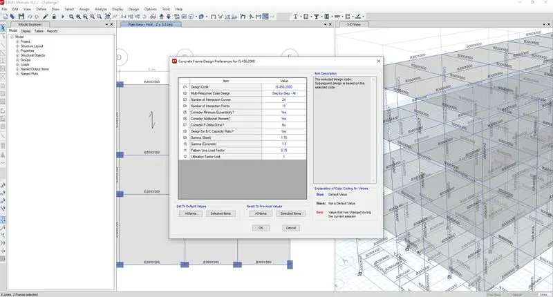
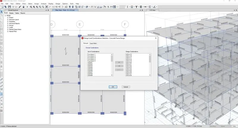
Using the above toolpath, the given ETABS model is ensured for its design code assignment and combination assignments. Then the ETABS model is design initiated.
Step-3:
Design > Verify all members passed
Design > Display design info > Flexural reinforcement
Design > Display design info > Shear reinforcement
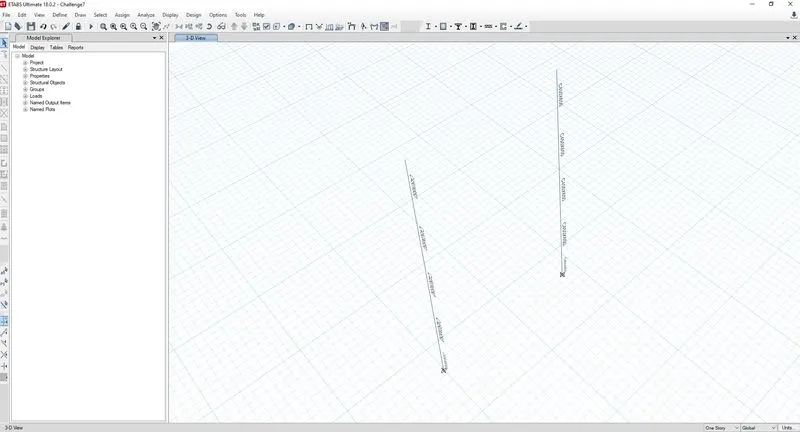
With "View selected objects only" tool, the two columns (Grids-3/A and 3/B) are viewd. Using the above toolpath, the Model is verified for all members satisfy design criteria. The design flexural reinforcement and shear reinforcement are noted from the Frame design output for the requested RC columns.
Step-4:
As per the noted rebar outputs, the Longitudinal sections for those two RC beams are drawn using AutoCAD software and detailing is done complying IS 13920-2016 requirements.
Note: Drawing is attached as PDF format.
Step-5:
As per clause 8.1 of IS13920-2016, the special confining reinforcement is calculated and verified with the drawing detail.
As per cluase 8.1 section a), the confining reinforcement length `l_o`should be at least
i) larger dimension of frame member (650mm)
ii) 1/6th of clear span (575mm)
iii) 450mm
So `l_o`= 650mm
As per cluase 8.1 section b), the maximum spacing of confining reinforcement shall be
i) 1/4th of minimum member dimension (112.5mm)
ii) 6 times of smallest longitudinal rebar (120mm)
iii) 100mm
So maximum shear link spacing maintained = 100mm
Minimum special confining reinforcement should be maximum of (a) and (b)
(a) `A_(sh)`= 0.18 `s_v h (f_(ck)/f_y) ((A_g/A_k)-1)`
(b) `A_(sh)`= 0.05 `s_v h f_(ck)/f_y`
(a) `A_(sh)`= 631 sq.mm/m
(b) `A_(sh)`= 337 sq.mm/m
Required minimum special confining reinforcement at joint `A_(sh)`= 631 sq.mm
Provided shear reinforcement at joint = `(1000/100)`x 4 legs x area of 8mm dia rebar (50.3 sq.mm) = 2010 sq.mm
Hence OK.
Conclusion:
Thus the detailing of two RC columns were done using AutoCAD and special confininf reinforcement is verified with respect to IS13920 clause 8.1.