Creation of Multiple viewports, Scaling the drawing and setting in Template in AutoCad
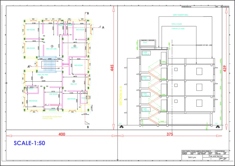
Aim:Â To create layout of the Plan and Section A of the project in Challenge 7 as shown in the figure above, in AutoCAD.
Introduction:Â The layout is created in AutoCAD using the template Tutorial-mArch.dwt in a scale 1:50 that given in the Figure. The procedure is explained in detail with diagrams of each step and the final result is given.
Procedure:
STEP 1
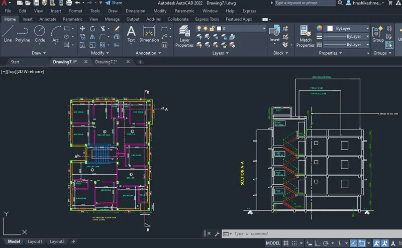
- Go to START MENU, select AutoCAD 2022.
- Go to Application Menu and select Open.
- Open the Week 7 drawing.
Â
Â
Â
Â
Â
STEP 2
- Zoom in to the plan.
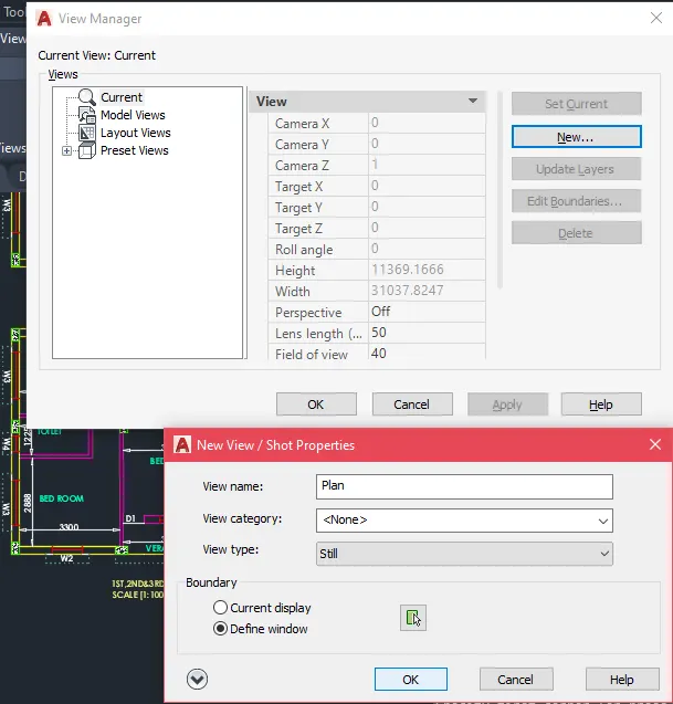
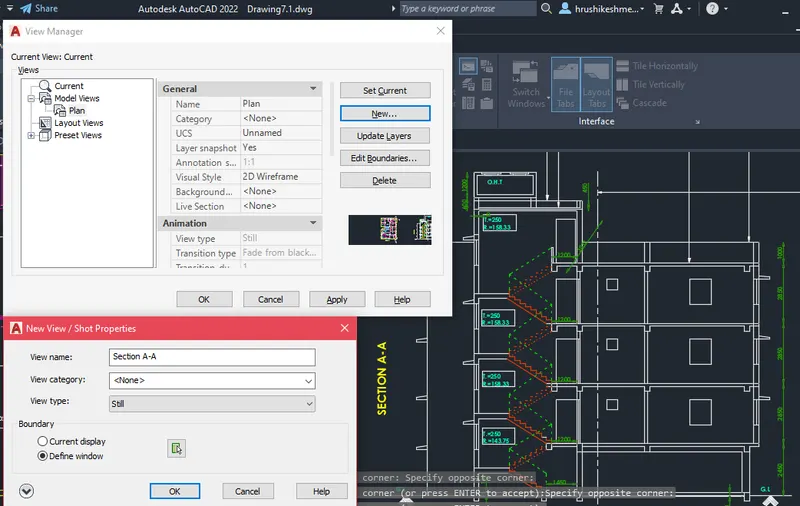
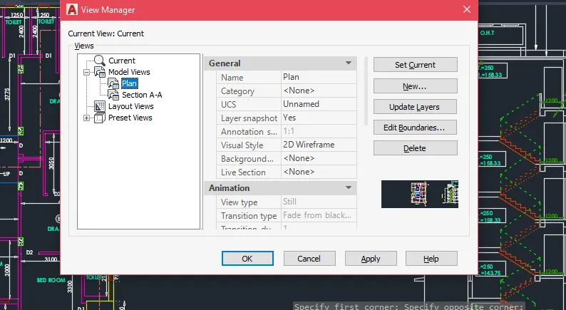
- To create views:Â Command " View">Appear the View dialog box>Named Views>New View.
- In the New View dialog box enter view name as Plan and click OK.
- Repeat the same process to create Section A-A view.
Â
Â
Â
STEP 3
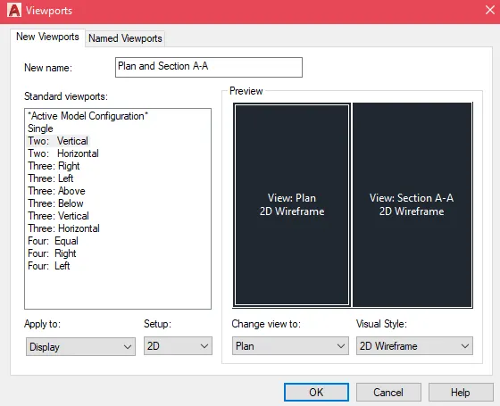
- Go to Ribbon>View>View Configuration.
- Select Two:Vertical from the drop down list.
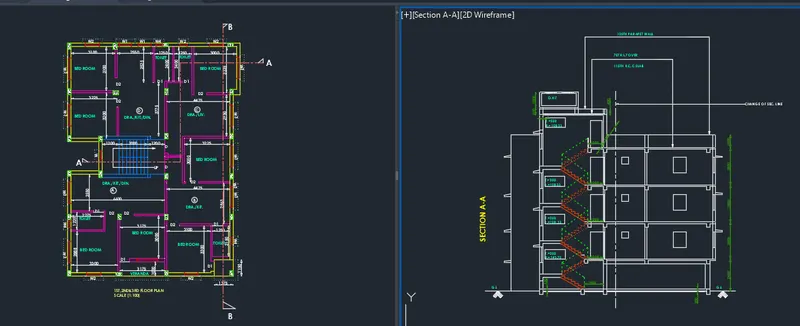
- In the left window select the Plan View and in the right window select the Section A view.
- Click on the Named option in the Model Viewports panel.
- Click on New Viewports.
- Enter the name as Plan and Section, Click OK.
Â
Â
Â
Â
Â
 STEP 4
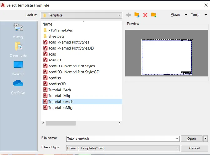
- To create a new Layout, enter LAYOUT in the command line.
- Select the Template option.
- Select the Tutorial-mArch template.
- Click Open.
- Right click on the Layout tab, select the rename option and enter new name as 'Plan and Section'.
Â
Â
Â
STEP 5
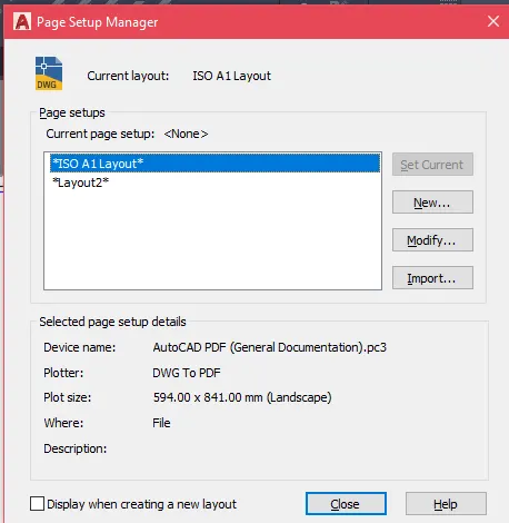
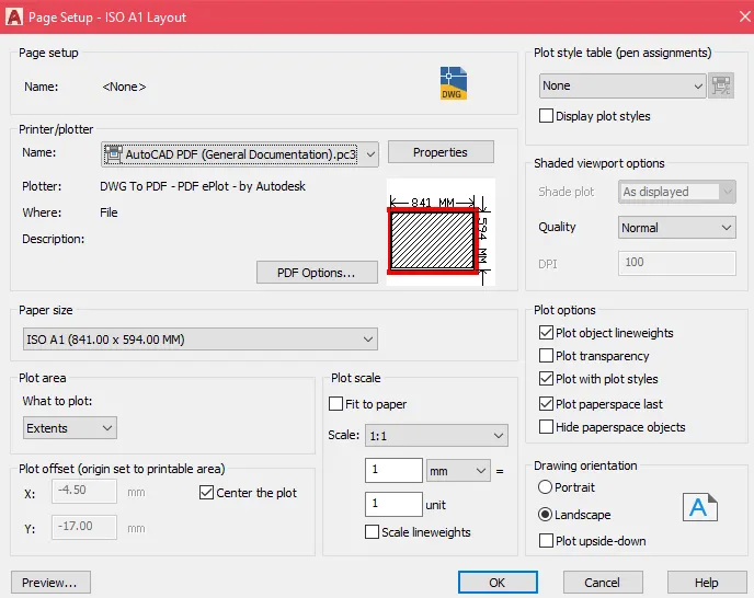
- Enter PAGESETUP in the command line.
- Select the specifc layout, and click on Modify.
- Select the ISO A1 paper size.
- Click OK.
Â
Â
Â
Â
Â
Â
Â
Â
STEP 6
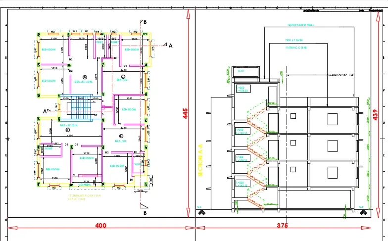
- Select the Rectangle tool by entering ‘REC’ command in the command tab.
- Specify the first point at the inner edge of the .
- Select Dimensions option in the command line.
- Specify length of rectangle as 400 in the command line.
- Specify width of rectangle as 445 in the command line.
- Move the cursor downwards and click ENTER.
- Again, Select the Rectangle tool by entering ‘REC’ command in the command tab.
- Specify the first point at the inner edge of the .
- Select Dimensions option in the command line.
- Specify length of rectangle as 375 in the command line.
- Specify width of rectangle as 445 in the command line.
- Move the cursor downwards and click ENTER.
- Go to Layout>Insert View.
- Select the saved Plan and Section views and insert them to their respective boxes.
- Enter MS in the command line.
- Open Layer Manager dialog box and change the Viewport Layer Colors fo rboth the viewports to darker shades.
- Select the views and scale them as required individually.
- Enter PAN in the command line to adjust the position of the drawing inside the viewport.
- Lock view.
Â
Â
Â
STEP 7
- Enter PS in the command line.
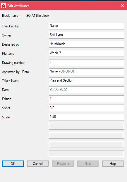
- Enter ATTEDIT in the command line.
- Select the block reference as the template title box.
- In the Edit Attributes dialog box enter the necessary details.
- Click OK
- Click OK.
Â
Â
Â
Â
Â
STEP 8
- Select the Dimension and Text layer.
- Enter ‘DSTY’ command in the command tab to open the Dimension Style Manager dialog box.
- Select Annotative option and click on the Modify tab.
- Under the Symbols and Arrows option change the Arrow size to 20.
- Under the Text option change the Text height to 20.
- Click OK. Then click on Set Current and Close the dialog box.
- Select the Dimension tool by entering 'DIMLIN' in the command line.
- Select the first point and second point of the object to be measured, then drag the dimension line to the desired location.
- Repeat for all the objects to be measured.
- Go to Annote>Text Style>Annotative.
- Enter 'MTEXT' command in the command line.
- Specify the start point of text as required.
- Enter ED in the command promt and edit the text boxes as required.
- Click Enter and press Esc.
- Save the drawing.
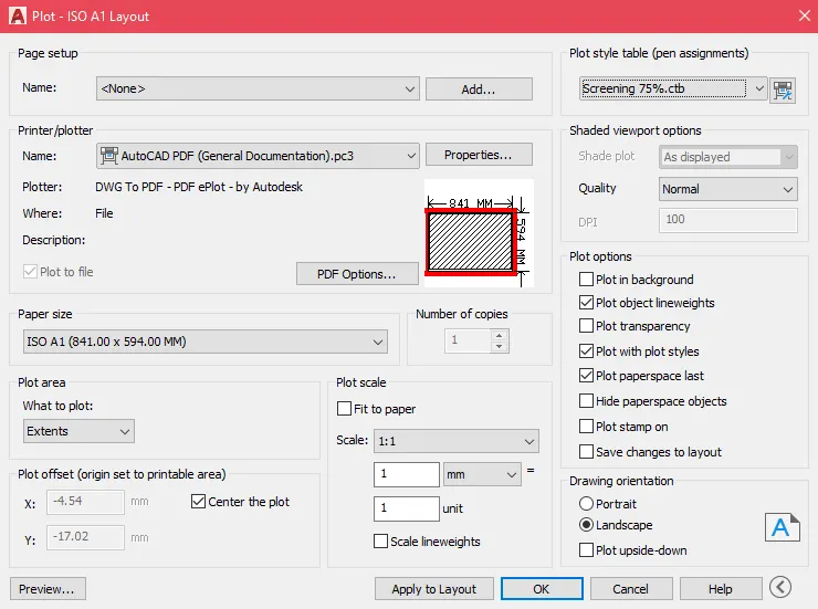
- Enter PLOT in the command line.
- In the Plot dialog box make necessary changes, check the preview, press Esc.
- Click OK.
- Save the Pdf file.
Â
Â
Â
RESULT:-
Â
Â
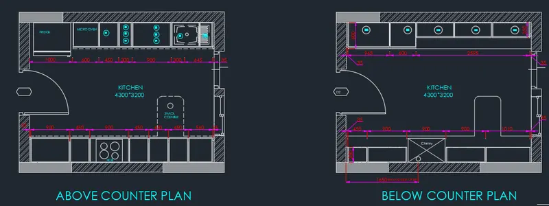
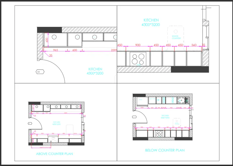
Aim:Â To create layout of the Kitchen in Challenge 9 as shown in the figure above, in AutoCAD.
Introduction:Â The layout is created and plotted in AutoCAD. The procedure is explained in detail with diagrams of each step and the final result is given.
Procedure:
STEP 1
- Go to START MENU, select AutoCAD 2022.
- Go to Application Menu and select Open.
- Open the Week 10 Kitchen layout drawing.
Â
Â
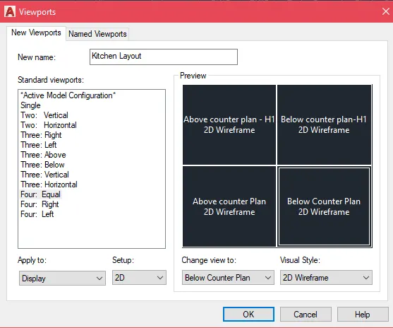
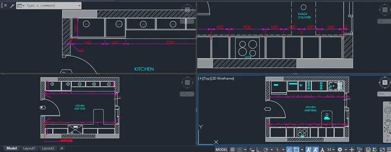
- Go to Ribbon>View>View Configuration.
- Select Four:Equal from the drop down list.
- In the windows select and zoom in on the views as shown in the given figure.
- Click on the Named option in the Model Viewports panel.
- Click on New Viewports.
- Enter the name as Kitchen layout1, Click OK
Â
Â
Â
STEP 2
- Select the Above counter plan viewport.
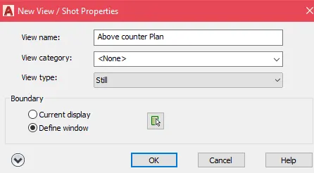
- To create views: Ribbon>View>Named Views>New View.
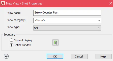
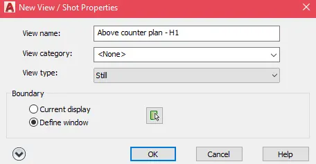
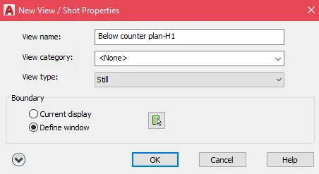
- In the New View dialog box enter view name as Above Counter Plan and click OK.
- Repeat the same process to create Below Counter Plan, Above counter plan_H1, Below Counter Plan_H1 views.
Â
Â
Â
Â
Â
STEP 3
- To create a new Layout, enter LAYOUT in the command line.
- Select the New option.
- Enter new layout name as Kitchen Layout1.
- Press Enter.
- Go the Layout page and Select and delete the default model view.
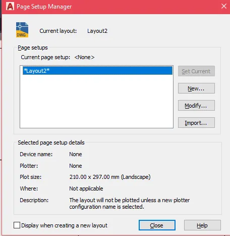
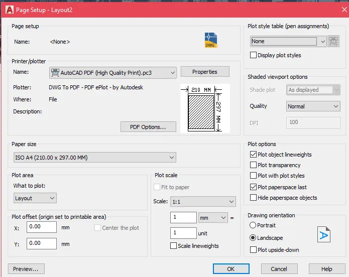
- Enter PAGESETUP in the command line.
- Select the specifc layout, and click on Modify.
- Select the ISO A4 paper size.
- Click OK
Â
Â
Â
Â
Â
STEP 4
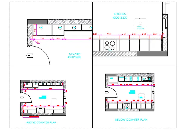
- Go to Layout>Insert View.
- Select the saved views and insert them in the layout according to the given figure.
- Resize the viewports as required.
- Enter MS in the command line.
- Open Layer Manager dialog box and change the Viewport Layer Colors fo rboth the viewports to darker shades.
- Select the views and scale them as required individually.
- Enter PAN in the command line to adjust the position of the drawing inside the viewport.
- Lock views.
- Enter PS to go to paper space.
Â
Â
Â
STEP 5
- Go to Annote>Text Style>Annotative.
- Enter 'MTEXT' command in the command line.
- Specify the start point of text as required.
- Enter ED in the command promt and edit the text boxes as required.
- Click Enter and press Esc.
- Save the drawing.
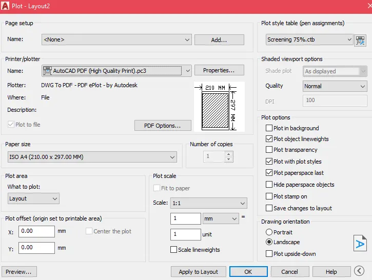
- Enter PLOT in the command line.
- In the Plot dialog box make necessary changes, check the preview, press Esc.
- Click OK.
- Save the Pdf file.
Â
Â
Â
RESULT:-
Â
Â
Â
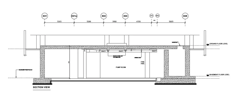
3.Aim:Â To create layout of the section created Challenge 9 as shown in the figure above, in AutoCAD.
Introduction:Â The layout is created and plotted in AutoCAD. The procedure is explained in detail with diagrams of each step and the final result is given.
Procedure:
STEP 1
- Go to START MENU, select AutoCAD 2022.
- Go to Application Menu and select Open.
- Open the Week 10 Industrial Section drawing.
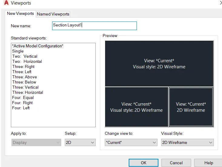
- Go to Ribbon>View>View Configuration.
- Select Three:Above from the drop down list.
- In the windows select and zoom in on the views as shown in the given figure.
- Click on the Named option in the Model Viewports panel.
- Click on New Viewports.
- Enter the name as Section layout1, Click OK
Â
Â
Â
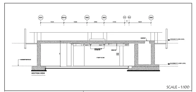
STEP 2
- Select the Elevation viewport.
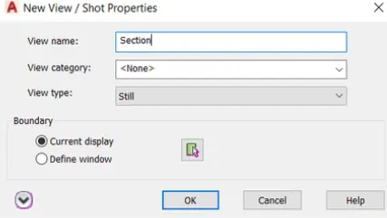
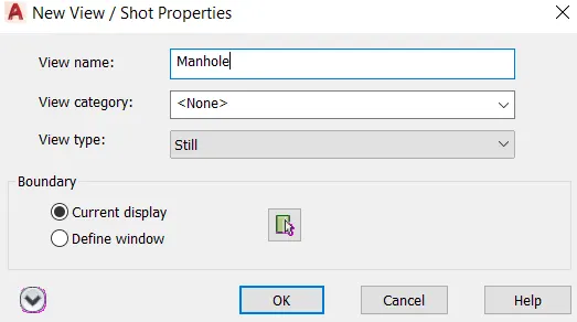
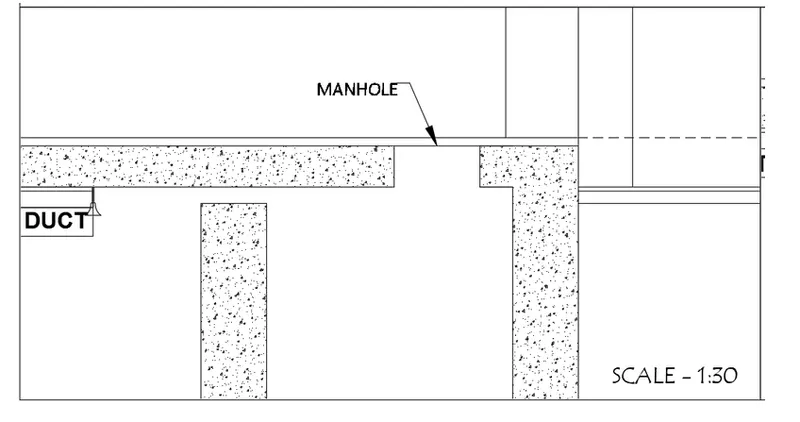
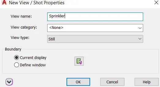
- To create views: Ribbon>View>Named Views>New View.
- In the New View dialog box enter view name as Section and click OK.
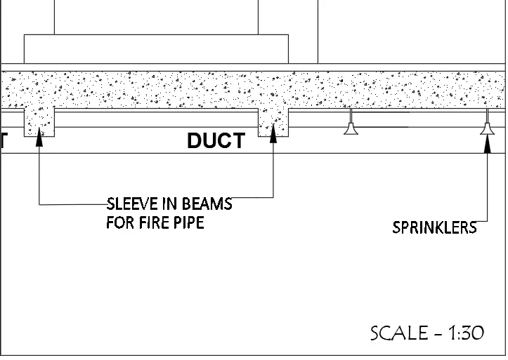
- Repeat the same process to create Manhole, Sprinkler views.
Â
Â
Â
Â
Â
Â
Â
STEP 3
- To create a new Layout, enter LAYOUT in the command line.
- Select the New option.
- Enter new layout name as Section Layout1.
- Press Enter.
- Go the Layout page and Select and delete the default model view.
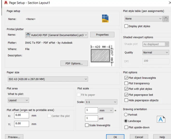
- Enter PAGESETUP in the command line.
- Select the specifc layout, and click on Modify.
- Select the ISO A3 paper size.
- Click OK.
Â
Â
Â
STEP 4
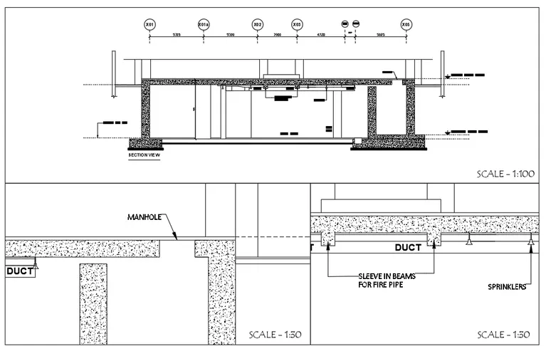
- Enter MV in the command line.
- Specify corners and Viewport.
- Repeat MV command twice more to create three viewports.
- Enter MS in the command line.
- Select the viewports and assign the specific views to the viewports.
- Open Layer Manager dialog box and change the Viewport Layer Colors for both the viewports to darker shades.
- Select the views and scale them as required individually.
- Enter PAN in the command line to adjust the position of the drawing inside the viewport.
- Lock views.
- Enter PS to go to paper space
Â
Â
Â
STEP 5
- Go to Annote>Text Style>Annotative.
- Enter 'MTEXT' command in the command line.
- Specify the start point of text as required.
- Type in the Text and copy the text box to required locations.
- Enter ED in the command promt and edit the text boxes as required.
- Click Enter and press Esc.
- Save the drawing.
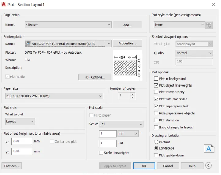
- Enter PLOT in the command line.
- In the Plot dialog box make necessary changes, check the preview, press Esc.
- Click OK.
- Save the Pdf file.
Â
Â
Â
Â
RESULT:
Â
Â
Â
 FINAL RESULTS:-
 RESULT:1
Â
 RESULT:2
Â
 RESULT:3
Â