Analysis & Design of RCC shear walls in the model using ETABS
Aim:
To analyse the given Model and to extract the reinforcement details for specified RC wall. and to detail the RC wall using AUtoCAD with compiance to ductility IS 13920-2016 standard.
Extracting Design details from ETABS:
Step-1:
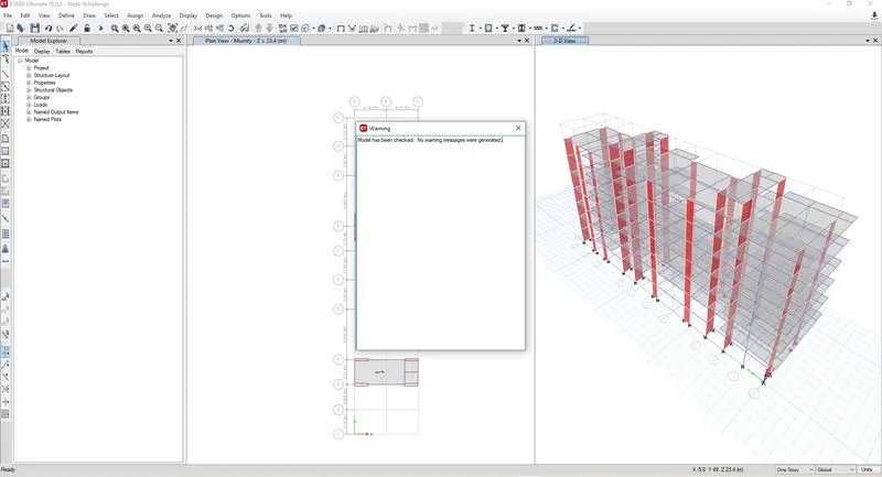
Analyse > Check model
Using above toolpath, the given model is checked without errors.
Step-2:
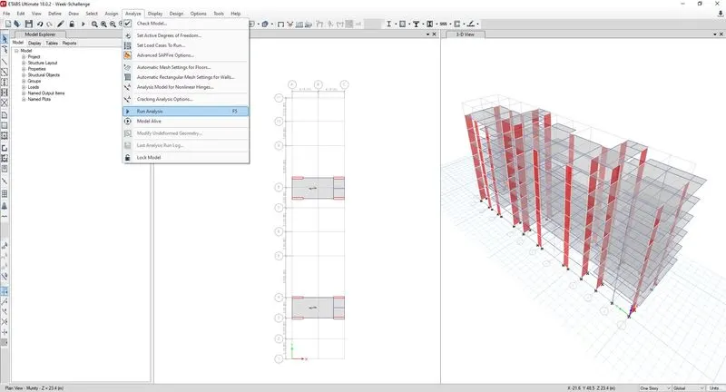
Analyse > Run analysis
Using above toolpath, the given model is analysed and deflection moment results are once verified logically.
Step-3:
Select > Select > Properties > Wall sections
Using above toolpath, the specified wall is selected.
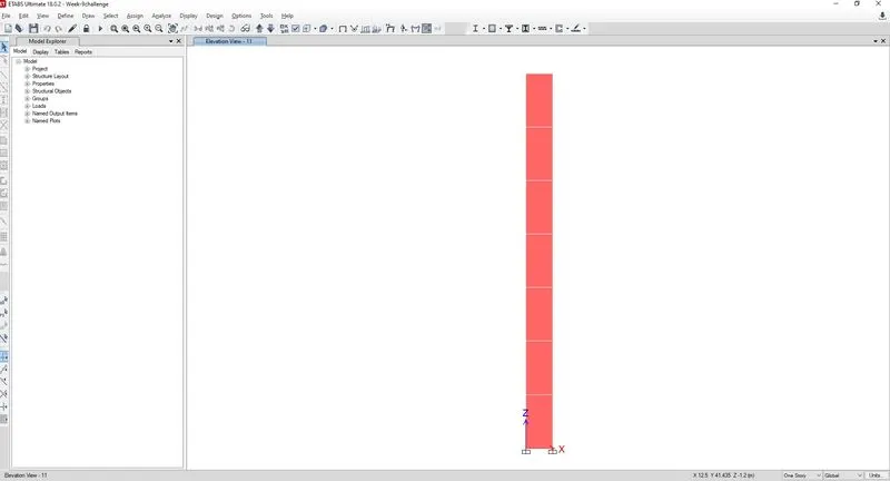
Right click on window > View selected items only
Using the above toolpath, the selected RC wall is viewed for better visibility of results.
Step-4:
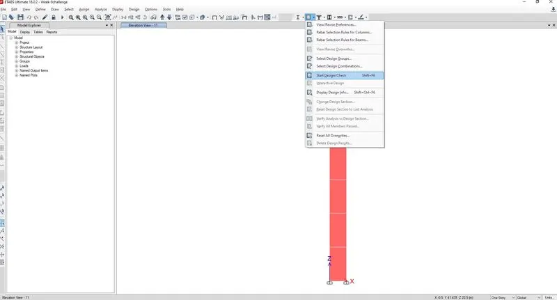
Design > Shear wall design > Start design/check
Using above toolpath, the RC walls are initiated for design based on IS456 and IS13920 criteria.
Step-5:
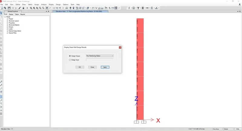
Display design info > Design output > Pier reinforcement ratio
Using above toolpath, the longitudinal reinforcement ratio is swithed ON and noted down
Step-6:
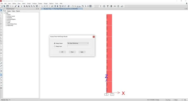
Display design info > Pier shear reinforcing
Using above toolpath, shear reinforcement details of RC wall is viewed and noted.
Step-7:
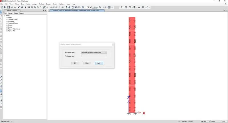
Display design info > Pier edge/Boundary zone widths
Using above toolpath, the boundary element widths of RC wall at each level is viewed and noted.
Step-8:
Reviewing the design output of ETABS, the boundary element widths are fixed with two values respectively 450mm (from base to 1st floor) and 300mm (1st floor to terrace). The longitudinal rebar and shear rebar also categorised in same respect and detailed using AutoCAD software.
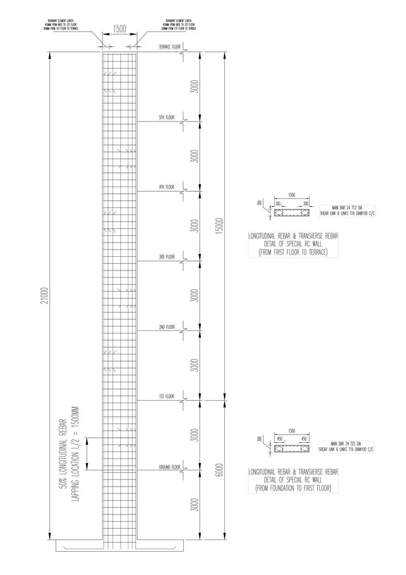
Verification with IS13920-2016:
a) Overall height of wall h = 21000mm, Length of wall L = 1500mm
Ratio (h/L) = 21000/1500 = 14 > 2
The given RC wall is slender.
b) The largest diameter than can be used in RC wall should not exceed 1/10th of thickness of wall. So 300/10 = 30mm
We used 25mm dia rebar in the detailing. Hence OK.
c) The maximum spacing of longitudinal / transverse rebar should not exceed (i) 1/5th of horizontal length(L)=1500/5 =300mm
(ii) 3 times of thickness (t) = 3 x 300 = 900mm
(iii) 450mm
So we have to adopt maximum 300mm spacing both for vertical and horzontal rebar inside RC wall.
d) Minimum horizontal reinforcement calculation as per Table-1 of IS13920-2016
`(rho_h)_min`= 0.0025 + 0.5`(h_w / L_w - 2) (rho_h - 0.0025)`
= 0.01672 of cross section of RC wall
= 1500 x 300 x 0.01672 = 7524 sq.mm for entire RC wall height.
= 7524 / 21 = 358 sq.mm /meter height of RC wall
We already provided 16mm dia at 100 mm c/c spacing which will give = 1000/100 x 2 x 201 = 4020 sq.mm
Hence OK.
e) Minimum boundary reinforcement calculation as per Table-1 of IS13920-2016
`(rho_(v,be))_min`= 0.008
= 0.008 x 300 x 300 = 720 sq.mm
We already provided minimum 8 numbers 12mm dia rebar = 8 x 113 = 904 sq.mm
Hence OK.
f) Minimum web reinforcement calculation as per Table-1 of IS13920-2016
`(rho_(v,web))_min`= 0.0025
= 0.0025 x 900 x 300 = 675 sq.mm
We already provided minimum 8 numbers 12mm dia rebar = 8 x 113 = 904 sq.mm
Hence OK.
g) Minimum overall RC wall vertical reinforcement calculation as per Table-1 of IS13920-2016
`(rho_(v,net))_min`= 0.0025 + 0.01375 `(t_w / L_w)`
= 0.00525 times of wall cross section
= 0.00525 x 1500 x 300 = 2363 sq.mm
We already provided minimum 24 numbers 12mm dia rebar = 24 x 113 = 2712 sq.mm
Hence OK.
h) Boundary element special confining reinforcement as per Clause 10.4.4 of IS13920-2016:
`A_(sh) = 0.05 S_v h (F_(ck) / f_y)`
Maximum spacing of confinement is 100mm as per drawing
h = minimum clear distance between longitudinal rebar = 150mm say
`A_(sh) =`45 sq.mm
We already provided two closed links of 16mm dia = 2 x 201 = 402 sq.mm
Hence OK.
Conclusion:
Thus we have designed the specified RC wall and detailed using AutioCAD software. Also the clauses from ductility code Indian standard IS13920-2016 are verified for the RC wall detailing.