Reinforcement Detailing of Beams from ETABS output
Aim:
To analyse the given ETABS model and to extract the design results and detailing of two mentioned RC beams. Also the design recheck for Grid-A RC beam has to be done.
Design of RC beams:
Step-1:
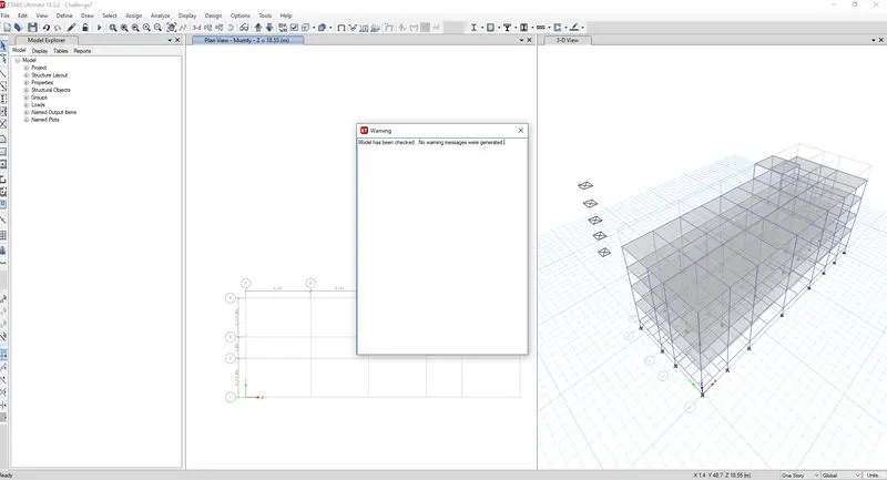
Analyse > Check model
Analyse > Run analysis
Using the above toolpath, the given model is first checked for its errors and warnings. The model is found to be OK. The Model has completed analysis.
Step-2:
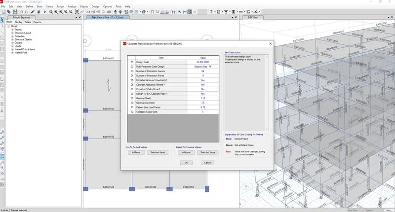
Design > Frame design Preference
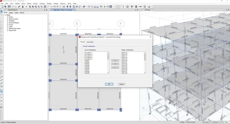
Design > Design combination
Design > Start design/check
Using the above toolpath, the given ETABS model is ensured for its design code assignment and combination assignments. Then the ETABS model is design initiated.
Step-3:
Design > Verify all members passed
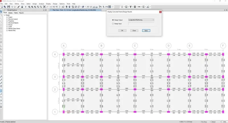
Design > Display design info > Flexural reinforcement
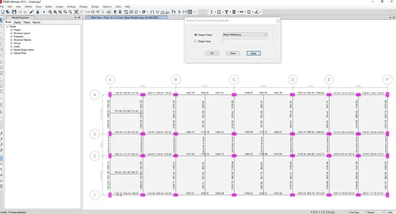
Design > Display design info > Shear reinforcement
Using the above toolpath, the Model is verified for all members satisfy design criteria. The design flexural reinforcement and shear reinforcement are noted from the Frame design output for the requested RC beams along Grid-A and Grid-3.
Step-4:
As per the noted rebar outputs, the Longitudinal sections for those two RC beams are drawn using AutoCAD software and detailing is done complying IS 13920-2016 requirements.
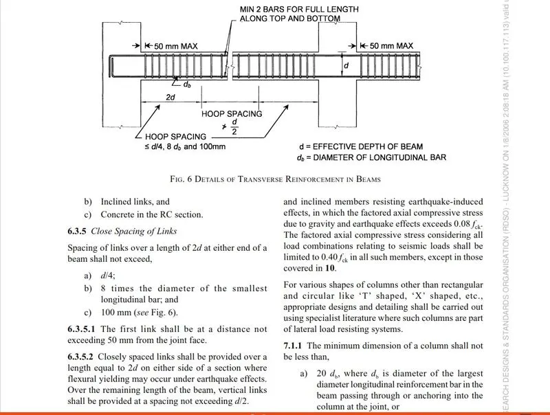
Note: Drawing is attached as PDF format.
The scope of failure in midspan of Grid-A RC beam:
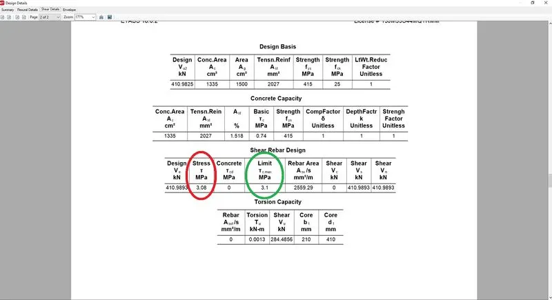
It is noted that central span of Grid-A RC beam is nearly failing due to higher shear stress. As per the above shear force value (3.08 MPa) against the maximum allowable shear stress (3.1 MPa), is almost failing but passes numerically. This design shear force is arrived in philosophy of Capacity design concept. This can be resolved in any of the following process.
- a) Optimizing provided flexural reinforcement
- b) reducing depth of RC beam which in turn reduce stiffness and flexure requirement
- c) increasing concrete grade will increase allowable shear stress limit.
Calculation of Design shear force of RC beams complying clause 6.3.3 (b) of IS 1920-2016:
Grid-A RC beam:
Support top flexural reinforcement as per Drawing- 2098 sq.mm
Support bottom flexural reinforcement as per Drawing- 1960 sq.mm
Using Annexure-G of IS-456 indian standard, the moment capacity of RC beams are calculated as follow.
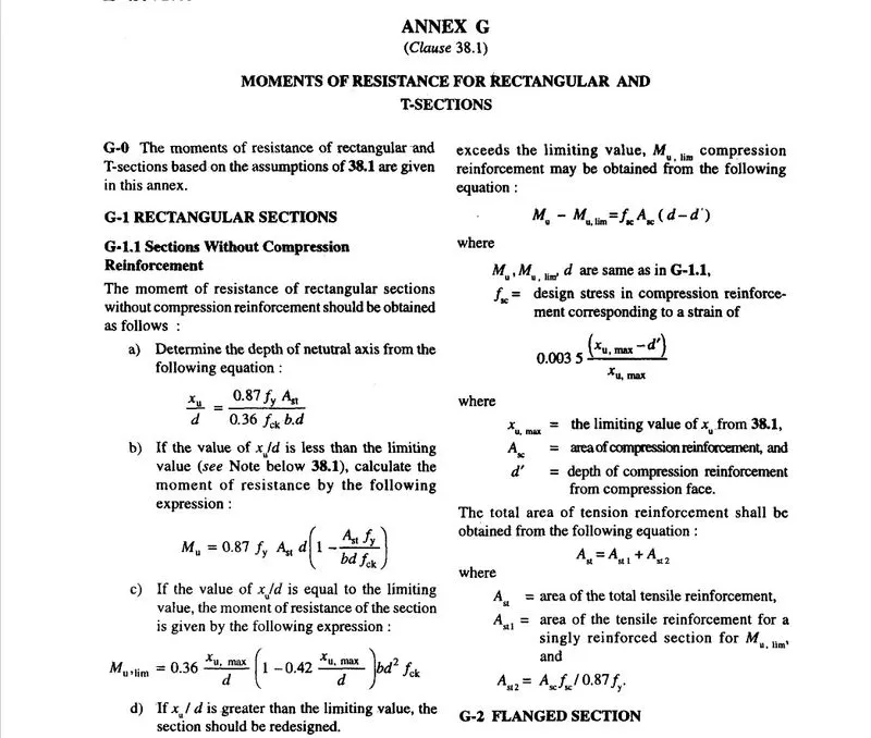
Hogging Moment capacity of RC beam (`M_u^s`)- 283 KNm
Sagging Moment capacity of RC beam (`M_u^h`)- 272 KNm
The demand Shear force for 1.2(DL+LL) combination is derived from ETABS model as follow.
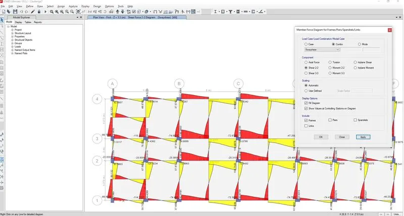
Demand shear force from ETABS analysis (`V_(u,a)^(D+L)`= `V_(u,b)^(D+L)` = 22.65 KN
Clear span (`L_(AB)`= 2.35 meter
Using clause 6.3.30 of IS13920-2016 indian standard, the sway shear force is calculated as follow.
1. Sway shear at Left as per IS 13920-2016 = 353.29 kN
2. Sway shear at Right as per IS 13920-2016 = 353.29 kN
Required shear reinforcement as per calculation = 2174 sq.mm per meter run
Provided shear reinforcement as per drawing = 4020 sq.mm per meter run
Hence OK.
Grid-3 RC beam:
Support top flexural reinforcement as per Drawing- 2098 sq.mm
Support bottom flexural reinforcement as per Drawing- 1030 sq.mm
Using Annexure-G of IS-456 indian standard, the moment capacity of RC beams are calculated as follow.
Hogging Moment capacity of RC beam (`M_u^s`)- 283 KNm
Sagging Moment capacity of RC beam (`M_u^h`)- 171 KNm
The demand Shear force for 1.2(DL+LL) combination is derived from ETABS model as follow.
Demand shear force from ETABS analysis (`V_(u,a)^(D+L)`= `V_(u,b)^(D+L)` = 150.65 KN
Clear span (`L_(AB)`= 7.365 meter
Using clause 6.3.30 of IS13920-2016 indian standard, the sway shear force is calculated as follow.
1. Sway shear at Left as per IS 13920-2016 = 237 kN
2. Sway shear at Right as per IS 13920-2016 = 237 kN
Required shear reinforcement as per calculation = 1459 sq.mm per meter run
Provided shear reinforcement as per drawing = 1570 sq.mm per meter run
Hence OK.
Conclusion:
Thus the given ETABS model is designed and RC beams are detailed as per ductility standards. Also the capacity design of sway shear for the RC beams have been verified.