Project 2_Creating a 3D rendered model for a Residential Building in AutoCad
Project 2 :- Creating a 3D rendered model for a Residential Building in AutoCad
AIM:
To create the 3D rendered model for a Residential building in AutoCad.
Introduction :-
3D CAD, or three-dimensional computer-aided design, is a technology for design and technical documentation, which replaces manual drafting with an automated process. Used by architects, engineers, and other professionals, 3D CAD software precisely represents and visualizes objects using a collection of points in three dimensions on the computer.
The process of creating a mathematical representation of any surface of an object in three dimensions by using special software is called 3D modeling. A 3D model can even be
represented as a two-dimensional image by using the 3D rendering process. The user can also create 3D models physically using 3D printers. There is a lot of software that is used to
create 3D models like AutoCAD
- 2D Wireframe Model :- A wireframe model is a skeletal description of a 3D object. There are no surfaces in a wireframe model and it consists of only points, lines, and curves tha describe the edges of the object. With AutoCAD, one can create wireframe models by positioning 2D objects anywhere in 3D space.
- Surface Model :- Surface modeling is more sophisticated than wireframe modeling. It defines not only the edges of a 3D object, but also its surfaces. The AutoCAD surface
modeler defines faced surfaces using a polygonal mesh. - Solid Model :- With the AutoCAD solid modeler, one can make 3D objects by creating basic 3D shapes: boxes, cones, cylinders, spheres, wedges, and torus. One can combine
these shapes to create more complex solids by joining or subtracting them or finding their intersecting volume. You can also create solids by sweeping a 2D object along a path or revolving it about an axis. - Rendering :- Rendering is the process of creating a raster image based on the 3D objects in a scene. A rendered image can be created for a new model without attaching materials, placing user-defined lights, and adding a background.
ÂÂ
Most used 3D Commands:
- Revolve:
- Location: Draw > Modeling > Revolve
- This AutoCAD 3D command creates a 3D solid by revolving a 2D object around an axis0
ÂÂ
- Exturde
- Location: Draw > Modeling > Extrude
- This AutoCAD 3D Extrude command allows the user to create a 3D object by extruding a 2D face along a line or path. For example, A cylinder can be created by selecting a 2D circle and extruding it along with a path.
ÂÂ
- Sweep:
- Location: Draw > Modeling > Sweep
- This command helps the user to extrude the 2D objects without the 2D face being orthogonal to the beginning of the path.
ÂÂ
- Union:
- Location: Modify > Solids Editing > Union
- This AutoCAD 3D command allows the user to combine two objects converting them into one single object.
ÂÂ
- Subtract:
- Location: Modify > Solids Editing > Subtract
- This command is opposite to the union command; this command works when there is a common area in both the objects. Then this command subtracts object A from object B.
ÂÂ
- Intersect:
- Location: Modify > Solid Editing > Intersect
- With this AutoCAD 3D command, the user is left with the area that is common to both objects.
ÂÂ
Some of the benefits of 3D modeling are:
- 1. Using 3D models, users can get a more evocative design, and they can even see the virtual images of their projects.
- 2. An architectural 3D model is much more interesting and realistic than a 2D model.
- 3. The experience that a 3D model gives is much more compelling and satisfying to the user than viewing a 2D drawing. The user can see the impact of all the minor and major
changes made in a 3D model. This also aids in the better finishing of the designs without wasting time and money. - 4. 3D models are an amazing advantage to interior designers as they get to create and then modify 3D interior as well as exterior as per their need and choice.
- 5. In a 3D design, the user gets to know the physical dimensions of the objects and their distance from other objects in the total layout. This feature helps enormously to see and modify arrangements of objects based on their sizes.
- 6. Some artists use a mixture of 3D modeling for best results by editing the 2D computer rendered images from the 3D model. In this Project, we are going to design the g+2 3D rendered model for a residential building using various 3d tools and commands
ÂÂ
ÂÂ
In this Project, we are going to design the g+2 3D rendered model for a residential building using various 3d tools and commands
COMMANDS USED:
- 1. Units
- 2. Limits
- 3. Rectangle
- 4. Line
- 5. Trim
- 6. Offset
- 7. Copy
- 8. Move
- 9. Boundary
- 10. Region
- 11. Extrude
- 12. Union
- 13. Polyline
- 14. Prespull
- 15. Circle
- 16. Material Browser (MAT)
ÂÂ
PROCEDURE:
Step 1:
- 1. Open the Autocad software from the desktop
- 2. On the home page of the Autocad, Click on New drawing
- 3. Type QNew in the command box and enter, Select the default setting as Metric
- 3. Switch the model space into 3D modeling from the status bar
ÂÂ
ÂÂ
ÂÂ
Step 2:
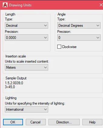
- 1. Type UN and set the units as Decimal and precision as 0.00
- 2. Set the units as Meter in the insertion scale
- 3. Type Limits in the command box and set the Lower limit as 0,0 and the Upper limit as 100,100
- 4. Type Z enter for Zoom Enter and A Enter for Zoom all
ÂÂ
Step 3:
- 1. Go to the Top view using the UCS icon at the top right corner
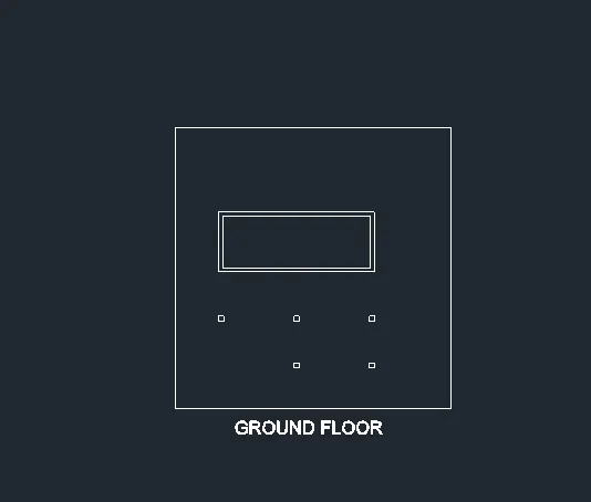
- 2. First we have to draw the floor plans of the G+2 residential building
- 3. Select the Rectangle tool by typing REC or Rectangle in the command box
- 4. Draw an outer boundary of the plot area with the dimension of 20 m*20 m
- 5.Hear I make the parking place for the ground floor having square column of size .4 m .
ÂÂ
ÂÂ
ÂÂ
Step 4:
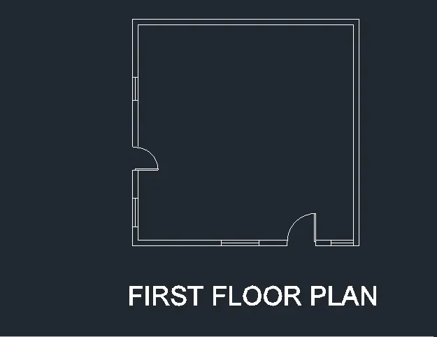
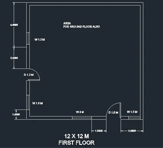
- 1.We have to sketch the first-floor plan
- 2. Then draw the Exterior wall with a thickness of .3m
- 3. For Interior walls, consider the thickness as .2m
- 4. Draw the First floor plan of the building using Line, Offset, Trim, and other tools
- 5. Provide the windows in the ground floor plan with the width of 1.2m and 2m,1.5m,1.2 mrespectively
- 6. Similarly, Provide the doors in the ground floor plan with a width of 1.5m &1.2 m respectively.
- 7. Draw a Staircase with the width of rise as 150mm and tread as 250mm
- 8. Provide the number of flights as 20, to create the staircase model in the floor plan.
- 9. Complete the First floor plan of the residential building using various other tools.
- 10.Hear I just draw the outer section of the Floor plan for creating the 3D project.
ÂÂ
ÂÂ
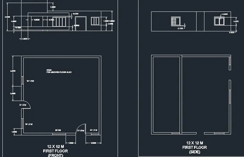
FIRST FLOOR DETAIL FOR THE 3D MODELING:-
ÂÂ
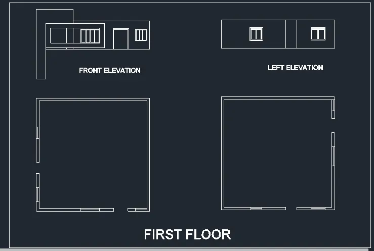
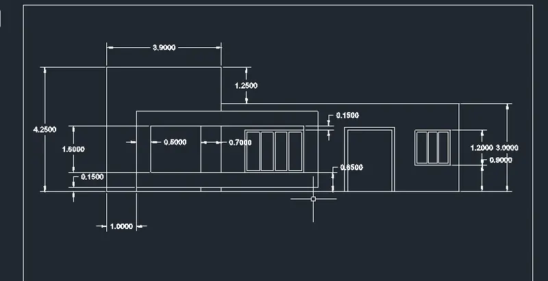
FLOOR DIMENSSION DETAIL :-
ÂÂ
FIRST FLOOR FRONT VIEW DIMENSSION DETAIL
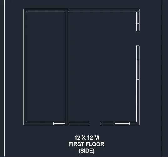
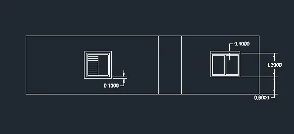
FIRST FLOOR SIDE DETAIL :-
ÂÂ
ÂÂ
DIMENSSION DETAIL FOR CREATING THE 3D VIEW:-
ÂÂ
ÂÂ
Step 5:
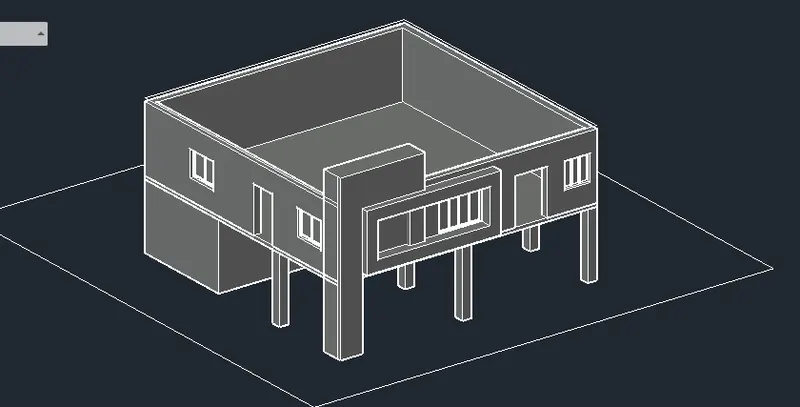
- Draw the ground floor with the first floor 3D modeling by using the above dimenssion detail .
- Now we have to give the boundaries to the walls of the first floor plan to create the regions inside it
- Select the Boundary tool by typing BO or Boundary in the command box
- Select the walls that we want to create the region excluding windows and doors. Then press Enter
- The region has been created successfully in the walls
- After creating the region, now we have to Extrude the walls
- Select the Extrude tool by typing EXT or Extrude in the command box
- Select all the walls that we created the regions earlier
- Then Extrude the walls with a height of 3m.
- Now we have to Extrude the windows and doors
- Select the Rectangle tool by typing REC or Rectangle in the command box
- Draw rectangles at each window portion to Extrude
- Select the Extrude tool and extrude all the rectangles to a height of 0.9m
- Select the Copy tool and Copy the Extruded rectangular portion to the top surface connecting the walls
- Similarly do the same process for the doors
- Select the Union tool by typing Union in the command box
- Select the extruded walls, windows, and doors.
- Then press enter to form a union of the ground floor plan
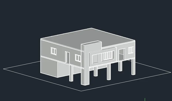
- Click The BOX command to creat the roof of the first floor.
ÂÂ
ÂÂ
Step 6:
- 1. Similarly, we have to sketch the first-floor plan with the ground-floor specifications
- 2. Separate the Rooms according to the requirement
- 3. Leave the space for the Sit-out area in the first-floor plan
- 4. Provide necessary Windows, Doors, and Ventilators at the desired location
- 5. Complete the First-floor plan as per the specifications and requirements
ÂÂ
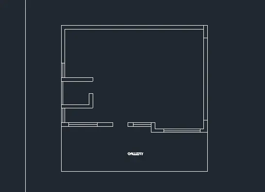
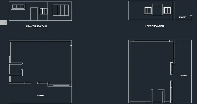
SECOND FLOOR PLAN VIEW :-
ÂÂ
SECOND FLOOR DETAIL FOR THE 3D MODELING:-
ÂÂ
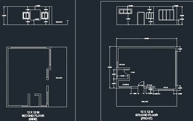
FLOOR DIMENSSION DETAIL :-
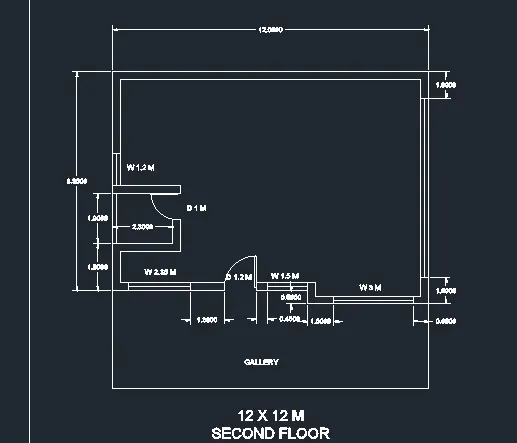
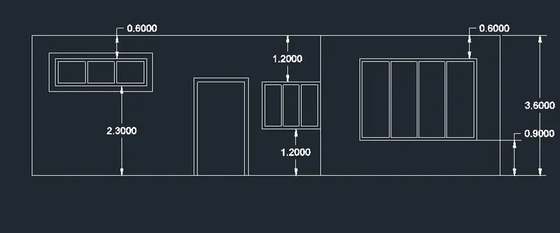
SECOND FLOOR FRONT VIEW DIMENSSION DETAIL
ÂÂ
ÂÂ
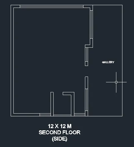
SECOND FLOOR SIDE ELEVATION DETAIL :-
ÂÂ
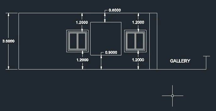
DIMENSSION DETAIL FOR CREATING THE 3D VIEW:-
ÂÂ
Step 7:
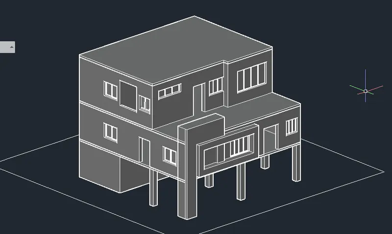
- Draw the Second floor with the first floor 3D modeling by using the above dimenssion detail .
- Now we have to give the boundaries to the walls of the secand floor plan to create the regions inside it
- Select the Boundary tool by typing BO or Boundary in the command box
- Select the walls that we want to create the region excluding windows and doors. Then press Enter
- The region has been created successfully in the walls
- After creating the region, now we have to Extrude the walls
- Select the Extrude tool by typing EXT or Extrude in the command box
- Select all the walls that we created the regions earlier
- Then Extrude the walls with a height of 3m.
- Now we have to Extrude the windows and doors
- Select the Rectangle tool by typing REC or Rectangle in the command box
- Draw rectangles at each window portion to Extrude
- Select the Extrude tool and extrude all the rectangles to a height of 0.9m
- Select the Copy tool and Copy the Extruded rectangular portion to the top surface connecting the walls
- Similarly do the same process for the doors
- Select the Union tool by typing Union in the command box
- Select the extruded walls, windows, and doors.
- Then press enter to form a union of the ground floor plan
ÂÂ
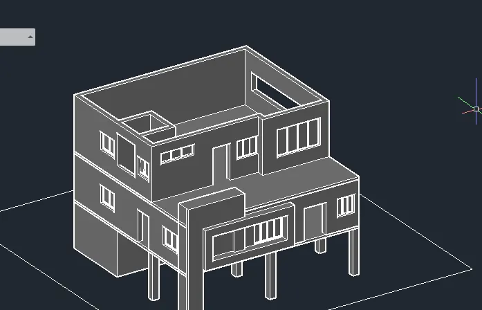
- Click The BOX command to creat the roof of the Second floor and make it as a single object by using the command Union.ÂÂ
ÂÂ
Step 8:-ÂÂ
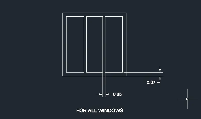
- Now we have to create the Windows with the help of the rectangle tool
- Go to the Top view using the UCS icon at the top right corner
- Select the Rectangle tool and draw a rectangle with appropriat length .
- Select the Offset tool and give the offset distance as 50mm
- Offset the rectangle through the inside as shown in the figure below
- Now draw a line at the center of the interior rectangle
- Now Offset the interior rectangle again with the offset distance of 30mm
- Select the interior rectangle in the left portion and copy it into the right portion
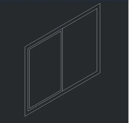
ÂÂ
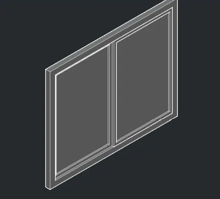
- Select the Prespull Tool by typing PR or Prespull in the command box
- Select the Exterior Rectangle portion and prespull it with a depth of 50mm
- Now, select the Interior rectangle and Prespull it with a depth of 30mm
- Again select the glass portion of the window and prespull it with a depth of 10mm
- The Window has been created with the panel, mullion, and glass section
ÂÂ
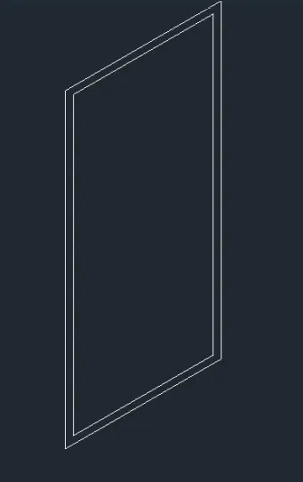
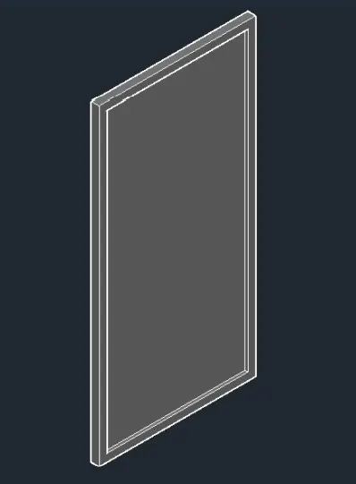
- Now we have to create the doors with the help of the rectangle tool
- Go to the Top view using the UCS icon at the top right corner
- Select the Rectangle tool and draw a rectangle with a appropriate length
- Select the Offset tool and give the offset distance as 100mm
- Offset the rectangle through the inside as shown in the figure below
ÂÂ
- Select the Prespull Tool by typing PR or Prespull in the command box
- Select the Exterior Rectangle portion and prespull it with a depth of 50mm
- Now, select the Interior rectangle and Prespull it with a depth of 30mm
- The Door and the frame have been created successfully
ÂÂ
ÂÂ
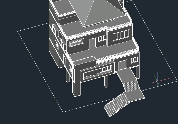
- After Creating the doors and windows, now we have to place them in the desired locations
- Select the Copy tool by typing CO or Copy in the command box
- Select the window and pick a point at the mid point of the below panel
- Now, move the copied window to the desired location as shown in the figure below
- Similarly, Select the door and pick a point at the mid-point of the below panel
- Now, move the copied door and panel to the desired location as shown in the figure below
ÂÂ
Step 8:-ÂÂ
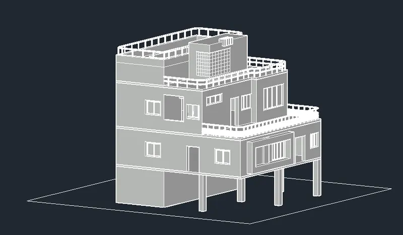
- Now we have to sketch the Headroom on the first floor
- Select the Rectangle tool by typing REC or Rectangle in the command box
- Sketch the headroom portion on the first-floor plan
- Select the Sketched rectangle and Extrude it to a height of headroom 2.5m.
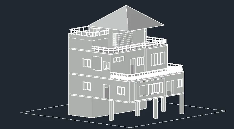
- Then sketch the roof on top of the headroom.
ÂÂ
Step 10:-ÂÂ
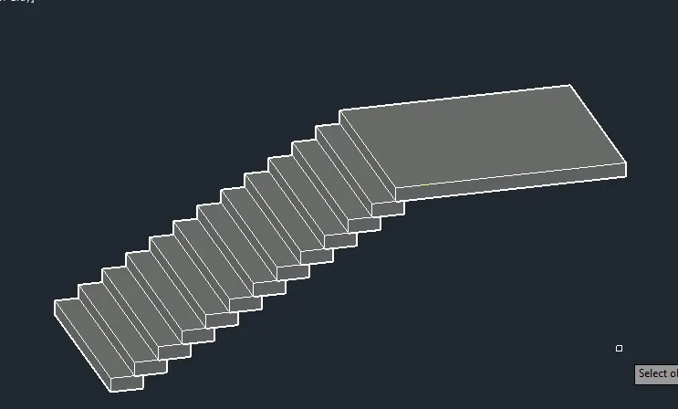
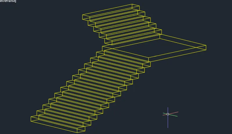
-  Now we have to sketch the staircase for the residential building
- Go to the Top view using the UCS icon at the top right corner
- Select the BOX tool .
- Draw a BOX (tread)of width .4m and the tread of the length of 250mme the rise of the height of 0.175 m.
- we draw total 18 step as per my calculation.
- Select the Copy tool and copy the rise and tread lines to form a section
- Similarly create the landing with a prespull the section length 2.5 m.
ÂÂ
ÂÂ
ÂÂ
ÂÂ
ÂÂ
Step 11:-ÂÂ
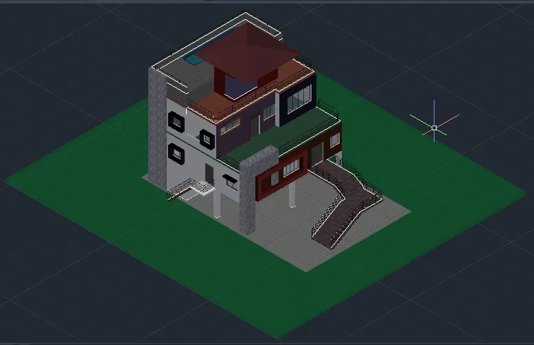
- After sketching the residential building unit, now we have to apply the material
- Open Material Browser by typing MAT in the command box
- In the Left corner, Expand the Autodesk library option
- Select the material that we want to apply to the sketch
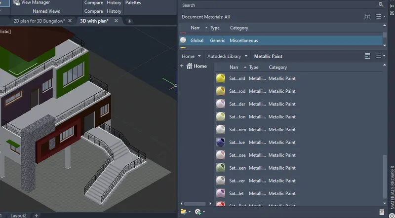
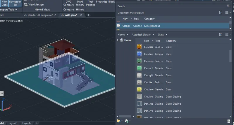
- After assigning the materials to the building, now we have to create the topographic ground surface
- Select the Box tool from the ribbon tab or by typing Box in the command box
- Create the box section with the dimensions and thickness as per the requirement
- Go to the Material Browser again and assign the Grass material to the ground surface
ÂÂ
ÂÂ
Step 12:-ÂÂ
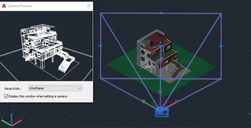
- Now we have to set the Camera for the rendering process
- Now go to visualise tab and select the camera tool from the render option
- Place the Camera on the Extruded circle to fix the position of the camera
- Adjust the target and focus on the residential building, then delete the extruded circle
ÂÂ
ÂÂ
Step 13:-ÂÂ
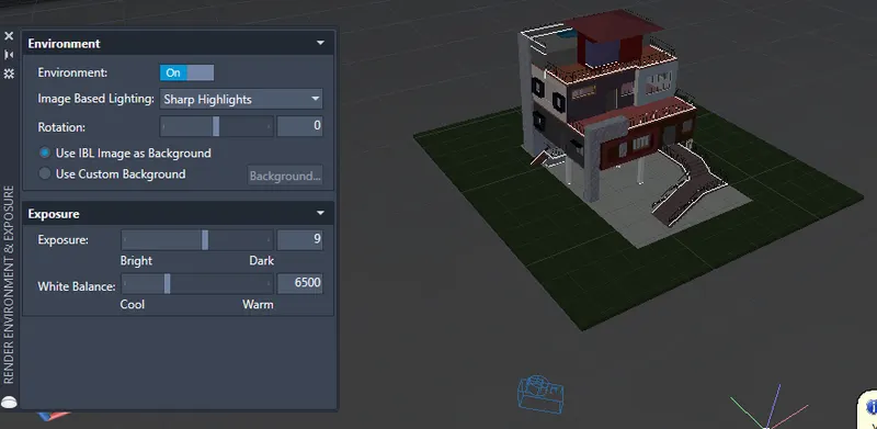
- Now we have to render the camera view with the advanced exposed conditions
- Select the Render drop-down tab from the visualise tab
- Set the Render environment and exposure according to the requirement
- Select the Sky On and Full Clouds option from the visualise tab
- Adjust the rendering settings manually according to the requirement
ÂÂ
Step 14:-ÂÂ
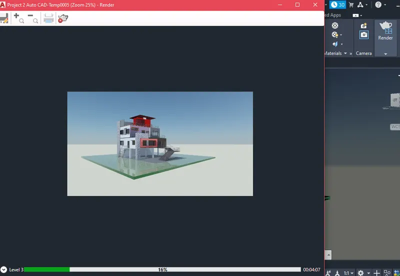
- After adjusting the rendering settings and exposure, go to the visualise tab
- Select the Render option from the visualise tab and click ok to render
- After clicking the render option, a rendering dialog box will open showing the status and preview of the rendering
- The 3D model of the Residential building has been rendered with various rendering views
 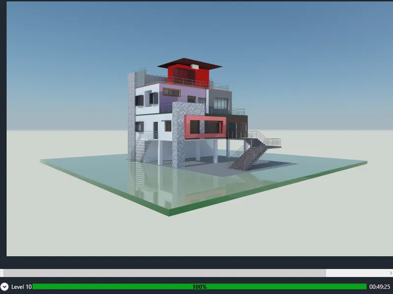
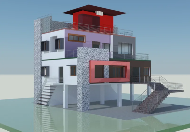
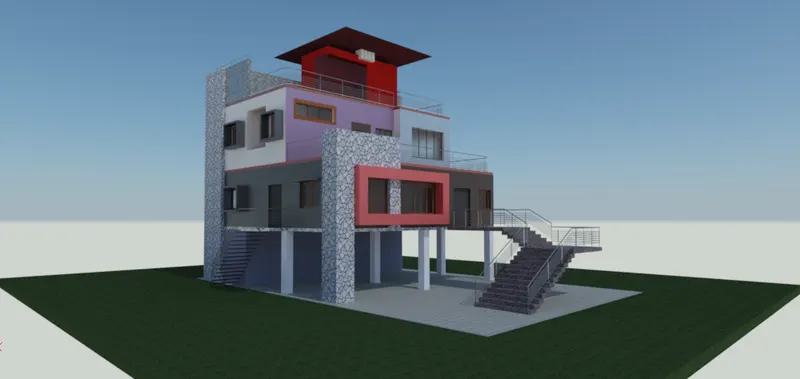
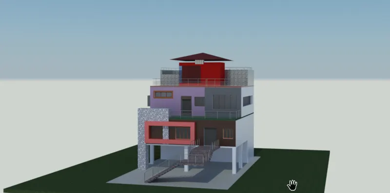
ÂÂ
ÂÂ