Structural Modelling using Etabs 2018
Aim:
To create the most feasible structural framing plan with all seismic requirements from the given architectural drawing. and to model the framing plan into G+7 building using ETABS.
Preparation on framing plan & Modelling with ETABS:
Step-1:
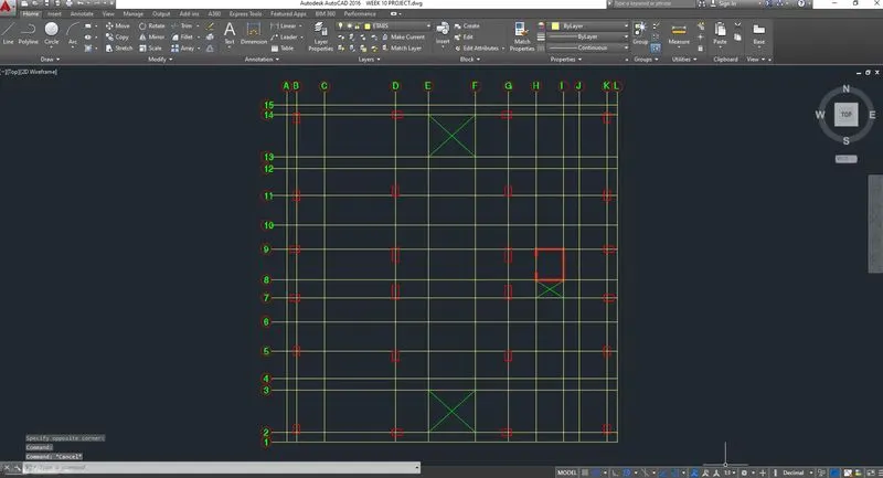
Based on the given architectural drawing, the probable column sizes and beam sizes and slab sizes and RC wall locations are selected.
Step-2:
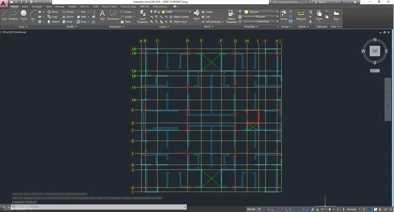
Required grid arrangements are marked and beam layout is drawn based on room occupancy.
Step-3:
New > User defined code and Material > Indian, IS456 for concrete, IS800 for steel
Edit storey data > customise storey heights
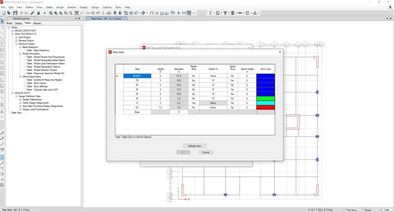
Using the above tools, the required code and mterials are selected. And storey is considered 1.5 meter for base and 3 meter for G+7 floors. additionally as mentioned by question, one more level created for Mumty.
Step-4:
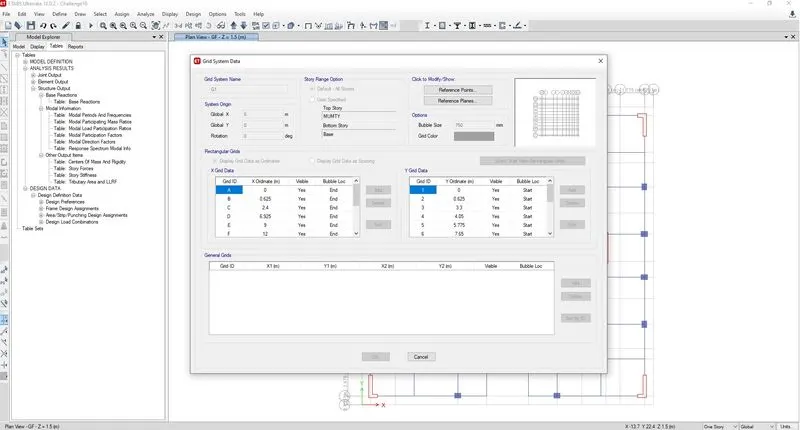
Using edit grid data, the necessary grids in both horizontal and vertical have been created.
Step-5:
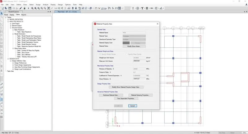
Define > Material
Concrete grade M25 is assigned.
Step-6:
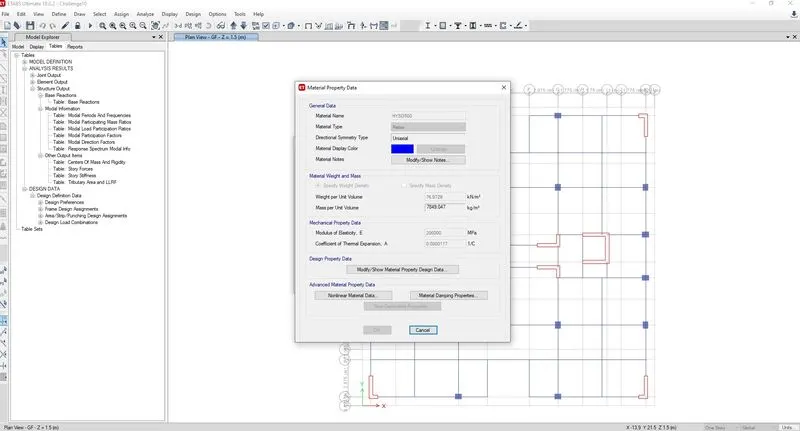
Define > Material
Rebar grade Fe500 is assigned for flexural design and Rebar grade Fe415 is assigned for shear design.
Step-7:
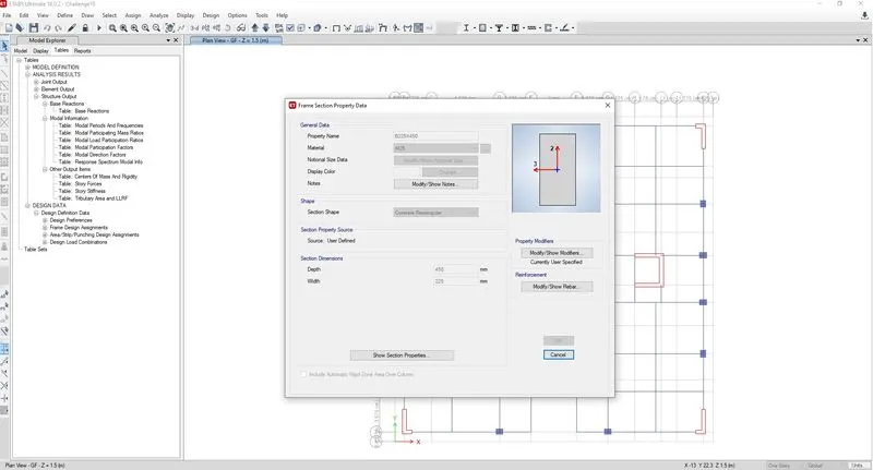
Define > Section properties > Frame sections
Initial beam size 225x450 is assigned.
Step-8:
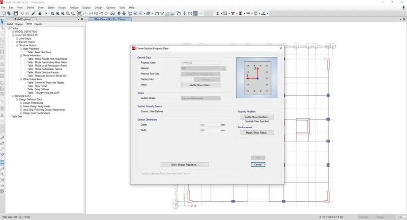
Define > Section properties > Frame sections
Two different column sizes are created, one for exterior columns and another for interior columns.
Step-9:
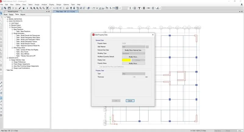
Define > Section properties > Slab sections
Two different slab sections are created, one for floor slabs (125mm) another for staircase waist slabs (150mm) with oneway load distribution condition.
Step-10:
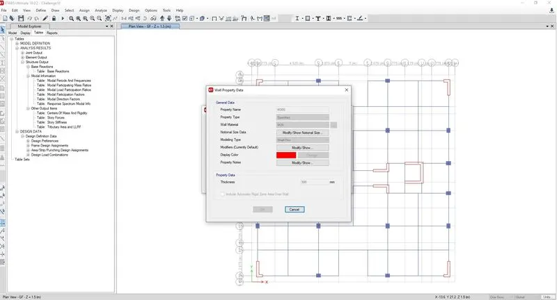
Define > Section properties > wall sections
Structural wall thickness 300mm is created for seismic load resisting purpose.
Step-11:
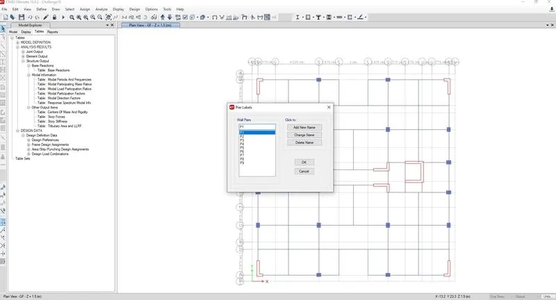
Define > Pier lables
As per framing plan, there would be 10 numbers of Structural walls. So pier names from 1 to 10 are created.
Step-12:
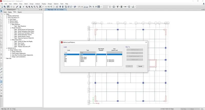
Define > Load patterns
Since the question provided floor finish and wall material, separate load cases for floorfinish and wall are created. dead load case for selfweight, live load (2 KN/sq.m) as reference to IS875 part-2, and Earthquake cases EQx, and EQy (assigning IS1893-2016) are created.
Step-13:
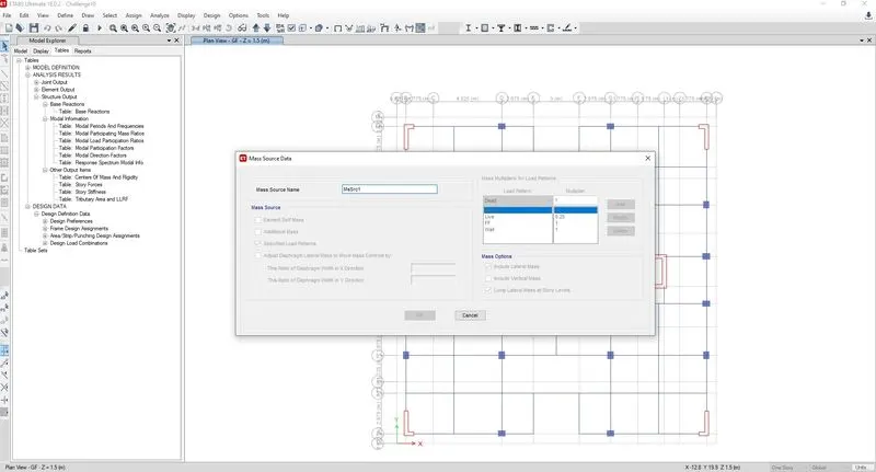
Define > Mass source > Modify
Using above toolpath, the load case participation factors are modified. As per IS1893-2016 code, live load factor 0.25 is assigned.
Step-14:
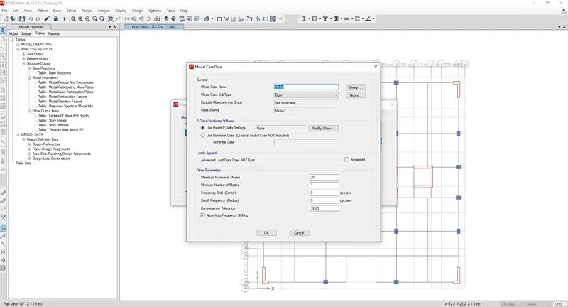
Define > Modal case
For seismic modal case, the maximum number of modes are revised as 20.
Step-15:
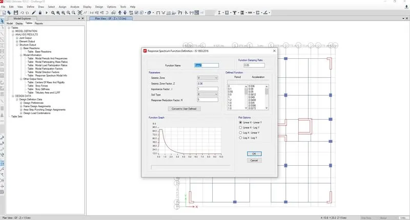
Define > Functions > Response spectrum > Add new function
Using above toolpath, mathematical function of response spectrum method is created with zone-5 base.
Step-16:
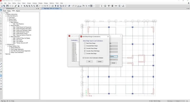
Define > Load combinations > Add Default design combos
Using above toolpath, default design combinations for concrete frame design + concrete wall design are created.
Step-17:
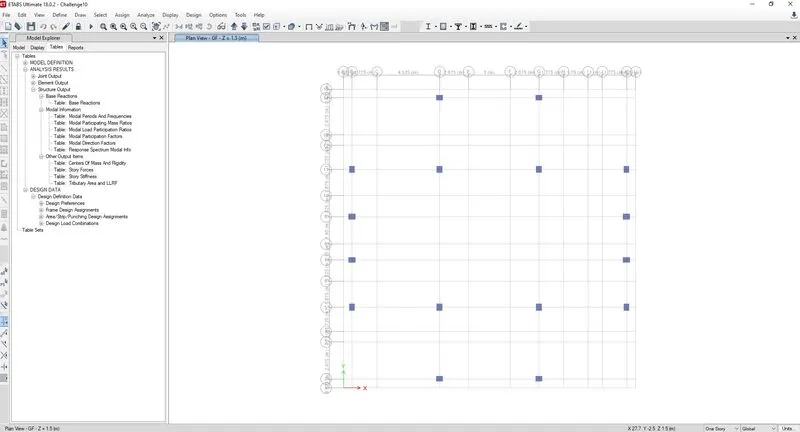
Columns are drawn using quick draw column option for all storeys.
Step-18:
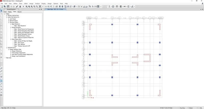
Structural walls are drawn with intial locations and at corewall locations. Area of floor is nearly 20 meter x 20 meter = 400 sq.m
The assumed RC walls covers 19.1 meter length in total, which will give 5.75 sq.m area for RC wall. the ratio of RC wall area to floor area is,
5.75/400 = 1.45%.
Step-19:
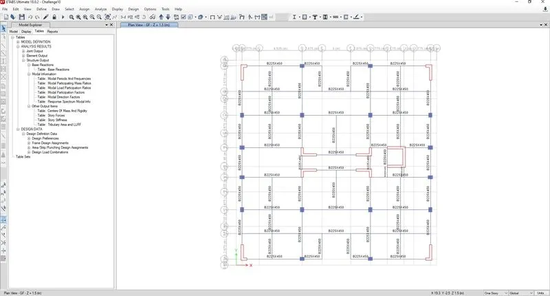
Beams are drawn using quick draw beams option for all storeys.
Step-20:
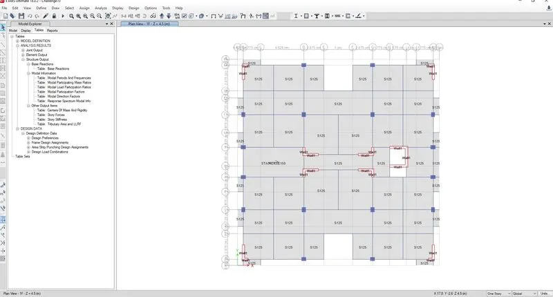
Using rectangular slab drawing option, slab 125mm section is drawn with similar storeys option.
Step-21:
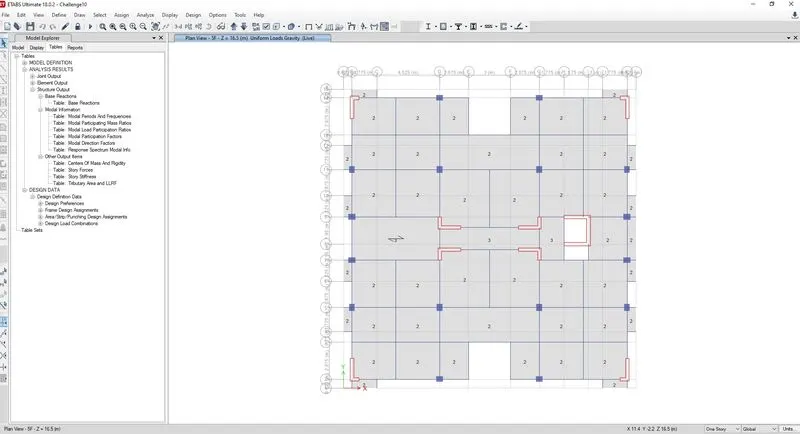
live loads as suggested by IS875 part-2, are assigned for all floors. Terrace floor live load is assigned as .5 sq.m
Step-22:
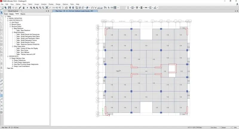
75mm floor finish is given, So density of cement mortar 20 kN/cu.m x 0.075m = 1.5 kN/sq.m
The floor finish is assigned for all floors.
Step-23:
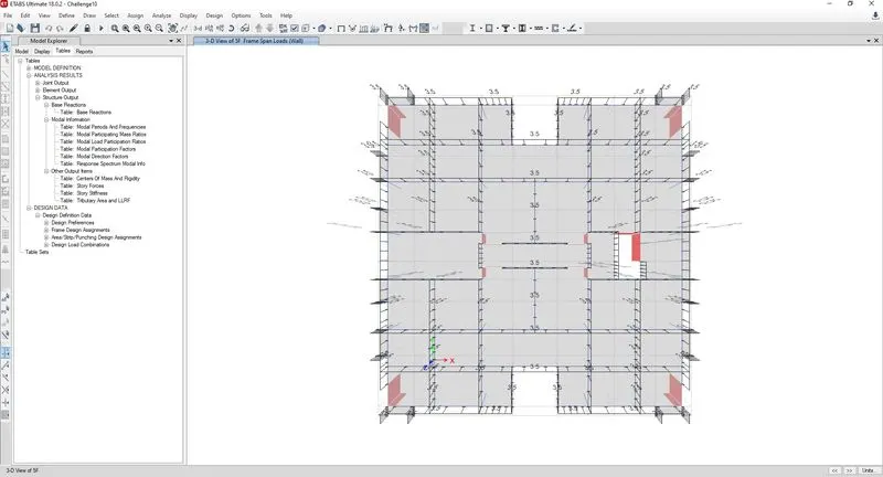
Partitiona wall material is provided as AAC block, so AAC density 6.5 kN/cu.m x 0.2 m thickness x 2.55 m height = 3.3 kN/meter
So rounding it off to 3.5 kN/m line load is assigned to all RC beams.
Step-24:
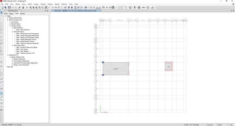
Above the terrace floor, one more floor is created for mumty level. There water tank load and lift machine loads are assumed and assigned
Step-25:
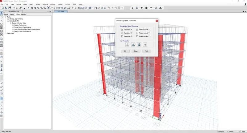
At base level, all joints are assigned as fixed suport.
Step-26:
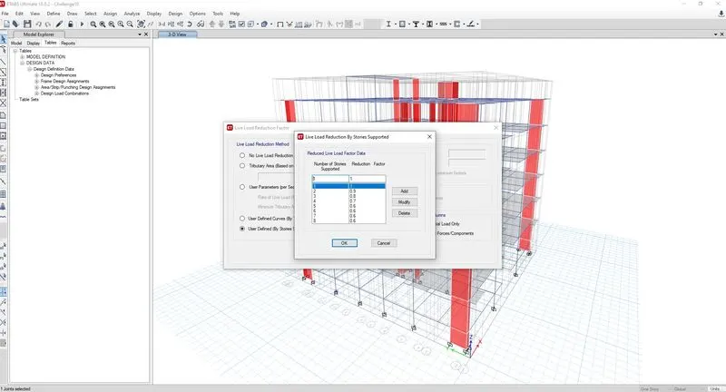
Design > Liveload reduction factor
Using above toolpath, live load factors are provided with reference to IS 875 part-2 table.
Step-27:
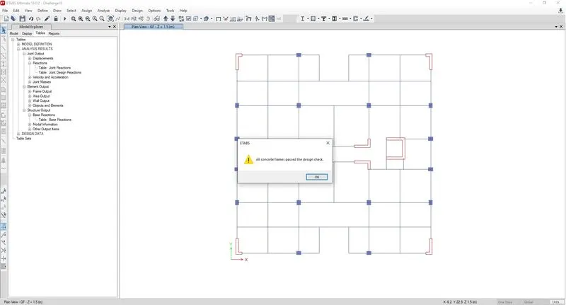
Analyse > Run analysis
Design > Concrete frame design > Start design check
Design > Concrete slab design > start design check
Using above toolpath, the ETABS model is analysed and designed for seismic forces. And verified all the frame members passing the design.
Step-28:
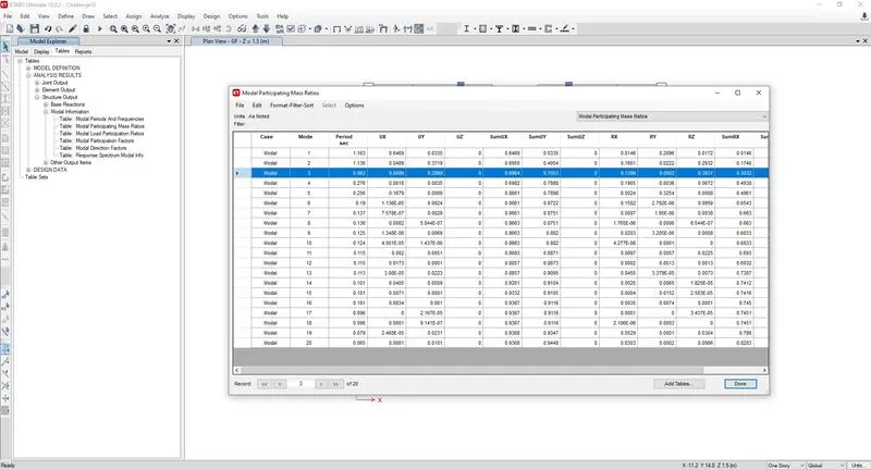
Display > Tables > Analysis results > Structure output > Modal information > Modal mass participation ratios
Using above toolpath, the fundamental modal mass are viewed. It is ensured that first two fundamental modes are greater than the torsional mode.
Step-29:
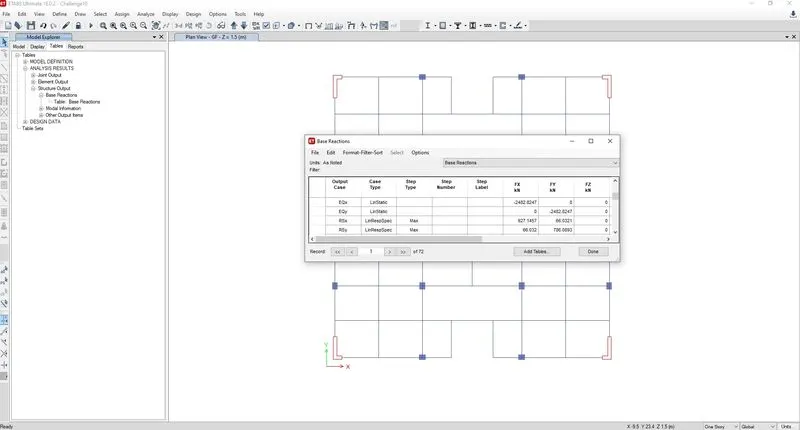
Display > Tables > Analysis results > Structure output > Base reactions
Using above toolpath, the base reactions at base level for earthquake case are checked. Keeping EQx and EQy are minimum seismic forces as per IS 1893-2016, the scale factor for Spectrum response forces are calculated.
Step-30:
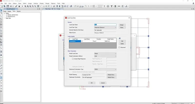
Based on the scale factor arrived by dividing the EQx/RSx, the factor is modified from Define > Function > Response spectrum > Modify toolpath. Now the structure is reanalysed and checked. It is noted that EQx is almost same as RSx.
Since the purpose of EQx is over, the load case is removed from Load patterns and load combinations.
Step-31:
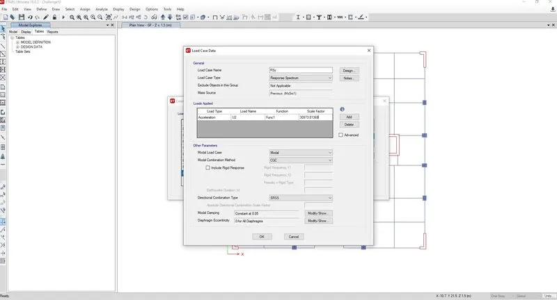
Based on the scale factor arrived by dividing the EQy/RSy, the factor is modified from Define > Function > Response spectrum > Modify toolpath. Now the structure is reanalysed and checked. It is noted that EQy is almost same as RSy.
Since the purpose of EQy is over, the load case is removed from Load patterns and load combinations.
Step-32:
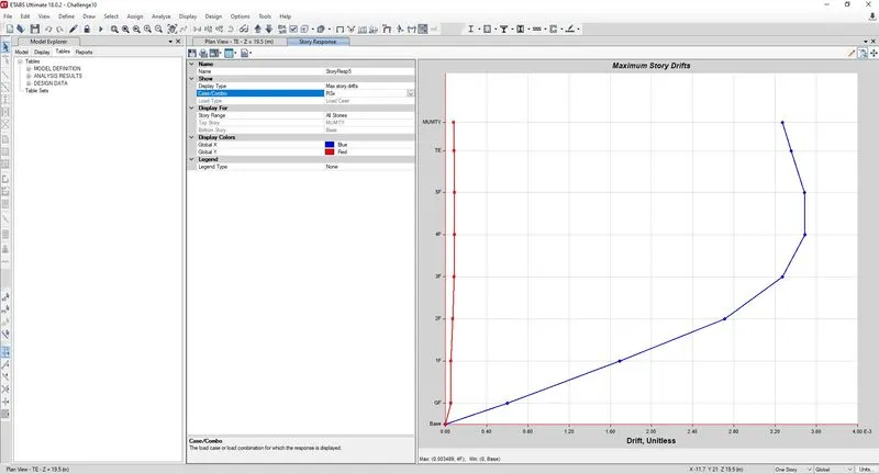
Display > Storey response plot > Inter storey drift (RSx)
Using the above toolpath, the inter storey drifts are checked for RSx case. the values are within 0.004 as suggested by IS 1893-2016.
Step-33:
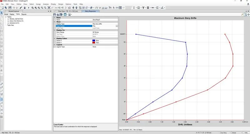
Display > Storey response plot > Inter storey drift (RSy)
Using the above toolpath, the inter storey drifts are checked for RSx case. the values are within 0.004 as suggested by IS 1893-2016.
Step-34:
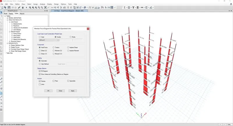
Display > Force/Stress diagrams > Frame/Pier/Spandrel forces
Using the above toolpath, the base forces for columns are ensured only with compressive forces in all combinations.
Step-35:
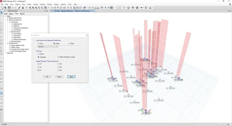
Display > Force/Stress diagrams > Shell stresses/Force
Using the above toolpath, the base compressive stresses for RC walls are ensured within concrete compressive limit (0.28 Fck) in all combinations.
Step-36:
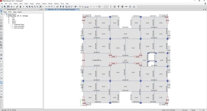
After number of iterations, the final structural arrangement is arrived as shiwn above.
Attachment:
The final ETABS model is attached along with the challenge.
Conclusion:
Thus as required by the question, the structural framing plan and ETABS modelling is done with seismic force assignment. Also the necessary seismic criteria is verified for all lateral members of ETABS model.