MATLAB Program based on Air Standard Cycle
AIM :
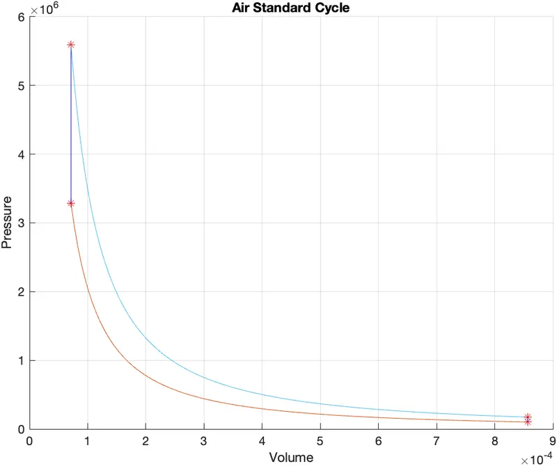
To write a MATLAB program to solve an otto cycle and make plots for it.
OBJECTIVES :
- To create a PV diagram.
- To find out the thermal efficiency of an engine.
THEORY :
The Otto cycle is one of the most common thermodynamic cycles found in automobile engines. One of the key parameters of such an engine is the change in volume from the top dead centre (TDC) to the bottom dead centre (BDC). The ratio of these volumes `[(v1)/(v2)]` is known as the compression ratio.
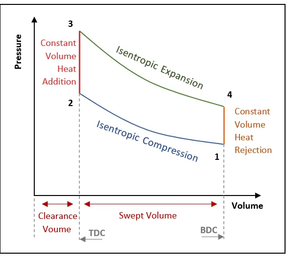
The processes are described by:
- Process 0–1 : Mass of air is drawn into piston/cylinder arrangement at constant pressure.
- Process 1–2 : It is an adiabatic (isentropic) compression of the charge as the piston moves from the bottom dead centre (BDC) to the top dead centre (TDC).
- Process 2–3 : It is a constant-volume heat transfer to the working gas from an external source while the piston is at the top dead centre. This process is intended to represent the ignition of the fuel-air mixture and the subsequent rapid burning.
- Process 3–4 : It is an adiabatic (isentropic) expansion (power stroke).
- Process 4–1 : It completes the cycle by a constant-volume process in which heat is rejected from the air while the piston is at the bottom dead centre.
- Process 1–0 : Mass of air is released into the atmosphere in a constant pressure process.
FORMULA :
`[ v / v_c ] = 1 + ( 1 /2 ) ( c r − 1 ) [ R + 1 − cos θ − ( R^ 2 − ( sin θ )^ 2 )^( 1/2) ]`
Terms used during this MATLAB Program
v = volume
v_s = swept volume
v_c = clearance volume
t = temperature
p = pressure
cr = compression ratio
R = ratio of connecting rod length to the crankpin radius
a = crankpin radius
PROGRAM :
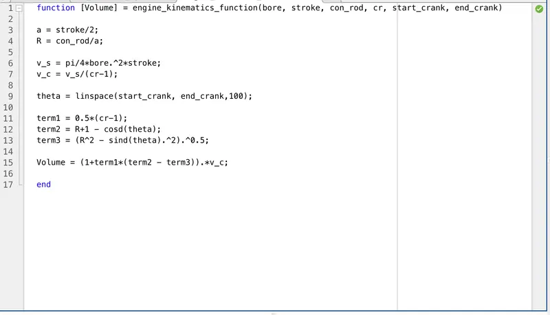
FUNCTION -
function [Volume] = engine_kinematics_function(bore, stroke, con_rod, cr, start_crank, end_crank)
a = stroke/2;
R = con_rod/a;
v_s = pi/4*bore.^2*stroke;
v_c = v_s/(cr-1);
theta = linspace(start_crank, end_crank,100);
term1 = 0.5*(cr-1);
term2 = R+1 - cosd(theta);
term3 = (R^2 - sind(theta).^2).^0.5;
Volume = (1+term1*(term2 - term3)).*v_c;
end
FINAL PROGRAM -
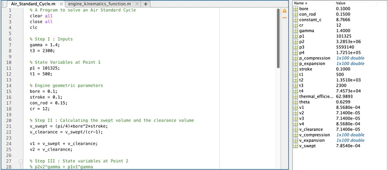
% A Program to solve an Air Standard Cycle
clear all
close all
clc
% Step I : Inputs
gamma = 1.4;
t3 = 2300;
% State Variables at Point 1
p1 = 101325;
t1 = 500;
% Engine geometric parameters
bore = 0.1;
stroke = 0.1;
con_rod = 0.15;
cr = 12;
% Step II : Calculating the swept volume and the clearance volume
v_swept = (pi/4)*bore^2*stroke;
v_clearance = v_swept/(cr-1);
v1 = v_swept + v_clearance;
v2 = v_clearance;
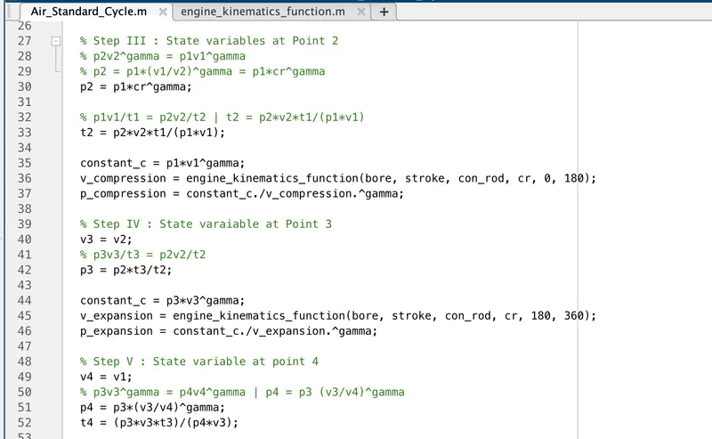
% Step III : State variables at Point 2
% p2v2^gamma = p1v1^gamma
% p2 = p1*(v1/v2)^gamma = p1*cr^gamma
p2 = p1*cr^gamma;
% p1v1/t1 = p2v2/t2 | t2 = p2*v2*t1/(p1*v1)
t2 = p2*v2*t1/(p1*v1);
constant_c = p1*v1^gamma;
v_compression = engine_kinematics_function(bore, stroke, con_rod, cr, 0, 180);
p_compression = constant_c./v_compression.^gamma;
% Step IV : State varaiable at Point 3
v3 = v2;
% p3v3/t3 = p2v2/t2
p3 = p2*t3/t2;
constant_c = p3*v3^gamma;
v_expansion = engine_kinematics_function(bore, stroke, con_rod, cr, 180, 360);
p_expansion = constant_c./v_expansion.^gamma;
% Step V : State variable at point 4
v4 = v1;
% p3v3^gamma = p4v4^gamma | p4 = p3 (v3/v4)^gamma
p4 = p3*(v3/v4)^gamma;
t4 = (p3*v3*t3)/(p4*v3);
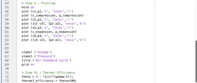
% Step V : Plotting
hold on
plot (v1,p1, '*', 'Color', 'r')
plot (v_compression, p_compression)
plot (v2,p2, '*', 'Color', 'r')
plot ([v2 v3], [p2 p3], 'color', 'b')
plot (v3,p3, '*', 'Color', 'r')
plot (v_expansion, p_expansion)
plot (v4,p4, '*', 'Color', 'r')
plot ([v4 v1], [p4 p1], 'color', 'b')
xlabel ('Volume')
ylabel ('Pressure')
title ('Air Standard Cycle')
grid on
% Step VI : Thermal Efficiency
thermal_efficiency = theta*100;
CONCLUSION :
Hence, the thermal efficiency of an engine and PV diagram for the Air Standard cycle is obtained with the help of the MATLAB program.