Exercise on Simulink Modeling
Que. 1
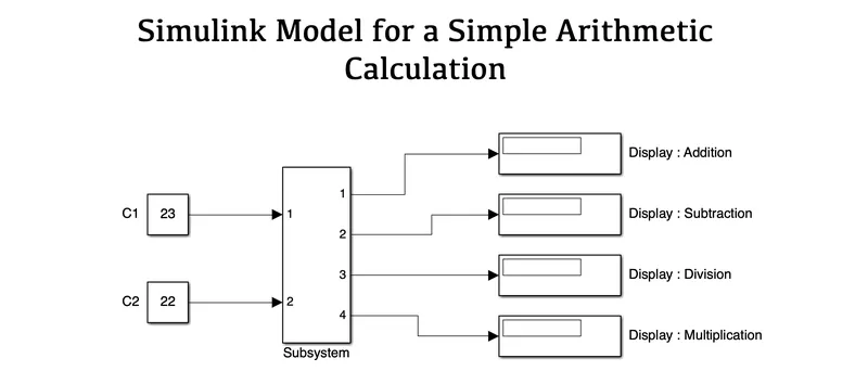
AIM: To create a Simulink model which performs simple arithmetic calculations.
OBJECTIVES :
- To perform simple arithmetic calculations such as add, subtract, multiply & divide.
SIMULINK MODEL :
SUBSYSTEM :
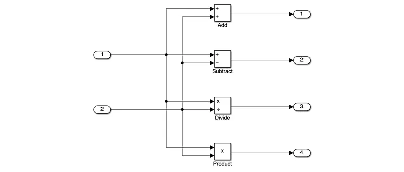
BLOCKS USED :
- Constants
- Subsystem
- Add
- Subtract
- Divide
- Product
- Display
EXPLANATION :
- To perform simple arithmetic calculations we first sorted out all the required blocks.
- The two constant blocks have different input values.
- These constant blocks are connected to ADD, SUBTRACT, DIVIDE and PRODUCT blocks to process the result and later converted into a Subsystem Block.
- The Subsystem blocks out were further connected to their respective Displays which shows the final arithmetic calculation.
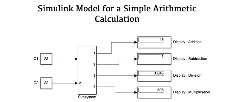
RESULTS :
CONCLUSION :
Hence we have created a Simulink model which performs all the simple arithmetic operations such as add, subtract, multiply and divide operations using the given inputs.
Que. 2
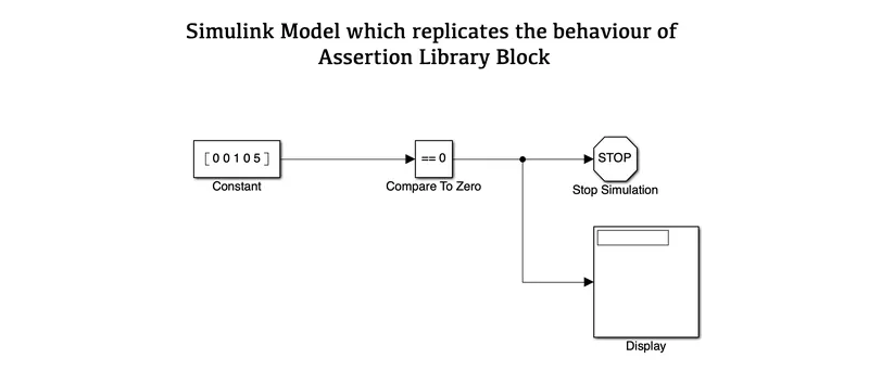
AIM: To create a Simulink model which will replicate the behaviour of Assertion Library Block.
OBJECTIVES :
- To replicate the behaviour of Assertion Library Block.
SIMULINK MODEL :
BLOCKS USED :
- Constant
- Compare to Zero
- Stop Simulation
- Display
EXPLANATION :
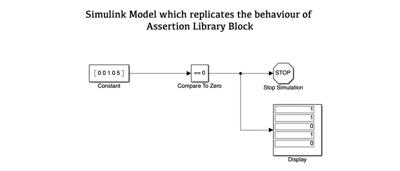
- To get similar behaviour we first sorted out all the required blocks.
- We took a Constant block having 5 elements in a single row.
- Next, we use a Comparision block which compares whether input elements were equal to zero or not.
- At Output, we have a Display and a Stop Simulation block.
- If the input is equal to zero then it will show the result as 1 stating that the comparison is true. If the input is non-zero then it will show the result as 0 stating that the comparison is false.
RESULTS :
CONCLUSION :
Hence we have created a Simulink model which replicates the behaviour like Assertion Library Block and gives the result in the form of 0's & 1's based on the comparison.
Que. 3
AIM: To design a Simulink model that allows Air Conditioners to operate dependent on the temperature of the room.
OBJECTIVES :
- To create a subsystem for an AC which will be enabled only by giving an input voltage of 5V.
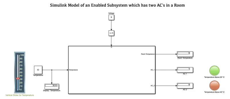
- When Room Temperature is greater than 30, 1 AC must be turned on.
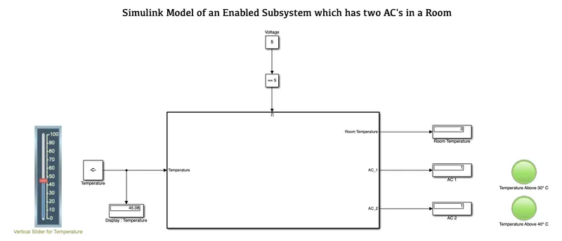
- When Room Temperature is greater than 40, both AC must be turned on.
SIMULINK MODEL :
ENABLED SUBSYSTEM :
BLOCKS USED :
- Input & Output Ports
- Enable Subsystem
- Relation Operators
- Vertical Sliders
- Constants
- Displays
- Lamps
EXPLANATION :
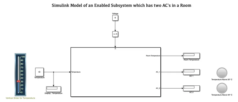
- For creating a Simulink model for an enabled subsystem that consists of two ACs, we first sorted out all the required blocks.
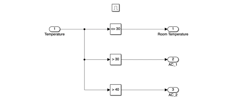
- We have one Input Port and three Output Ports for room temperature and AC respectively.
- Based on the conditions if the room temperature is greater than 30°C then the ACs must be turned ON/OFF.
- All these operations are controlled by an enabled system which will be enabled only on giving an input voltage of 5V.
- So we gave a relation operator to compare the voltage which needs to be equal to 5V.
- With Temperature as input, we connected it with a slider which gives us a variable temperature while sliding manually.
- At Output, we have three ports - Room Temperature, AC 1 and AC 2.
- When the temperature is greater than 30°C, then AC 1 will gets ON and the lamp colour will change to Green.
- When the temperature is greater than 40°C, then AC 1 will remain ON and AC 2 will gets ON and the lamp colour will change to Green.
- If the room temperature gets below 30°C, then both the ACs will be turned OFF simultaneously.
RESULTS :
1. Condition: Voltage == 5 at Room temperature less than 30. AC is in the OFF state.
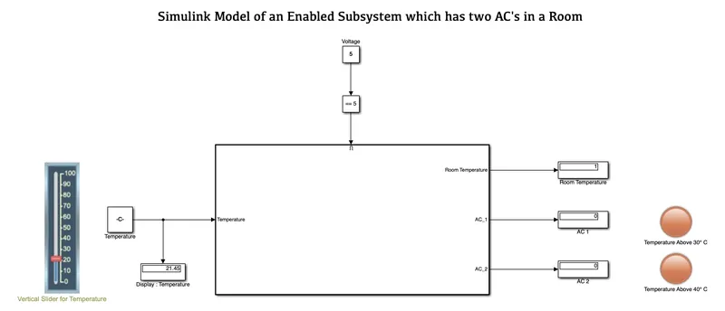
2. Condition: With Voltage == 5 and Room Temperature is greater than 30, AC 1 turns ON.
3. Condition: With Voltage == 5 and Room Temperature is greater than 40, both AC 1 and AC 2 turns ON.
CONCLUSION :
Hence we have created a Simulink model using an enabled subsystem that will Turn ON/OFF the AC based on the room temperature.
Que. 4
AIM: To design a Simulink model that allows light to be turned ON/OFF in a room based on luminous intensity.
OBJECTIVES :
- To create a subsystem for the light which will be enabled only by giving an input voltage of 5V.
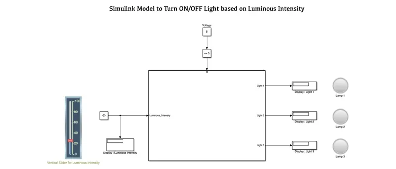
- To turn ON and OFF the required lights in a room based on luminous intensity.
SIMULINK MODEL :
ENABLED SUBSYSTEM :
BLOCKS USED :
- Input & Output Ports
- Relation Operators
- Enabled Subsystem
- Constants
- Displays
- Lamps
- Vertical Slider
EXPLANATION :
- To create a Simulink model which will turn ON/OFF the Lamps based on the Luminous Intensity, first we sorted out all the required blocks.
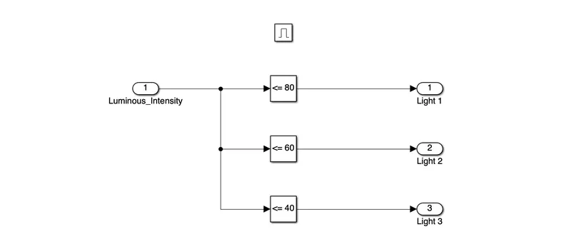
- Then based on the given condition we arranged Relation Operators so as to get the desired lamps turning ON as per the intensity. They are :
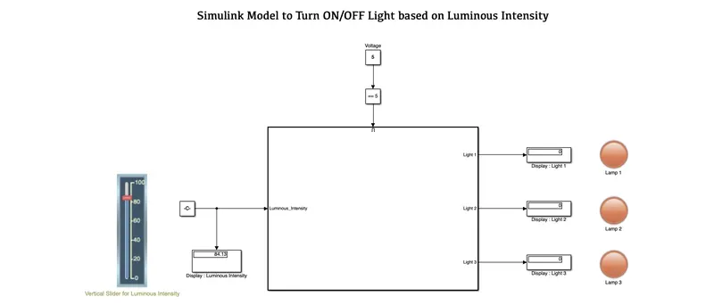
- If the luminous intensity is greater than 80 then all lamps will be in the OFF state.
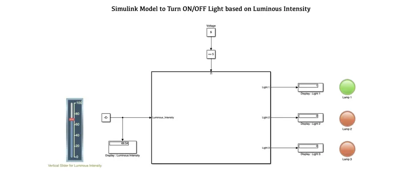
- If the luminous intensity is less than 80 then Lamp 1 turns ON.
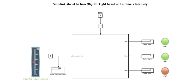
- If the luminous intensity is less than 60 then Lamp 1 and Lamp 2 turns ON.
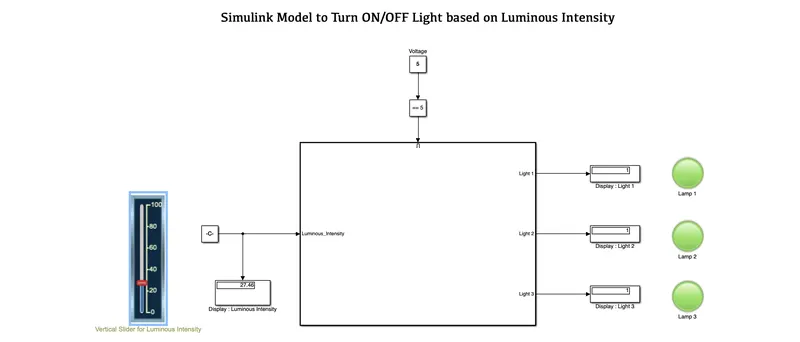
- If the luminous intensity is less than 4 then Lamp 1, Lamp 2 & Lamp 3 turns ON.
- All these operations are controlled by an enabled system which will be enabled only on giving an input voltage of 5V.
- Later this system is converted into a subsystem having Luminous Intensity at Input and Display at the Output.
- To get variable Luminous Intensity at input we have connected a vertical slider which is controlled manually.
- Based on the Intensity and conditions the result is shown in the display and accordingly Lamps Turns ON/OFF.
RESULTS :
1. Condition: Voltage == 5 and Luminous Intensity is greater than 80 then all Lamps are in OFF state.
2. Condition: Voltage == 5 and Luminous Intensity is in between 60 and 80, then Lamp 1 Turns ON.
3. Condition: Voltage == 5 and Luminous Intensity is in between 40 and 60, then Lamp 1 & Lamp 2 Turns ON.
4. Condition: Voltage == 5 and Luminous Intensity is less than 40, then Lamp 1, Lamp 2 & Lamp 3 Turns ON.
CONCLUSION :
Hence we have created a Simulink model using an enabled subsystem that will Turn ON/OFF the Lamps based on the Luminous Intensity.
Que. 5
AIM: To create a Simulink model to understand the behaviour of the saturation Simulink library block.
OBJECTIVES :
- To create a user-defined library of saturation custom blocks, add it to a Simulink model.
- To create a mask for the library block in the Simulink model.
SIMULINK MODEL :
SUBSYSTEM :
BLOCKS USED :
- Constants
- Input & Output Ports
- Relation Operators
- Logical Operator
- Switch
- Display
EXPLANATION :
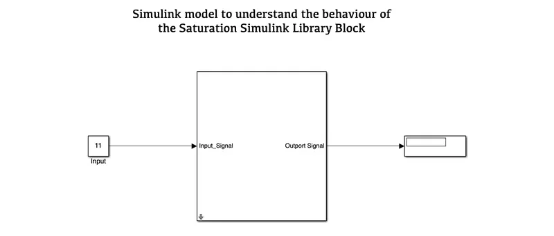
- To create a Saturation Simulink model which gives similar results, we first sorted out all the required blocks.
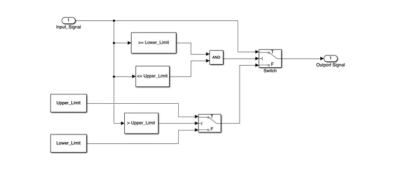
- Then created a library block that consists of a Subsystem.
- This Subsystem performs the logical as well as relation operation. It consists of an input port.
- These inputs were connected with relation operators based on the specified condition to give us the desired output.
- Once the system is ready, it is then converted into a Subsystem and later dragged or copy-paste to a Simulink Blank Model.
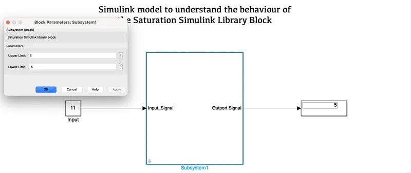
- In Simulink Blank Model this subsystem is then Masked with additional descriptions along with specified input parameters such as Upper_Limit and Lower_Limit.
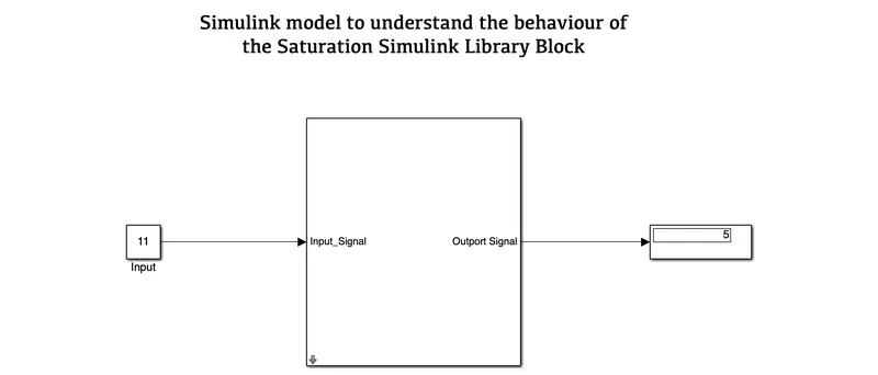
- Lastly, we connected all the required constants at input and display at the output.
RESULTS :
CONCLUSION :
Hence we have created a Simulink model which helps to understand the behaviour of the saturation Simulink library block.
Que. 6
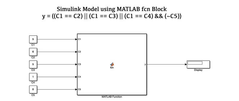
AIM: To create a MATLAB function block for the given logic using the MATLAB fcn library block.
OBJECTIVES :
- To create a MATLAB function block.
- To solve the logic using the MATLAB fcn library block.
SIMULINK MODEL :
FUNCTION :
function y = fcn(C1,C2,C3,C4,C5)

y = ((C1 == C2) || (C1 == C3) || (C1 == C4) && (~C5));
BLOCKS USED :
- Constants
- MATLAB Function (fcn)
- Display
EXPLANATION :
- First we sorted out all the required blocks to solve the logic operation.
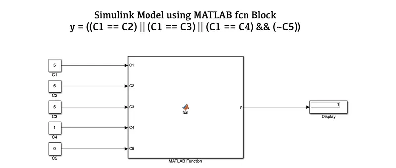
- Then we derive the values of Constant blocks (C1 = 5, C2 = 6, C3 = 5, C4 = 1, C5 = 0) as given.
- These blocks were connected to a MATLAB Function block which creates a function (fcn) that help to perform the logic operation. The logic used in the function were ==, ||, &&, ~.
- The output of the Function block is connected with a Display to get the final result.
RESULTS :
CONCLUSION :
From the above result, we have derived a MATLAB function for the given logic using the MATLAB library block.
Where, y = ((C1 == C2) || (C1 == C3) || (C1 == C4) && (~C5)) and its output is displayed.
- Mayur SalunkheThank you so much.