Hood design-Week 2
Submitted by: Syed Rizwan Ali
Course: Automotive sheet metal design using Seimens NX Cad
Challenge: Hood Design
Study Required: A detailed report about the Hood Design which includes a detailed explanation of the hood and its components, Latch Trajectory, Mastic Data, Emboss Definitions, Manufacturing processes like Deep-Drawing and Hemming, and all the parameters followed in the design.
What is Hood?
In simple words, we can say the hood is the cover of the engine in the front engine vehicle. Or very common word is car bonnet. Its purpose is to provide access to the engine for repair and maintenance. usually, hoods are made stylish and aerodynamic so that car can give luxurious look as well as reduce the air pressure during motion and keep the car on the ground.
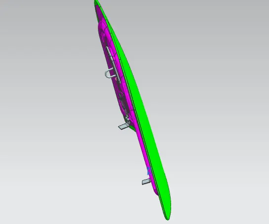
Hood designing and consideration with respect to safety and features:
The hood of a car is considered the frontal BIW enclosure component. Hood or bonnets are designed in such a way (Aerodynamically) that they can reduce air resistance as the air flows around the car.
Apart from this, hoods are also designed to meet several other requirements like a captive area for water storage if wiper and other features beneath it.
With respect to the safety of humans, they serve a great deal of purpose in protecting the passengers inside the car & the pedestrians in the event of an accident. It also acts as the cover for the engine. Illustration of hood sheet metal shape and angle used in design for safety purpose shown below-
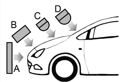
A: Lower legs
B: Upper legs waist and hip
C: Child body and head
D: Adult head
listed point indicates that the body of a human suffers less during impact.
The Euro NCAP (2015b) Safety Assessment Program includes a test protocol for pedestrian protection. The protocol covers lower leg, upper leg, and head impact tests shown as A, B, C, and D in Figure 3, along with a schematic explanation of the wrap-around distance (WAD)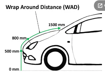
Following parts are used in hood assembly for this report,
1. Hood outer panel
2. Hood inner panel
3. Hinge assembly
4. Striker assembly
Supporting parts of hood are
5. Support rod
6. Gas stay
Given data are-
Hood thickness
Outer panel thickness=0.75 mm
Inner panel thickness=0.75 mm
Reinforcement thickness=1.5 mm
Master section-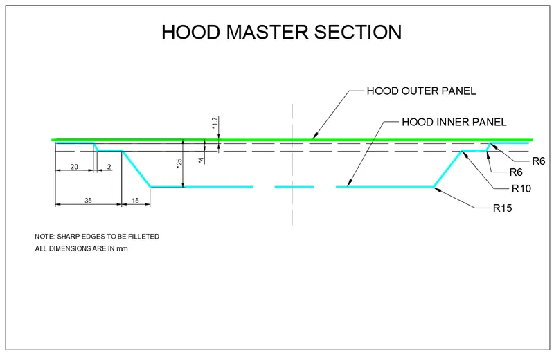
Inner Panel -
This part of the hood is known as the inner panel because is face the engine and rests below the upper part i.e outer panel of the hood (bonnet).
here we can do all the research related to safety measures of driver and passenger seating inside the vehicle. To provide reinforcement several features are added to the inner panel-
embossing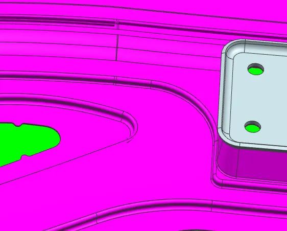
mastic point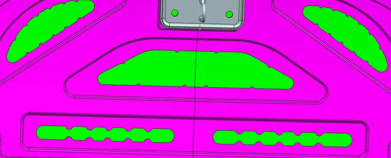
trim of sheet for strengthening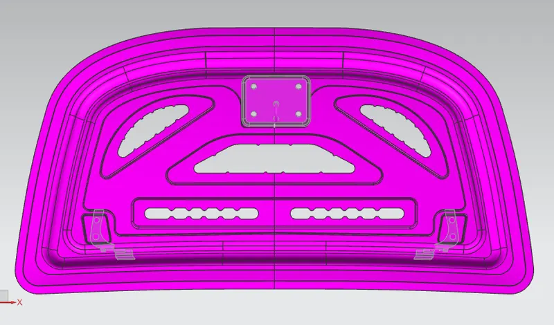
The features are attached to the inner panel to assure a sufficient amount of energy gets absorbed during a collision. deformation absorbs the impact and does not transmit it to the driver section.
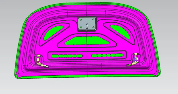
below is the inner panel made in NX cad
thickness = 0.75mm
Outer Panel -
The focus of the part is to make the car luxurious. Has an Aerodynamic body shape. The upper part oof the inner panel is usually known as the bonnet.
To avoid manufacture deforming and shape irregularities come due to joining processes such as welding or riveting, the outer and inner panels are joined or attached by using the method of hemming and deep drawing
Most of the time outer panels are taken from prototypes.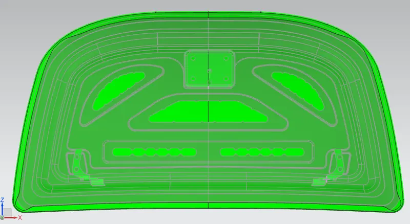
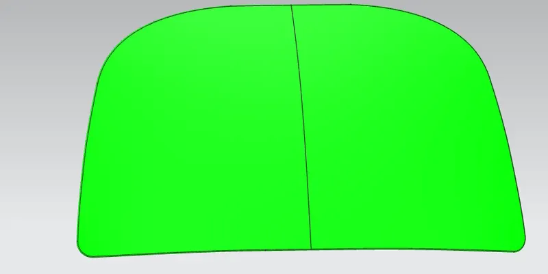
Reliefs providing in outer
panel for proper wrapping on the inner panel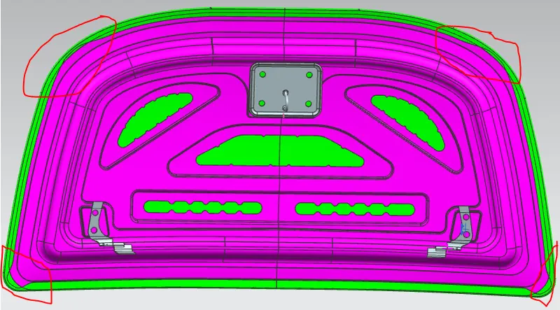
Thickness=0.75 mm
for wrapping spacing giving is 0.75+0.2+0.75+0.2+0.75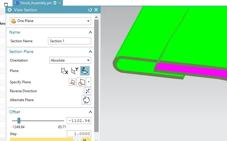
Hinge Assembly -
A hinge is a component that fixes the hood to the fenders of the car. The latch must be fixed perpendicular to the hinge axis so that the hood opens or closes properly.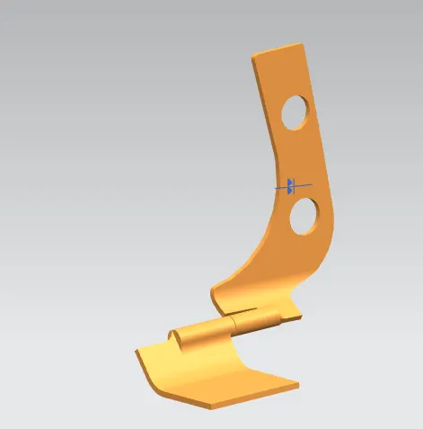
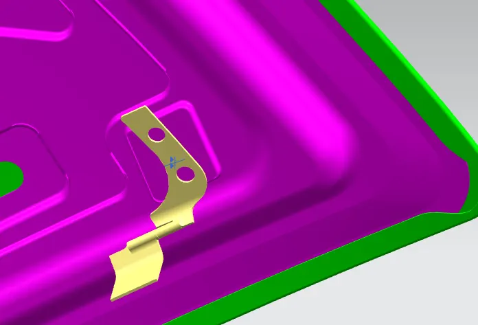
Striker Assembly -
Latch&striker is used for locking the hood with the car. It is usually placed on the space provided on the inner panel.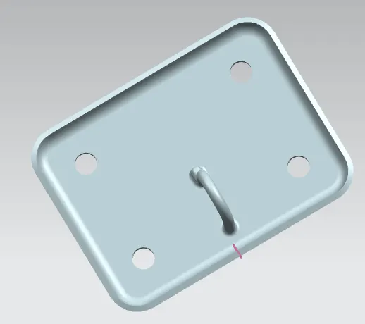
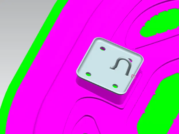
The process involved in designing hood for a car-
● Blanking
● Hemming
● Punch cutting or piercing
● Deep drawing
● Embossing
Hemming-
• Hemming is a sheet metal forming process in which sheets are joined by bending usually to 180 degrees. Automotive body panels & parts such as deck lids, trunk lids, doors, hoods & tailgates are formed by hemming processes.
• Conventional die hemming is suitable for mass production. In die hemming, the flange is folded over the entire length with a hemming tool. Normally the actual hemming is a result of a forming operation in which the flange is formed with a hemming tool after the drawing & trimming operations have been completed.
• Roll hemming is carried out incrementally with a hemming roller. An industrial robot guides the hemming roller & forms the flange. Roll hemming operation can also be divided into several pre-hemming & final hemming process steps. as shown in the below image
While doing the hemming process a relief angle is formed as a product of hemming when attaining at the corner of the sheet. So some relief is provided by trimming the sheet as shown below
Deep Drawing-
• Deep drawing is a manufacturing process that is used extensively in the forming of sheet metal into cup or box-like structures. Pots & pans for cooking, containers, sinks, and automobile parts, such as panel & gas tanks, are among a few of the items manufactured by sheet metal deep drawing.
• A deep drawing of sheet metal is performed with a punch and die. The punch is the desired shape of the base of the part, once drawn. The die cavity matches the punch and is a little wider to allow for its passage, as well as clearance. For many calculations, the sheet metal thickness is assumed to remain constant. There are changes in thickness in certain areas, due to the force involved.
here example is shown for the sitting arrangement of striker-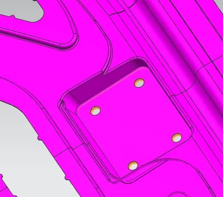
Embossing -
• The sheet metal embossing operation is commonly accomplished with a combination of heat & pressure on the sheet metal, depending on what type of embossing is required.
• A sheet metal is drawn through the male-female roller dies, producing a pattern or design on the sheet metal. Depending on the roller dies used, different patterns can be produced on the sheet metal.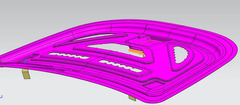
Now making of latch trajectory-
Latch trajectory -
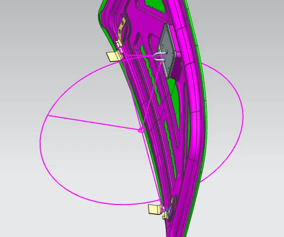
While opening or closing the hood, the latch must be perfectly aligned with the fixing or striker point. For that, the latch's trajectory must be perpendicular to the hinge axis.
so the hinge axis is made from hinge assembly and a datum plane is created at the centre of the hinge axis.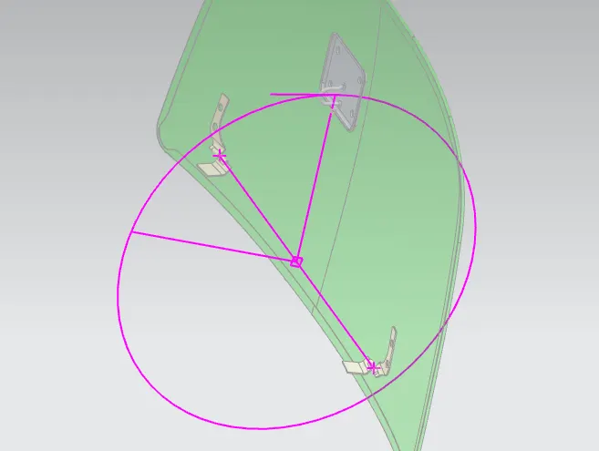
Final output-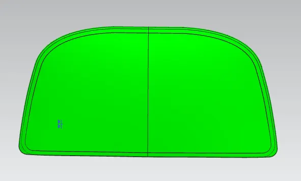
=============================================================
Thank you