Week 8 - Challenge 1 - Base Bracket Design
Submitted by: Syed Rizwan Ali
Course: Automotive plastic design Using Catia V5
Challenge: Week 8 - Challenge 1 - Base Bracket Design
1. A detailed report should be done explaining the draft analysis and the tooling axis creation.
Ans- Select the draft analysis then select the quick analysis mode then select the compass to the tooling axis, after that click anywhere on the Class A surface. A window popup and we can observe there 3 different color variations which means that we have given a draft angle of 3 degree
So, the green color represents the draft is more than three degrees
The blue color represents the draft is between 0 and 3 degrees
The red color represents whether the draft is negative or less than three.
Screenshots for the explanation of draft analysis-
Step 1 Class A Surface-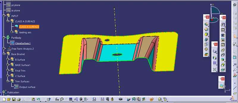
Step 2 Draft analysis -
Drag the compass to the tooling axis-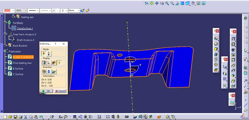
the color blue means the compass is upside down and by choosing flip we can turn into green, blue stand for draft angle below 0 degree
Step 3-
Click anywhere on the surface if it becomes complete green which means your draft analysis is correct-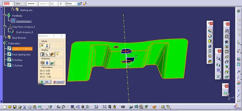
Tooling axis creation-
Now creating the tooling axis by using bisecting line and a dummy axis-
1. open the file which contains the Class A surface, after creating a geometrical set "Tooling Axis" then select the most appropriate position, and in this select a hole.
2. Then create a point in the center of the hole selected then draw a dummy line on the z-axis.
3. After that create a plane on the point created with reference to XY plane direction.
4. Then select the intersect tool that gives the intersection on the Class A surface.
5. Now create 2 lines using the point and direction method as shown below screenshot.
6. the Last step create a bisecting line using the above 2 lines and named it as Tooling axis after that hide the dummy tooling axis-
Have a look at the Screenshots
Dummy tooling and intersection-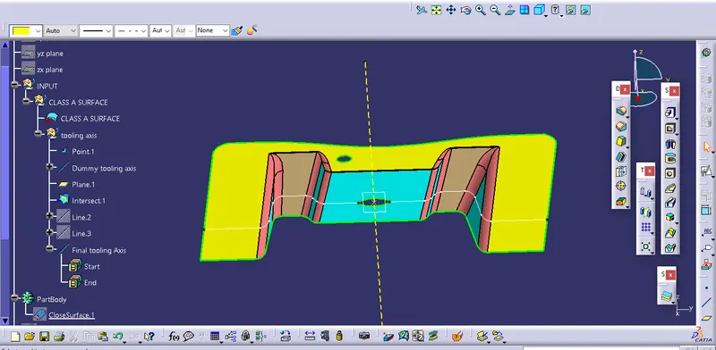
Creating 2 lines-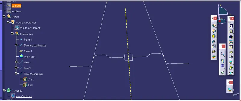
Creating Tooling axis using bisecting line-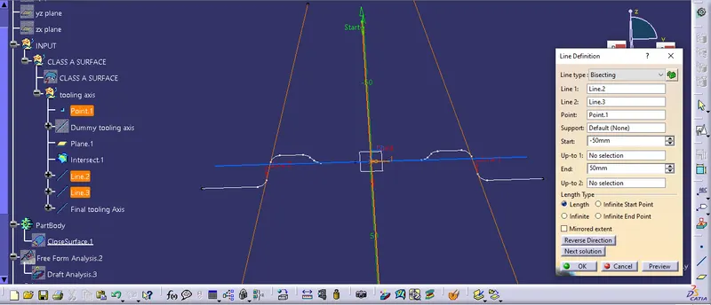
Above is the required detailed report on the draft analysis and Tooling axis.
Now we go further to create the final output surface using Class A, B, and C surfaces-
Creating B surface-
RIB1 and RIB 2-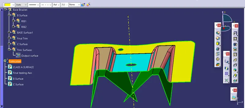
Bae extract-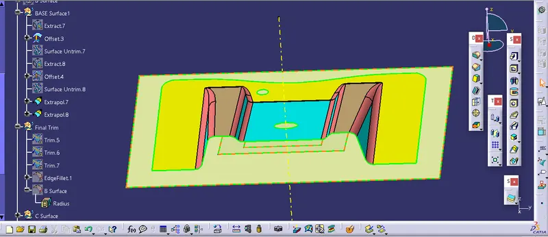
B Surface in Pink Color
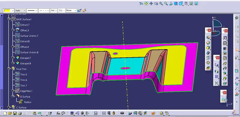
Now Creating C surface using Sweep, Boundary, and join commands-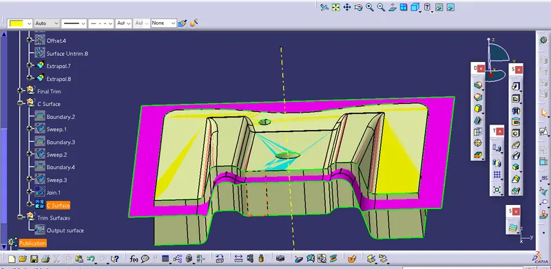
Final Output Surface- After trimming the B Surface from C surface the final plastic surface will form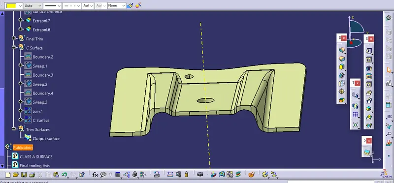
Go to part design and make the plastic surface solid to get the desired
base bracket surface component-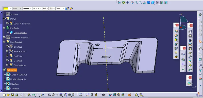
================================================================
Thank you