Week 9 - Project 1 - Door Trim Lower with Engineering Features
Submitted by: Syed Rizwan Ali
Course: Automotive Plastic design using Catia V5
Challenge: Week 9 - Project 1 - Door Trim Lower with Engineering Features
A detailed report should be done explaining the draft analysis and the tooling axis creation
Draft analysis on Class A surface-
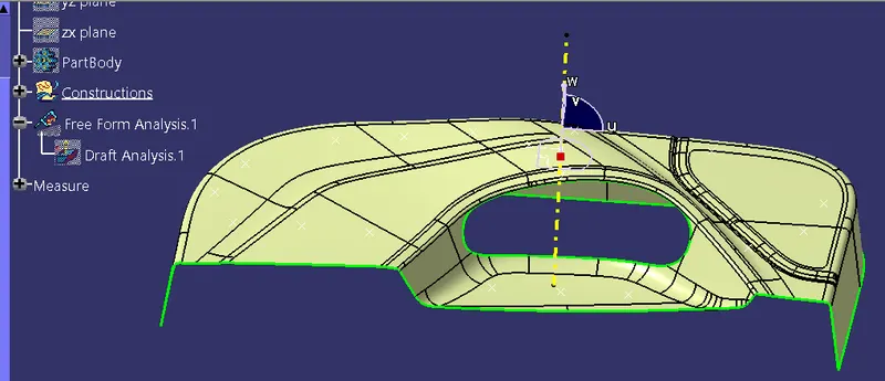
Step 1- Open draft analysis and move the compass to coincide with the Tooling axis as below
Step 2- Lock the compass and check the radius using the running analysis option-
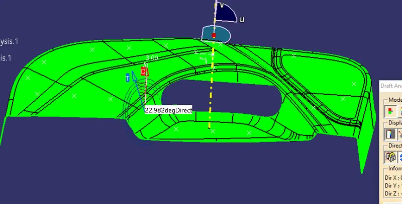
Step 3- Set the color code for the draft angle i.e green for above 1-3 degrees, Blue for 0 degrees, and red for angle value lesser than 0.
Step 4- Click on the surface using light effect, if the color goes green throughout means your draft analysis is good and ready for manufacture-
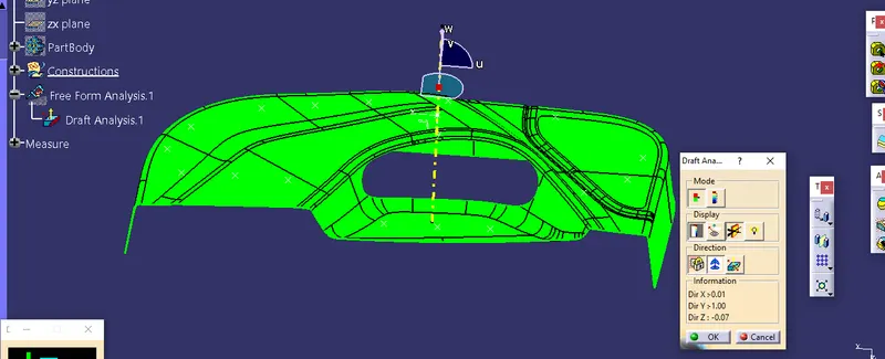
Using Class A surface creating B and C surfaces, and publishing same can be observed from tree structure of the below screenshot-
First tooling axis-
2-An explanation should be given on the way of creating the tooling axis, particularly the Bisecting method.
ANS- Tooling Axis-
Now creating the tooling axis by using bisecting line and a dummy axis-
1. open the file which contains the Class A surface, after creating a geometrical set "Tooling Axis" then select the most appropriate position, and in this select a base of the tab/pocket.
2. Then create a point at the surface extracted then draw a dummy line on the z-axis.
3. After that create a plane on the point created with reference to ZY plane direction.
4. Then select the intersect tool that gives the intersection on the Class A surface.
5. Now create 2 lines using the point and direction method as shown below screenshot.
6. the Last step creates a bisecting line using the above 2 lines name it Dummy Tooling Axis (In blue Color).
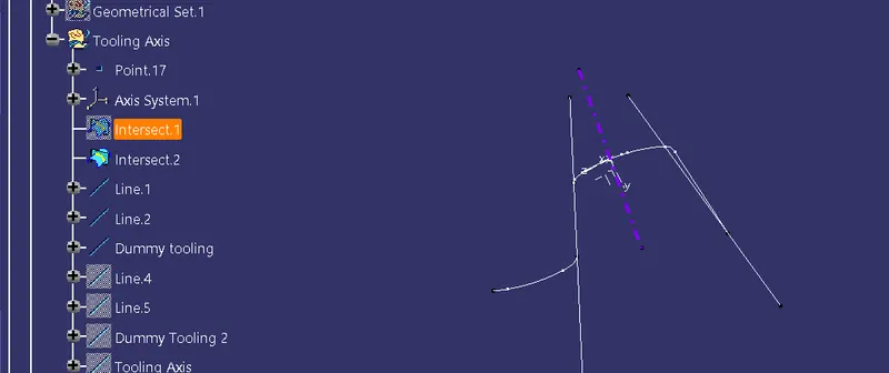
7. Now take an intersection of XY plane
8. make 2 lines using the point-point method
9. Create a Bisecting line using the 2 lines and name it Dummy tooling axis 2 (Sky blue color).
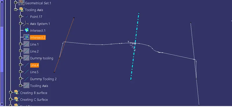
10. Final Step now take both dummy tooling axes and bisect them to get the final tooling axis (Yellow color)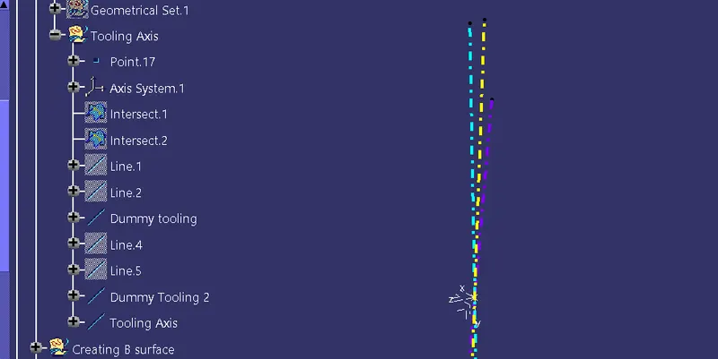
Now creating B surface, C surface, and B side Features using Class A surface.
B surface-
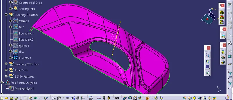
C Surface-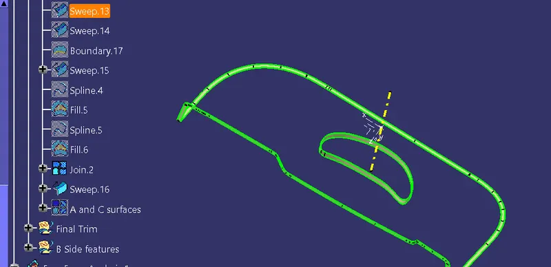
Combine C and A surfaces-
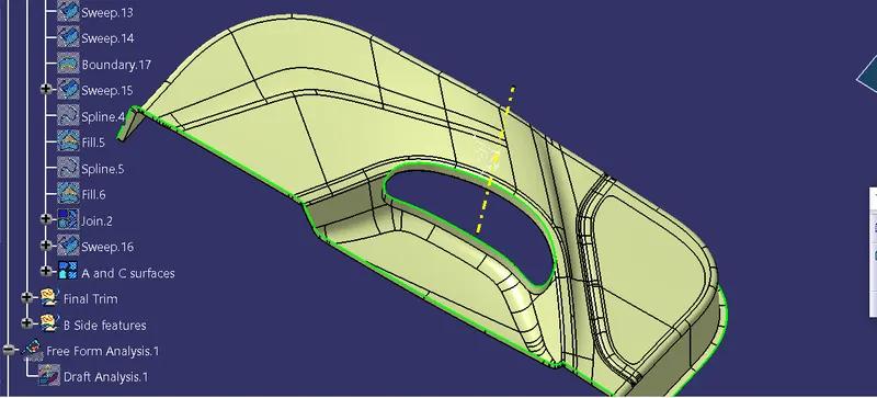
TRIM B surface and Combine of A and C to get the final output-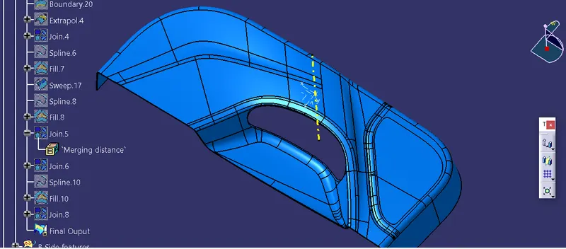
Making of B-side Features-
1. Fourway Locators and Heat stake-
To make the Heat stake point are and In blue color, there are 3 four-way locators-
Requirement for the features because these work on the principle of 3-2-1. i.e the Degree of freedom any object has are 12, so to arrest the maximum number of degrees and left only one, for fitting of counterpart-
Fourway locators sketch-
3 Fourway locators in blue color-
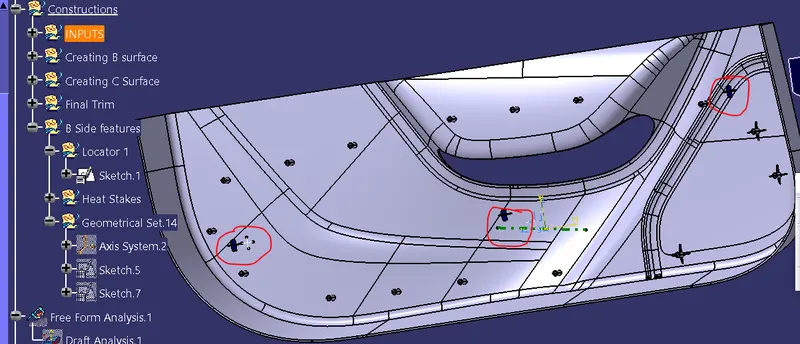
Now Heat stakes-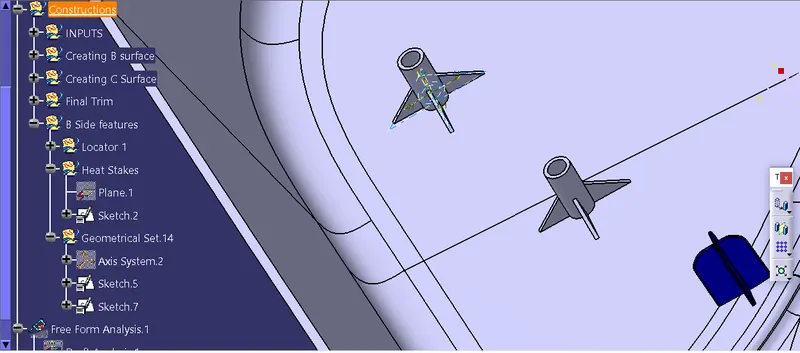
Now applying Draft analysis on final Solid product-
Steps will be the same as for class A surface-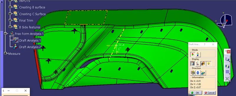
========================================================================
Thank you