Fender Design
Submitted by: Syed Rizwan Ali
Course: Automotive sheet metal design using Seimen's NX cad
Challenge: Fender Design
The Project is to create a front fender by using the given skin and creating the mountings like drip, sill, baffle, A-Pillar, and Bumper. Following the master, section create the design of the drip-
Fender:
A fender is a part of an automobile and other vehicles' body that frames a wheel well (the fender underside). Its primary purpose is to prevent sand, mud, rocks, liquids, and other road sprays from being thrown into the air by the rotating tire.
The main purpose of fenders on cars is to shield the wheels and protect the passengers, pedestrians, and other vehicles from stones, mud, liquid, and other debris that can fly in the air because these materials can be ejected from the surface of the tire at high velocity as the tire imparts kinetic energy to the attached objects. For a vehicle moving forward, the top of the tire is rotating upward and forward and can throw objects into the air at other vehicles or pedestrians in front of the vehicle.
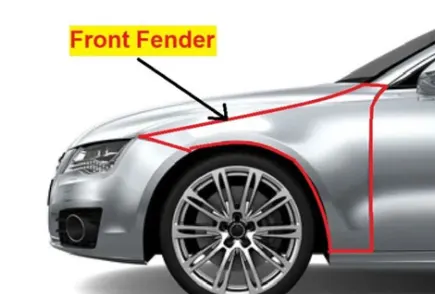
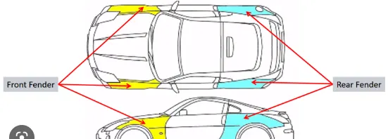
Types of Fender images-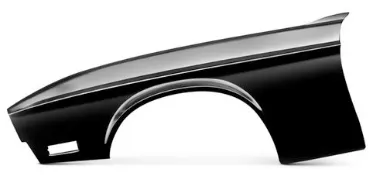
Fender mounts:
There are 5 different mounting positions in the design which are listed below-
1. Drip
2. Sill
3. Baffle(splash)
4. A-Pillar
5. Bumper
Fender Design and its different mounts-
Fender is drawn out from the given skin data. The complete fender design is shown below with all the mountings-
Skin Data/working surface
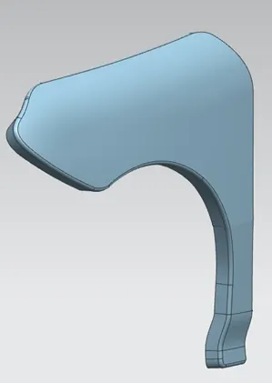
Complete fender=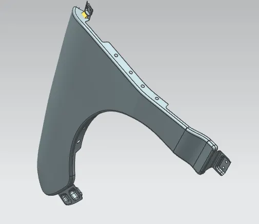
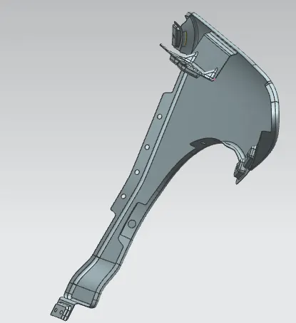
Fender Design procedure-
1. First offset the curve using a curve in the face command
2. Trim the flange as required by creating a curve on the face.
3. Create the desired flanges for all the mountings of the fender.
Now creating the flanges and mounting position on the fender-
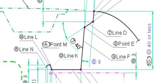
1. Drip- Used to assemble it with the engine compartment of a vehicle. The design of drip is made by following the given master section
- Trim the initial flange to 5mm as shown in the above image using offset curve and curve on the face.
- After trim, the drip area is created by using 2 datum planes, intersection.
- from front, the distance is 200 mm and from the back the distance is 150mm as shown in the master section.
- Create a flange of 5mm and 40degree from the horizontal axis.
- now keep in mind the total length of drip should 40mm or less.
- Create another flange of 35mm at 5 degree.
- Using Pythagoras' theorum and cosin, tan value
- Create 3rd flange at 0 degrees of 25mm
- Now create 2 more flanges at 45 degrees and 15 degrees
- Give the face blend of 5mm, 3mm, 3mm,3mm respectively
- Create embosses and 2 darts, trim holes for screwing
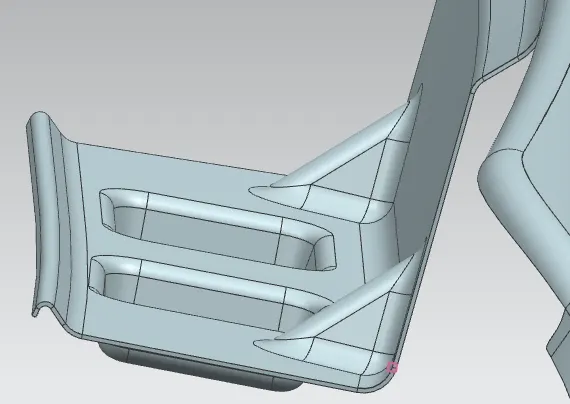
2. Sill- Bottom mounting is used to assemble it with the sill (sill is the lowermost part associated at the sides of vehicle BIW).
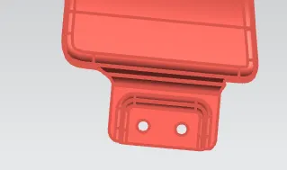
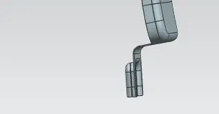
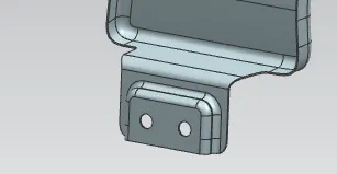
- The flange is trimmed off with the help of curves which are created before using the “curve on surface” command.
- Then law extension command is applied to create the required extension which is normal to the fender flange surface and its sharp corners were trimmed with help of a curve on face and trim sheet.
- A new plane is created with respect to the extension created before. On this plane, 2D sketch is created and projected to the sill mount extension.
- With help of these projected curves, embosses and fastener clearance holes were created.
3. Baffle/Splash: Under the fender and above the wheel these splashes are attached.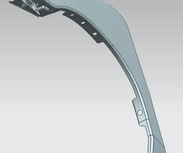
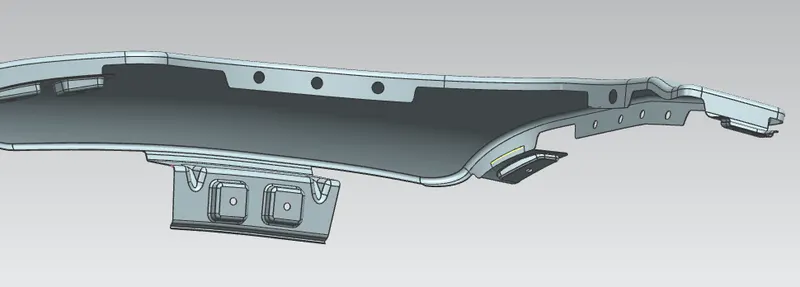
- The flanges were created by using an offset curve and trimmed
- Creating the clearance (hole) for mounting individual datum planes is created.
- 2D skecth of the circle is made and projected on the face which gets trimmed.
4. A-Pillar: Fender and A-pillar is get attached using this mounting.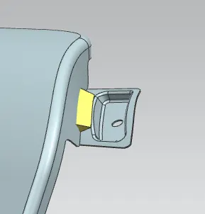
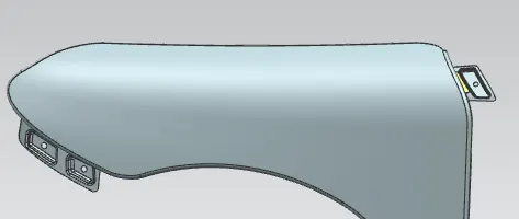
- Flanges is created the same as created for the other mounting
- This position is a bit different from others so the datum place is created using tanger and point through option
- the Emboss is created by using a datum plane instead of a face
- To support the hanging flange bead is created.
5. Bumper mount: It is a mount in the front fender, which is used to assemble it with the bumper part.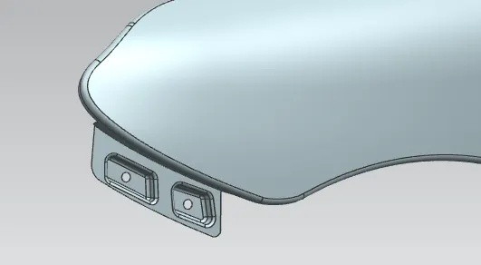
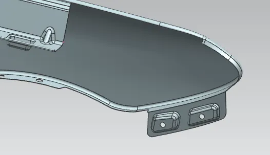
- The unwanted region in the flange is trimmed off with the help of curves which are created before using the “curve on surface” command.
- Then law extension command is applied to create the required extension which is normal to the fender flange surface and its sharp corners were trimmed with help of curves on faces.
- A new plane is created with respect to the extension created before. On this plane 2D sketch is created and projected to the bumper mount extension.
- With help of these projected curves, embosses and fastener clearance holes were created.
- Finally, the blends were created at the sharp edges and corners.
Manufacturing process: Sheet metal is made by running hot slabs of metal through a series of rough rolling stands that makes them thinner and longer. To make them even thinner, these sheets go through finishing rolling stands and are then cooled and rolled into coils.
Types of processes
Bending: In bending, force is applied to a sheet metal workpiece to produce a curvature of the surface. Bending is generally used to produce simple curved surfaces rather than complex ones. A mechanically operated press drives a punch against sheet metal, forcing it into a simple die with enough pressure to produce a permanent change in the metal's shape. The amount of pressure is important. If not enough pressure is applied, the metal can simply spring back into its original shape. If too much is applied, it can break.
Drawing: In the drawing, the sheet metal is forced against a die that has been cut into the three-dimensional, often curved shape that the sheet metal is to take on. In effect, the die is used as a mold for the metal. This technique can produce relatively complex shapes. Once again, pressure is applied to the workpiece using a hydraulically or mechanically operated punch. It can crack from too much pressure or wrinkle from its interaction with the die. Lubricant can be used to make the metal slide more smoothly against the die, avoiding the possibility of wrinkling. Alternatively, the wrinkled edges can be trimmed from the metal in a separate operation. This method is commonly used to make auto body parts and fuel tanks.
Stamping: In stamping, a device called a stamping press is used with a series of dies to cut and form metal into various shapes. This is commonly used to make auto parts such as hubcaps and fenders.
Extrusion: Extrusion can be used to produce long metal objects, such as rods and tubes. The metal workpiece is forced into a die with a hole in the opposite end. The metal is extruded through the hole to form the shape. Extrusion can be used to manufacture important parts of a car's drive train or the anchors that hold seatbelts in place.
Forging: The forging process uses a hammer or press that is essentially a mechanized version of the hammers used by ancient blacksmiths. The metal is hammered against a surface that serves as an anvil. It can be hammered repeatedly so as to form complex shapes. This can be used as an alternative to the drawing process.
Design parameters:
There are certain standards are followed by the OEMs for designing automotive commodities, these standards are framed from the trial and error method which is carried out by the OEMs and automotive industries to meet safety requirements, reduce the production cost, and material wastage, and increase the efficiency of the components. As we saw before, a fender consists of 5 major mounts. These mounts are designed with respect to their standards and given parameters. Some common parameters for a fender design are, the blends should be a minimum of 2.5mm radius to avoid sharp edges, then there must be a clearance of about 3mm - 5mm between the blends and the fastener holes.
=============================================================