Week 8 - Challenge 6 - Core & Cavity Design
Submitted by: Syed Rizwan Ali
Course: Automotive plastic design using Catia V5
Challenge: Week 8 - Challenge 6 - Core & Cavity Design
1- A detailed report should be done explaining the draft analysis and the tooling axis creation.
Draft analysis on Class A surface of Switch Bezel below-
Step 1- Open draft analysis and move the compass to coincide with Tooling axis as below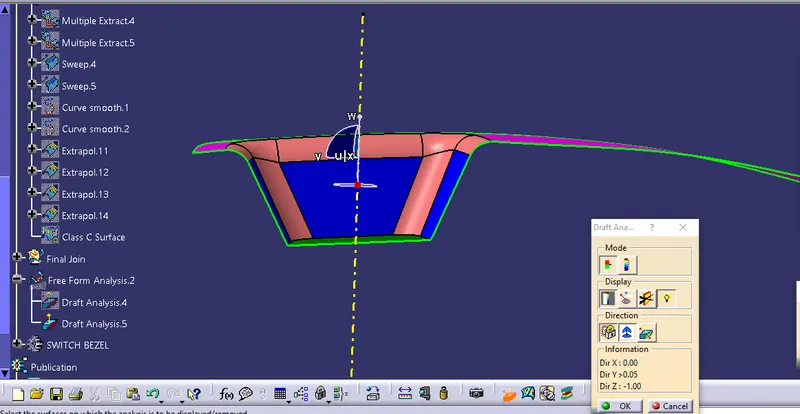
Step 2- Lock the compass and check the radius using the running analysis option-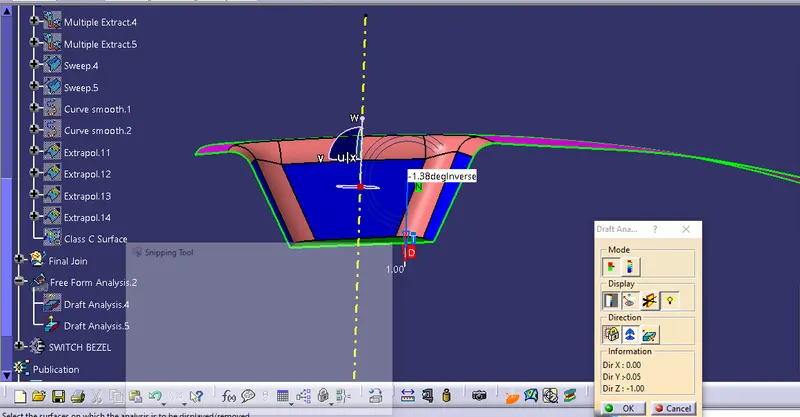
Step 3- Set the color code for the draft angle i.e green for above 3 degrees, Blue for 0-3 degrees, and red for angle value lesser than 0.
Step 4- Click on the surface using light effect, if the color goes green throughout means your draft analysis is good and ready for manufacture-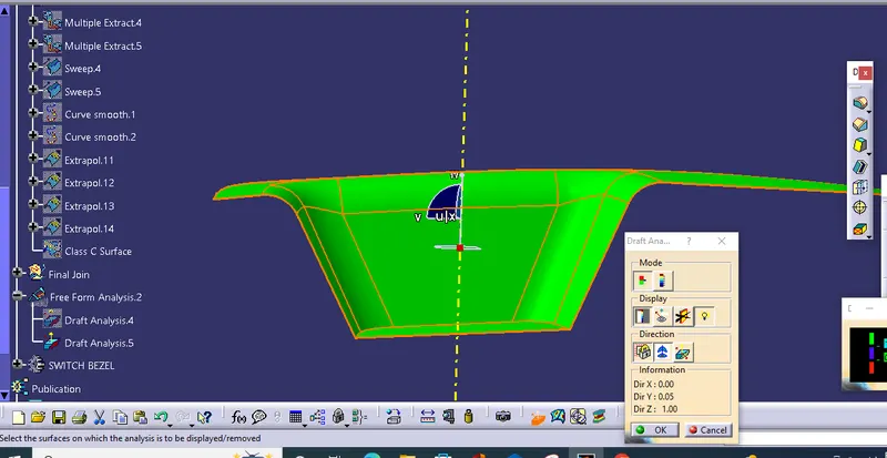
Now Creating Tooling Axis-
2-An explanation should be given on the way of creating the tooling axis, particularly the Bisecting method.
ANS- Tooling Axis-
Now creating the tooling axis by using bisecting line and a dummy axis-
1. open the file which contains the Class A surface, after creating a geometrical set "Tooling Axis" then select the most appropriate position, and in this select a base of the tab/pocket.
2. Then create a point at the surface extracted then draw a dummy line on the z-axis.
3. After that create a plane on the point created with reference to XY plane direction.
4. Then select the intersect tool that gives the intersection on the Class A surface.
5. Now create 2 lines using the point and direction method as shown below screenshot.
6. the Last step creates a bisecting line using the above 2 lines.
Have a look at the Screenshots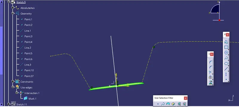
The above line is made for the Y direction and making the line for the X direction with the same procedure used above
But in this, we need to draw a line manually and keep its angle to 6 degrees-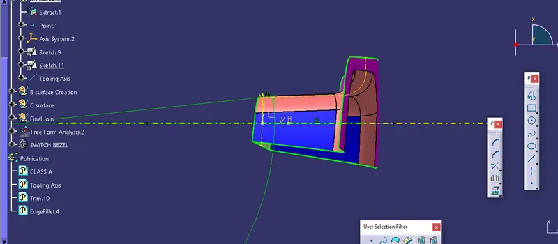
The final step for the Tooling axis -
Bisect the lines created in sketch 9 and sketch 11 using the bisecting line command-
Color it yellow and published it.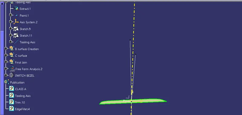
Designing for Mold by creating Core and Cavity for switch bezel-
1. Creating Parting Surface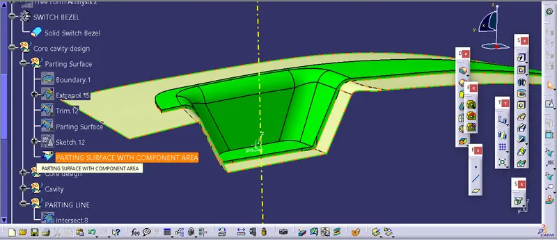
First, take the boundary of the Class A surface and extrapolate it to 15 mm now,
Trim it with a C surface and make a sketch of a Rectangular shape and Trim that with the last trim to get the parting surface.
Core- Extrude the same sketch in the tooling direction, trim it with a parting surface, and use the fill command-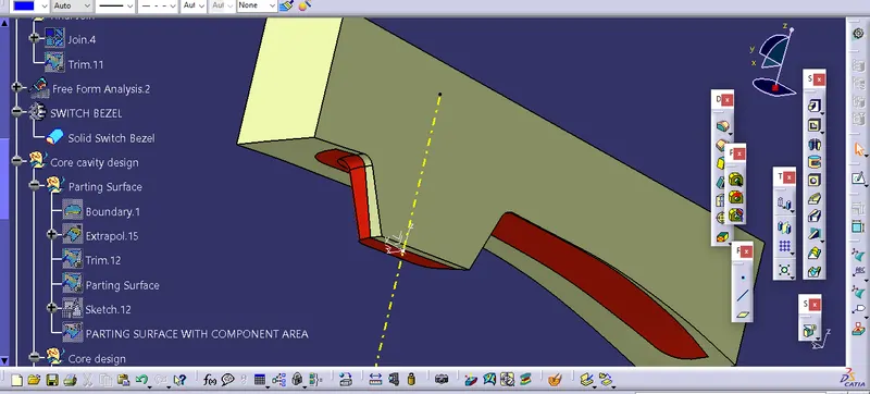
CAVITY-
Extrude the same sketch and trim it parting surface-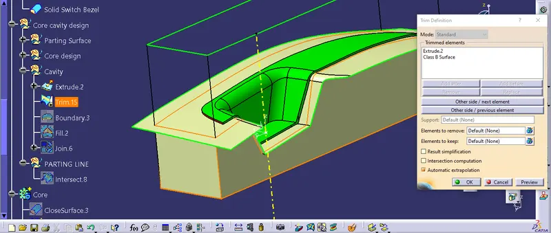
Fill the trim and join them to get the cavity mold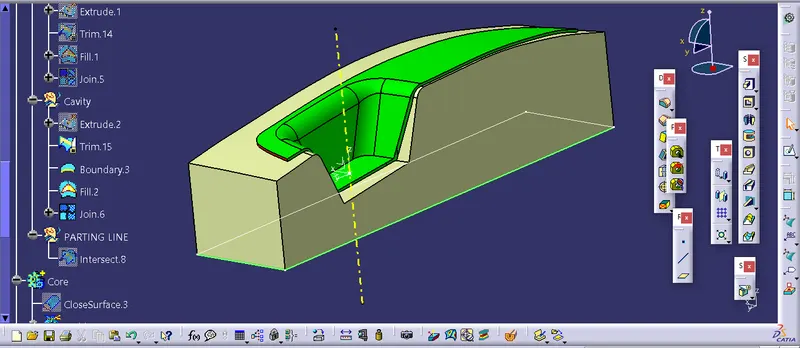
NOW Creating Parting line-
Parting line the join or slip project of Class A and B and C colored in Red line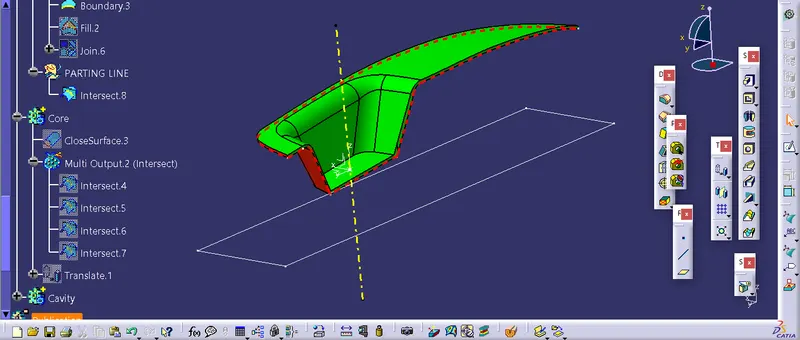
INside view can me observed via dynamic section of the core and cavity and we can also check them using parting lines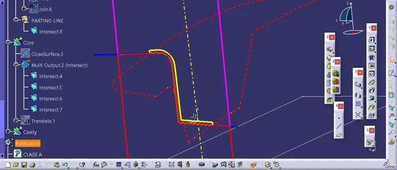
Dynamic section so that we can see inside the mold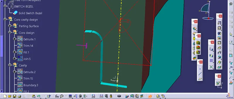
=========================================================
Thanks