Fender Design - Wheel Arch Challenge
Submitted by: Syed Rizwan Ali
Course: Automotive sheet metal design using Seimen's NX cad
Challenge: Fender Design - Wheel Arch Challenge
The project is to study the different Fender wheel Arch Regulations and to calculate the European standard regulation on the given fender and wheel.
Fender:
A fender is a part of an automobile and other vehicles' body that frames a wheel well (the fender underside). Its primary purpose is to prevent sand, mud, rocks, liquids, and other road sprays from being thrown into the air by the rotating tire.
The main purpose of fenders on cars is to shield the wheels and protect the passengers, pedestrians, and other vehicles from stones, mud, liquid, and other debris that can fly in the air because these materials can be ejected from the surface of the tire at high velocity as the tire imparts kinetic energy to the attached objects. For a vehicle moving forward, the top of the tire is rotating upward and forward and can throw objects into the air at other vehicles or pedestrians in front of the vehicle.
Types of Fender images-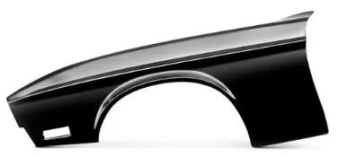
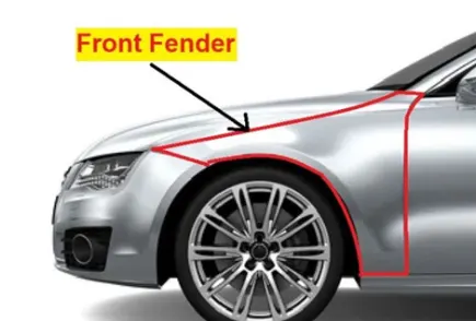
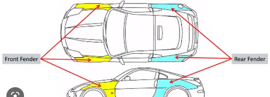
Types of fender
The type of fender is based upon the area covered i.e., full fender type and half fender type.
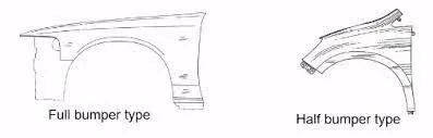
- Full fender type:
The full fender type is the traditional type of fender where more material consumption is observed. This type is used in the old designs of automobiles where it increases the overall weight and thus reduces performance. The maintenance is also relatively more due to more surface.
- Half fender type:
Half fender type is modern design where less material consumption is observed, so productivity increases by reducing size of blank and thus providing more performance. The maintenance also relatively low compared to full bumper type.
As we know that every continent has varying physical conditions and many countries has their own standard for fender because of the physical condition of terrain surfaces or roads. So below listed are the Fender Wheel Arch Regulations :
1. Japan Regulations
2. European Regulations
3. US Regulations
Japan Regulations :
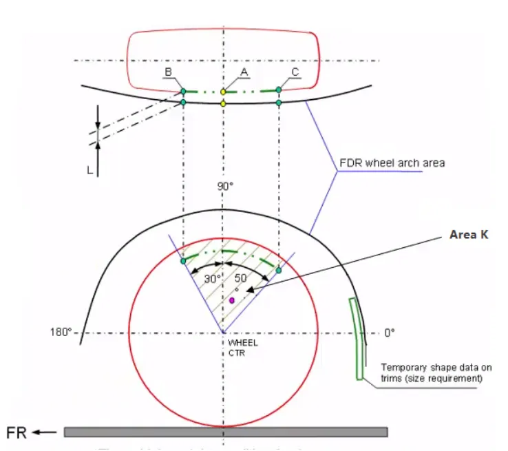
- The clearance ‘L’ for tire, hub, cap, and fender is to be measured within area K and create clearance check chart to validate
- The value of L should be greater than 5mm at all positions
- Wheel guard requirement: The value of ‘a’ should be more than 5mm at line 30° forward and 50° rearwards from the central vertical axis of the wheel
=============================================================
European Regulations:
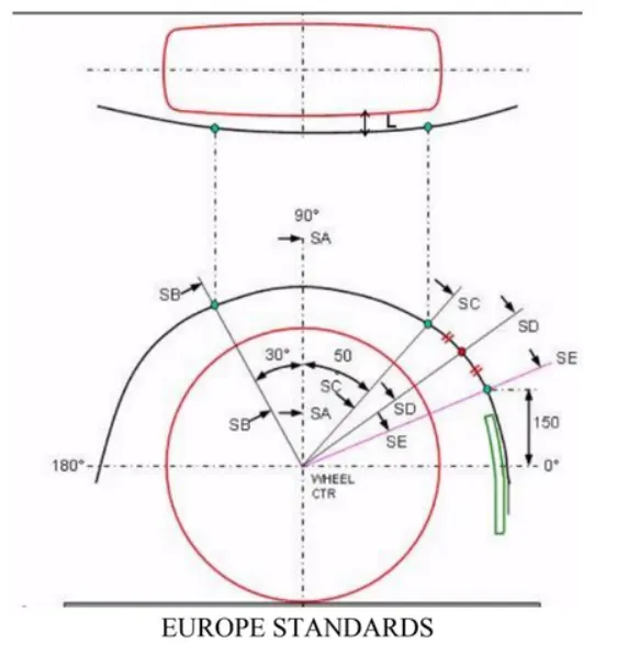
1. The Clearance ‘L’ should be measured at sections SA-SA, SB-SB, SC-SC, SD-SD and SE-SE and create a clearance check chart to validate
2. At all the five sections the value of L should be greater than 10mm to satisfy the European Regulations
3. Wheel guard requirement: The value of ‘a’ should be more than 5mm at line 30° forward and 50° rearwards from the central vertical axis of the wheel
=========================================================
US Regulations:
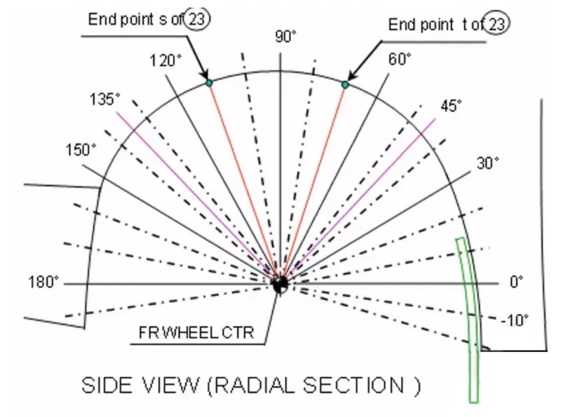
1. Clearance ‘L’ is to be checked at all positions from -100° to 100° and create clearance check chart to validate
2. The value of L should be greater than 5mm to satisfy the regulations
3. Wheel guard requirement: The value of ‘a’ should be more than 5mm at line 30° forward and 50° rearwards from the central vertical axis of the wheel
=============================================================
calculate the European standard regulation on the given fender and wheel.
For the calculation of clearance between the Wheel Arch and the Wheel, we have to create a sketch on the outermost face of the wheel. Below are the steps to follow-
1. A Datum Plane is created at the outermost face of the wheel
2. The sketch is created on the new Datum Plane
3. A Horizontal line is drawn across the center of the wheel
4. A perpendicular line SA is dropped at the center of the wheel
5. Two lines SB and SC are created at 30° forward of SA and 50° rearward of SA respectively
6. A point is created 150mm vertically above the center line
7. A-line SE is drawn from the wheel center and passes from the point created
8. Another line SD is drawn from the center of the wheel and in the middle of lines SC and SE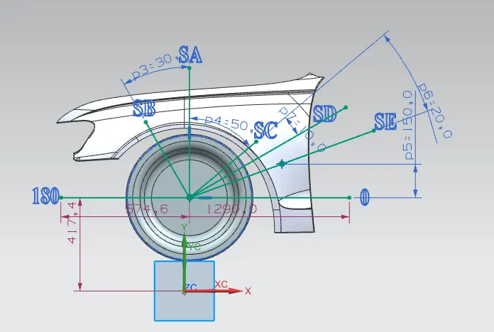
Obtaining the clearance L at the designated 5 points
The clearance distance 'L' is calculated at points SA-SA, SB-SB, SC-SC, SD-SD and SE-SE, which should be greater than or equal to 10mm.
1. Measuring distance clearance 'L' at SA-SA
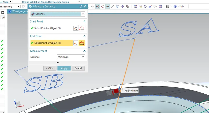
L = 9.9490 mm
2. Measuring distance clearance 'L' at SB-SB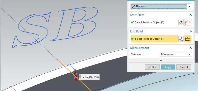
L = 10.00 mm
3. Measuring distance clearance 'L' at SC-SC
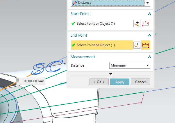
L = 0.00
4. Measuring distance Clearance 'L' at SD-SD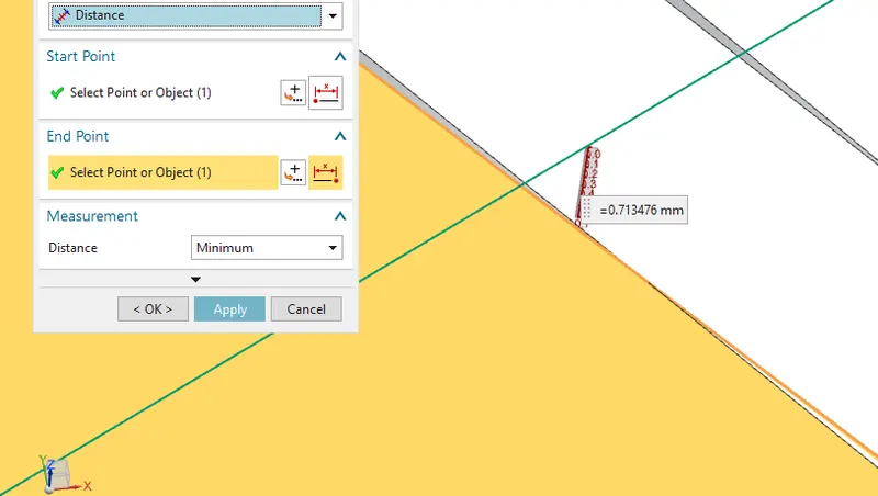
L= 0.713476
5. Measuring distance clearance 'L' at SA-SA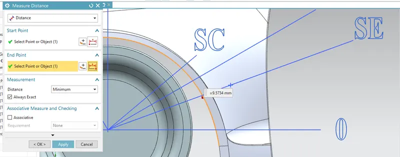
L=9.5734
Measuring the clearance value 'a' for Wheel Guard Requirement
1. Clearance 'a' at 30° line SB
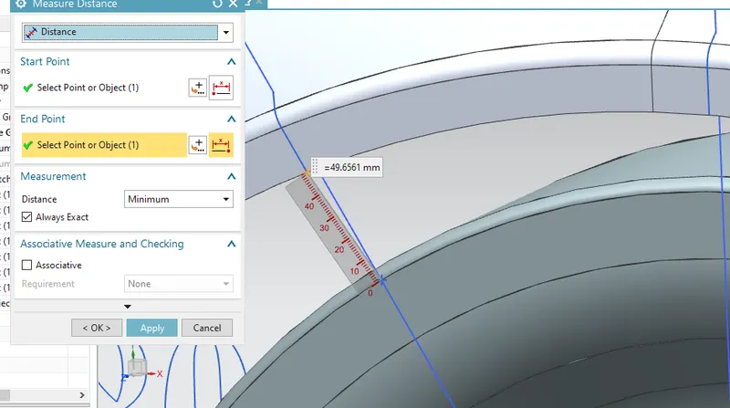
a= 49.6561 mm
2. Clearance 'a' at 50° line SC
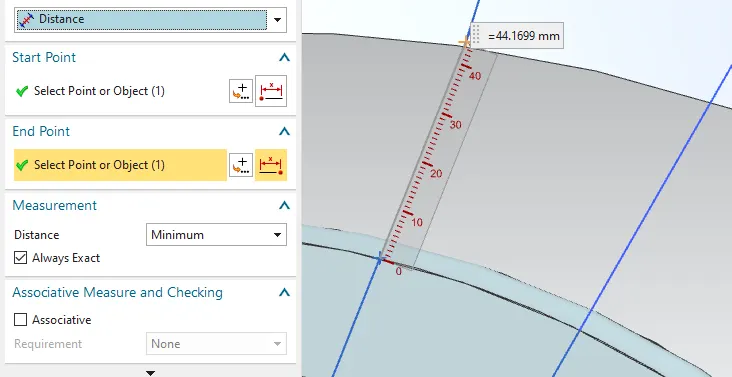
a = 44.1699
Result :
| Section | L(>10mm) | Result | a(>5mm) | Result |
| SA-SA | 9.9490 | Fail | ||
| SB-SB | 10.00 | Pass | at 30degree | Pass |
| SC-SC | 0.00 | Fail | at 50 degree | Pass |
| SD-SD | 0.713476 | Fail | ||
| SE-SE | 9.5734 | Fail |
From the above results, we can conclude that the Fender does not pass the European Regulations, as the minimum clearance L between the Fender Wheel Arch and Wheel for vehicle and pedestrian safety is 10mm and this design does not meet the requirement. So we'll ask the class engineer to amend the design to the suggested changes.
=========================================================4
Thank you