Study of Interfaces and Effect of Notch in Buckling on a Crush Tube
OBJECTIVE
Crush Tube Analysis
PROCEDURE
a) Initial Setup:
i) Select Radioss from the user interface menu.
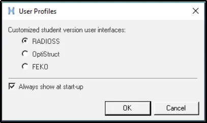
ii) First, we need to import the model into Hypermesh.
iii) To do so, click on Import -> Import Solver Deck -> Choose the starter file -> Import.
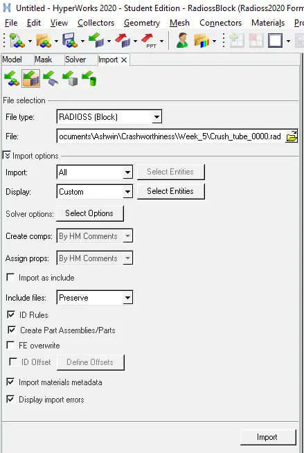
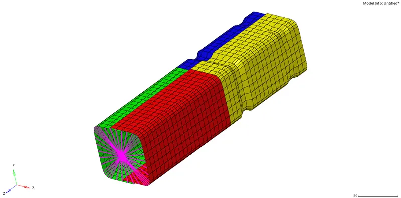
iv) After importing the following model is obtained:
b) Meshing:
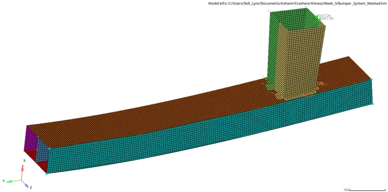
i) The model is meshed using automesh option and appropriate connections were given.
ii) The model is shown below:
c) Case 1:
i) Run the simulation of the model without making any changes.
ii) To do the analysis, click on Analysis -> Radioss -> Select the file location and name -> Check 'include connectors' box -> Options = '-nt 4' -> Radioss.

[Note: When '-nt 4' is given in the options bar, the simulation will utilize 4 cores of the CPU thereby decreasing simulation time]
iii) To view the simulation, switch the menu to HyperView.
iv) Choose the required '.h3d' file from the simulation folder.

v) To plot the graphs we have to switch to HyperGraph 2D.
vi) Select the required T01 file from the simulation folder.

vii) To monitor the von mises stress in the simulation, click on Contour -> Result type=Von Mises(s) -> Averaging Method= Simple -> Apply.

viii) The following output is obtained:
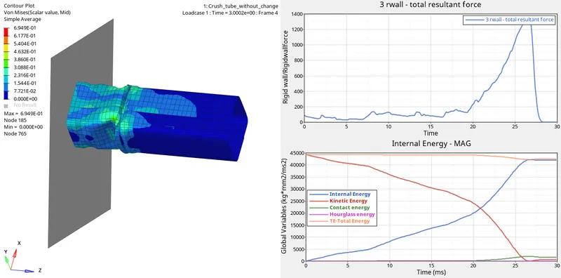
d) Case 2:
i) Change Inacti=6 and run the model.
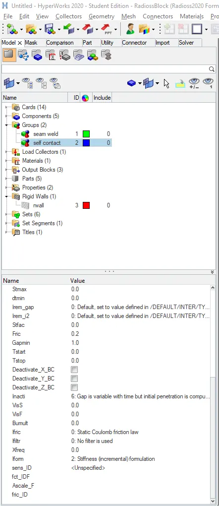
ii) Follow the aforementioned procedure to run the simulation and plot the graphs.
iii) The following output is obtained:
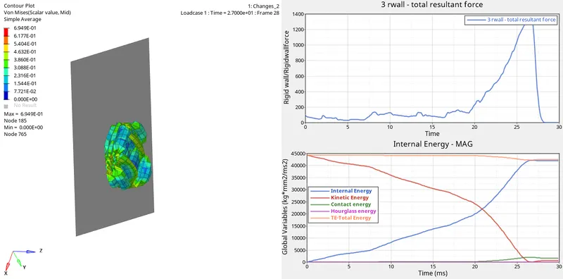
d) Case 3:
i) Create type 11 contact and run the model.
ii) To do so, click on Model -> Groups -> Create -> Card Image -> Type=11 -> Select the recommended properties.
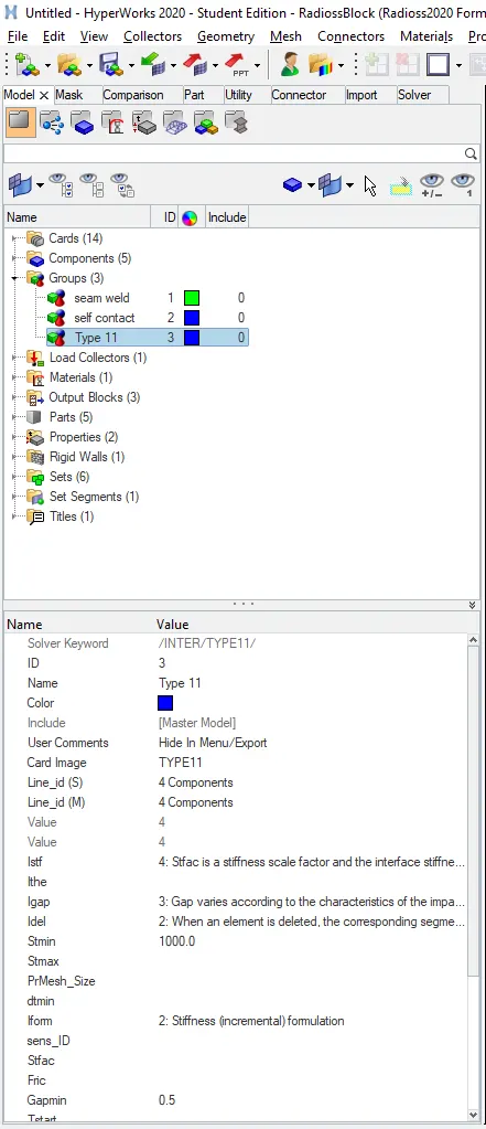
iii) Follow the aforementioned procedure to run the simulation and plot the graphs.
iv) The following output is obtained:
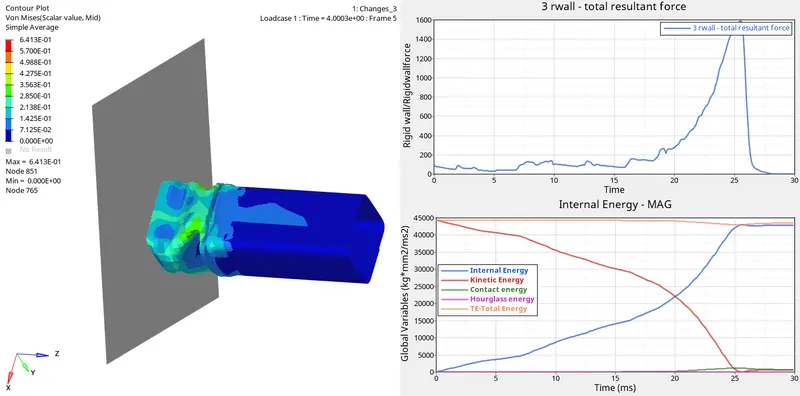
e) Case 4:
i) Remove both the notches and the boundary condition on the rigid body node.
ii) The notch can be removed by using the Align node tool.
iii) To do so, click on Geom -> Node edit -> Align node -> Select the reference nodes -> Select the nodes to be aligned.

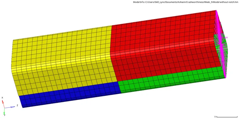
[Note: Shortcut for Node Edit tool is F7]
iv) Remove the boundary condition on the master node.
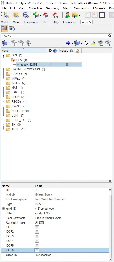
v) Follow the aforementioned procedure to run the simulation and plot the graphs.
vi) The following output is obtained:
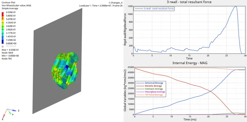
f) Case 5:
i) Create a new notch in the middle using the translate tool.
ii) To do so, click on Tools -> Translate -> Select the elements -> Select N1,N2 -> Magnitude=10.

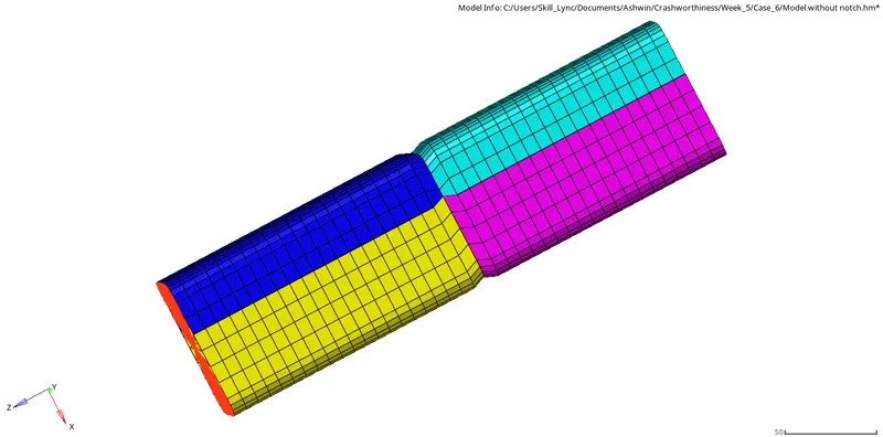
[Note: Shortcut for Translate tool is Shift + F4]
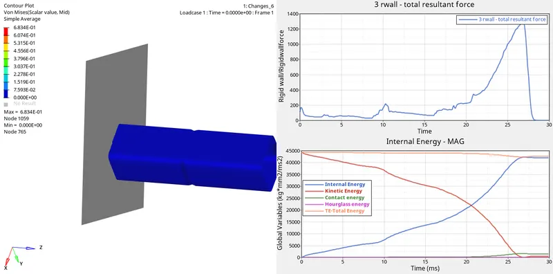
ii) Follow the aforementioned procedure to run the simulation and plot the graphs.
iii) The following output is obtained:
g) Case 6:
i) Create a notch on opposite faces only using the translate tool.
ii) To do so, click on Tools -> Translate -> Select the elements -> Select N1,N2 -> Magnitude=10.
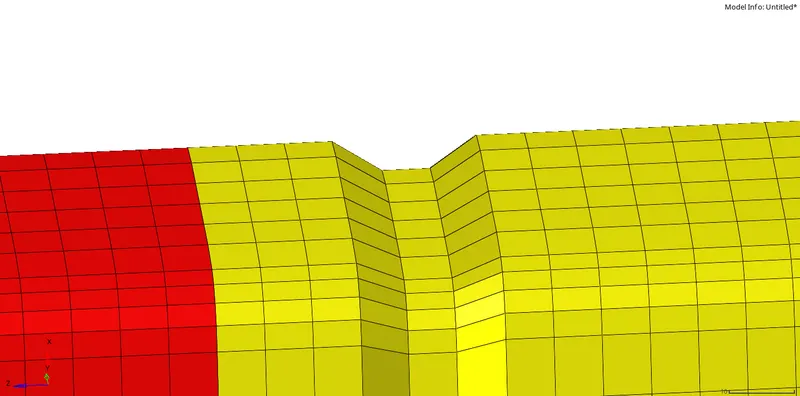
[Note: Shortcut for Translate tool is Shift + F4]
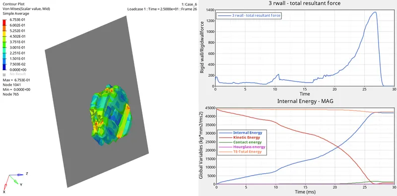
ii) Follow the aforementioned procedure to run the simulation and plot the graphs.
iii) The following output is obtained:
RESULTS
a) Case 1:
| Sl. No | Name | Image | Observations |
| 1. | Von Mises Stress | 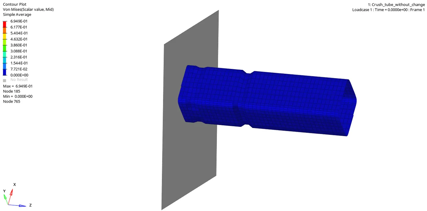 |
|
| 2. | Internal Energy | 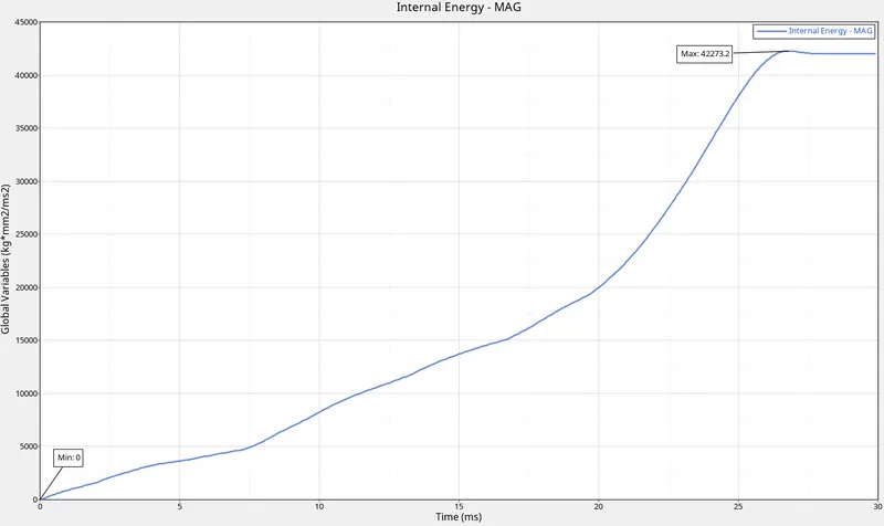 |
|
| 3. | Kinetic Energy | 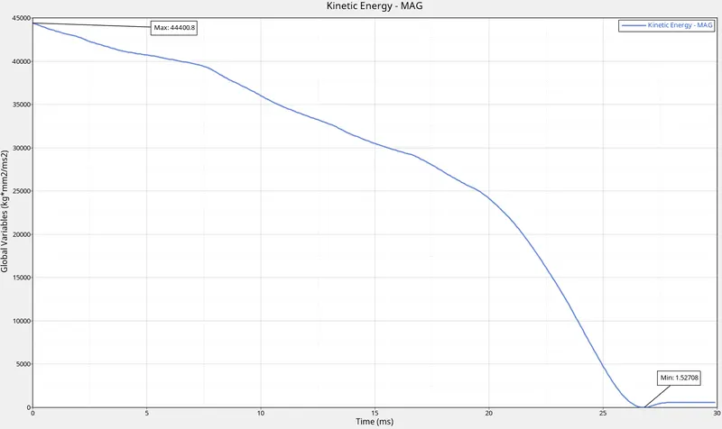 |
|
| 4. | Contact Energy | 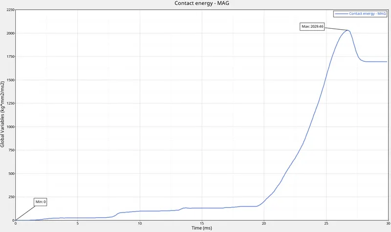 |
|
| 5. | Hourglass Energy | 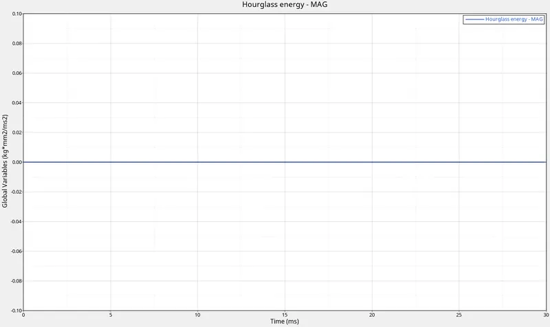 |
|
| 6. | Rigid Wall | 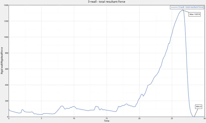 |
|
| 7. | Total Energy | 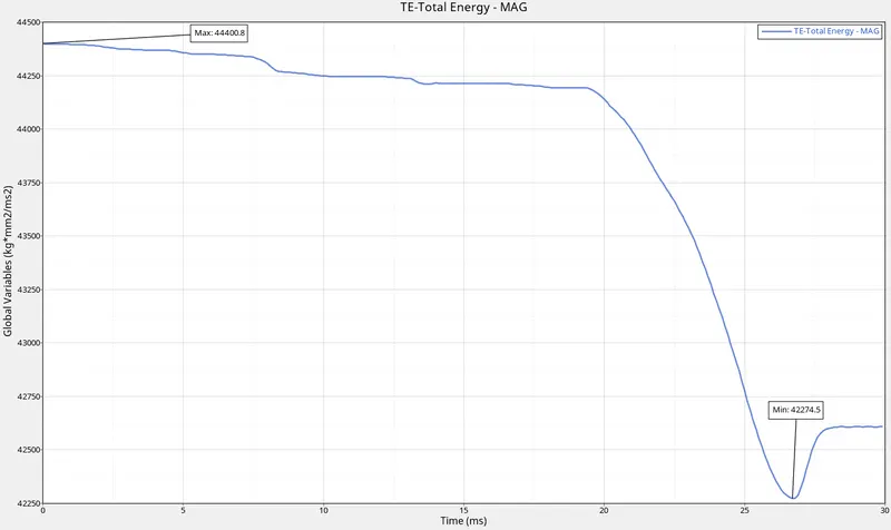 |
|
| 8. | All Graphs | 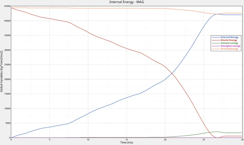 |
|
| 9. | Energy and Mass error | 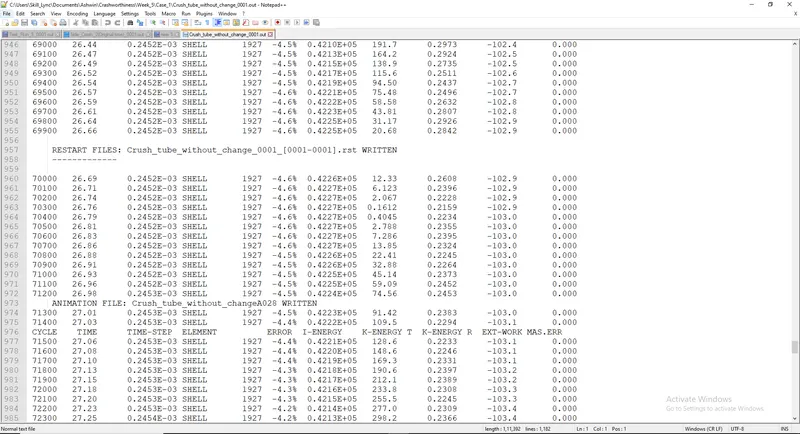 |
|
| 10. | Run Time | 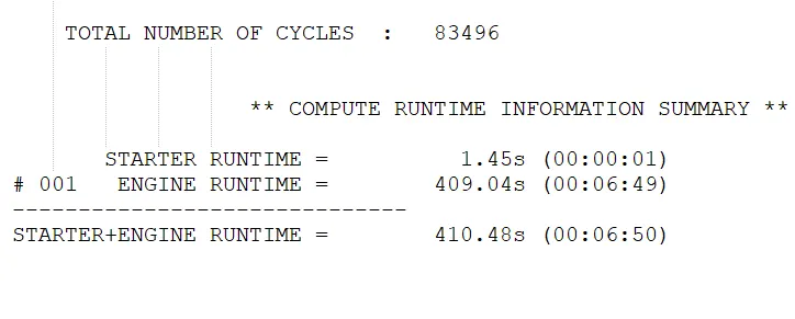 |
|
b) Case 2:
| Sl. No | Name | Image | Observations |
| 1. | Von Mises Stress | 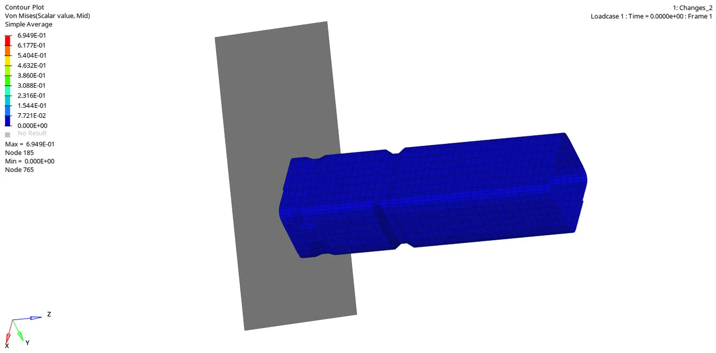 |
|
| 2. | Internal Energy | 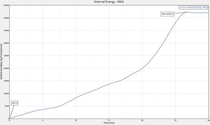 |
|
| 3. | Kinetic Energy | 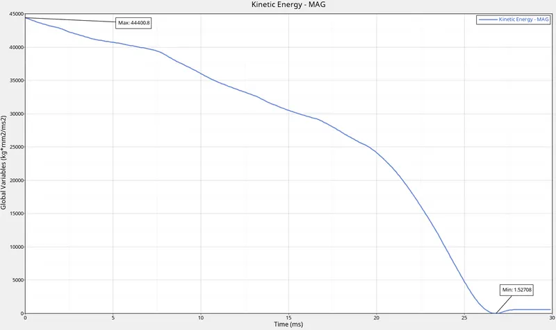 |
|
| 4. | Contact Energy | 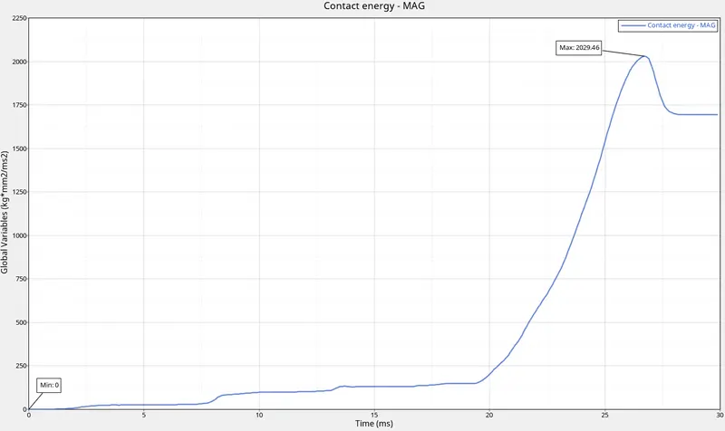 |
|
| 5. | Hourglass Energy | |
|
| 6. | Rigid Wall | 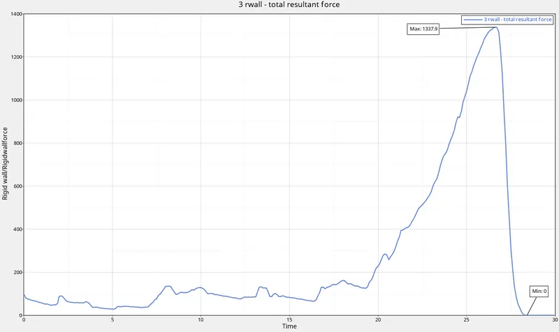 |
|
| 7. | Total Energy | 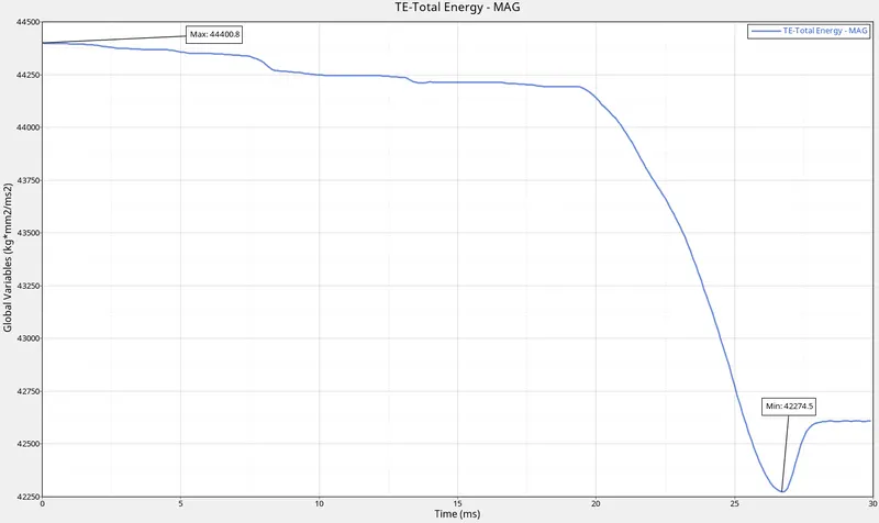 |
|
| 8. | All Graphs | 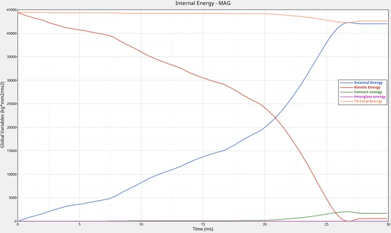 |
|
| 9. | Energy and Mass error | 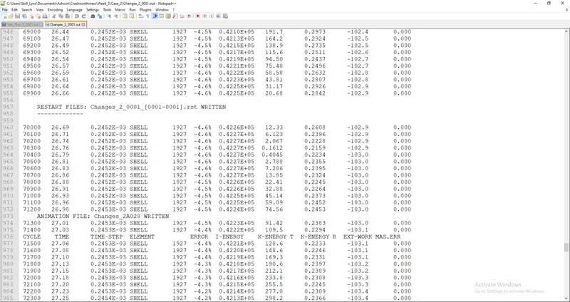 |
|
| 10. | Run Time | 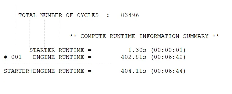 |
|
c) Case 3:
| Sl. No | Name | Image | Observations |
| 1. | Von Mises Stress | 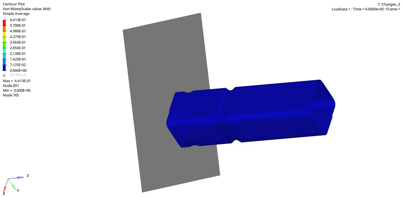 |
|
| 2. | Internal Energy | 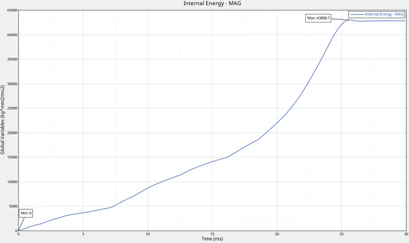 |
|
| 3. | Kinetic Energy | 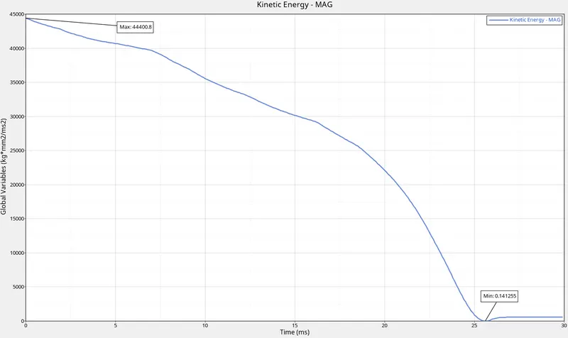 |
|
| 4. | Contact Energy | 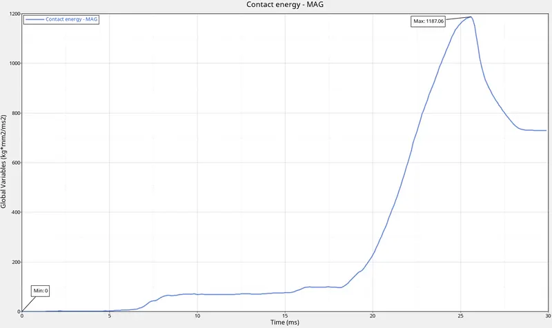 |
|
| 5. | Hourglass Energy | |
|
| 6. | Rigid Wall | 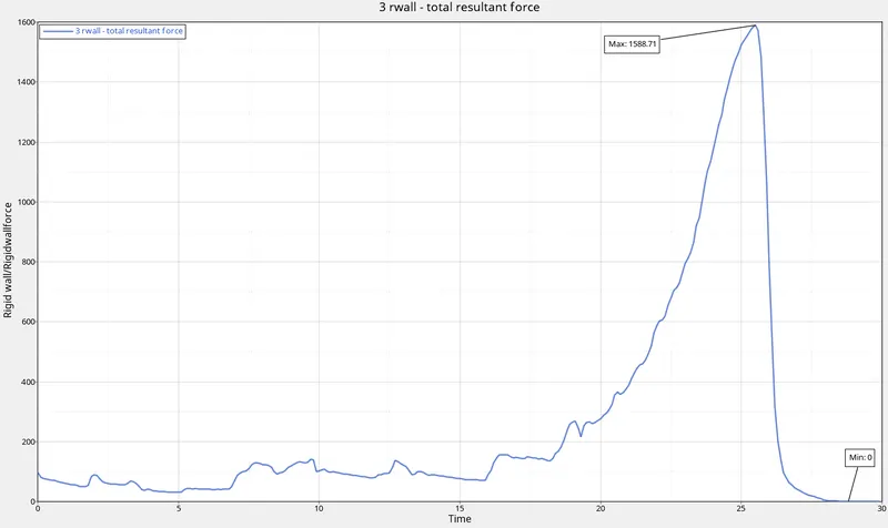 |
|
| 7. | Total Energy | 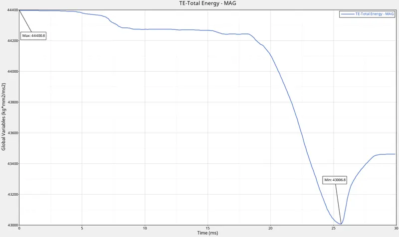 |
|
| 8. | All Graphs | 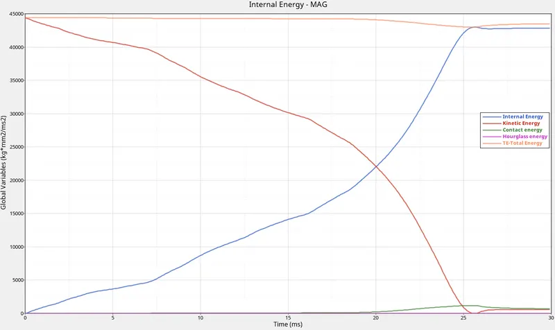 |
|
| 9. | Energy and Mass error | 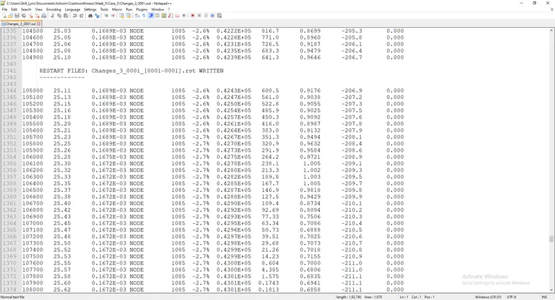 |
|
| 10. | Run Time | 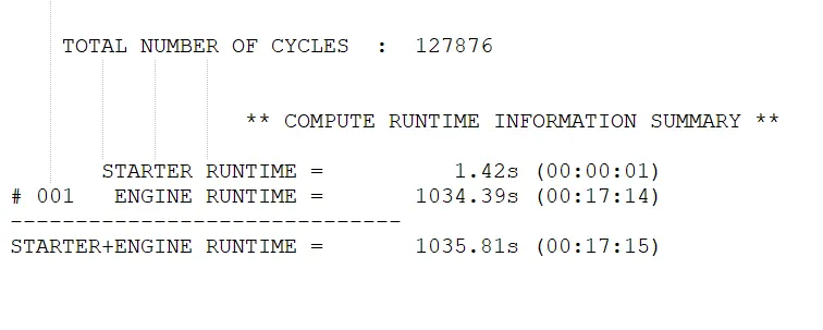 |
|
d) Case 4:
| Sl. No | Name | Image | Observations |
| 1. | Von Mises Stress | 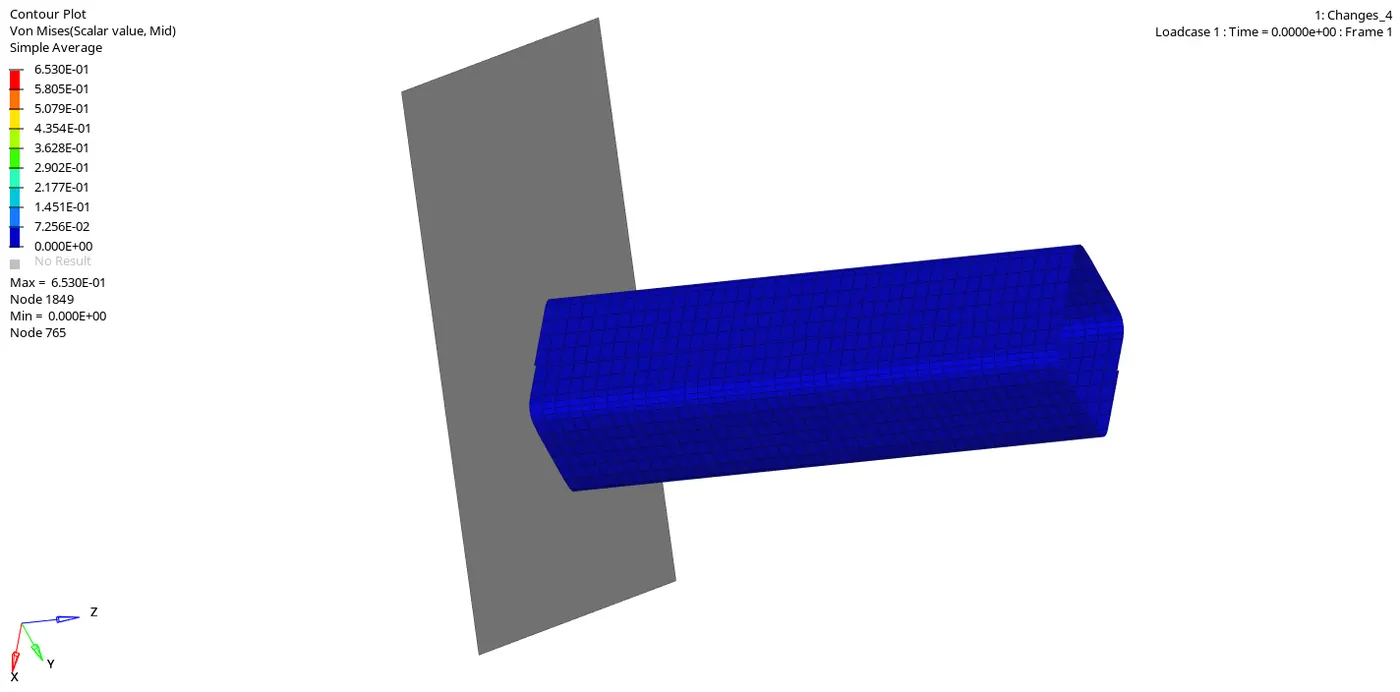 |
|
| 2. | Internal Energy | 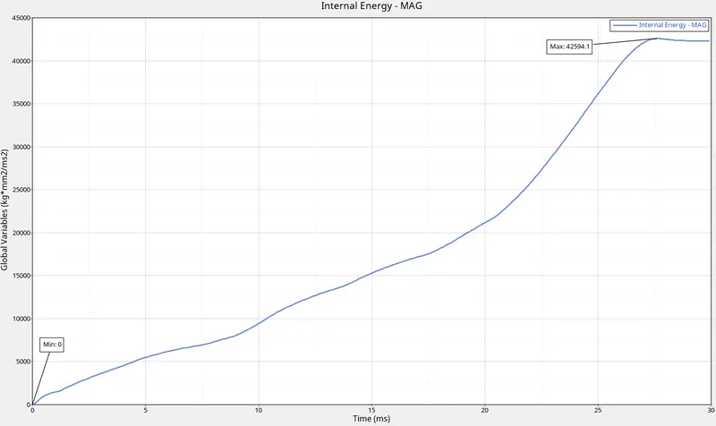 |
|
| 3. | Kinetic Energy | 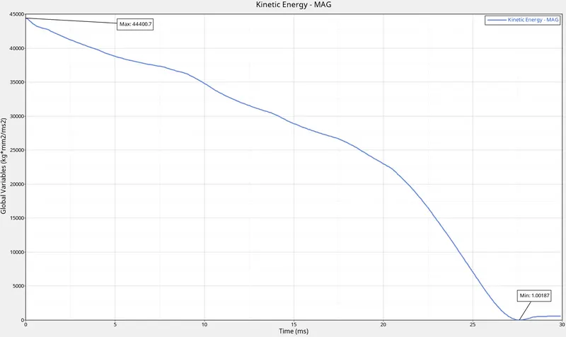 |
|
| 4. | Contact Energy | 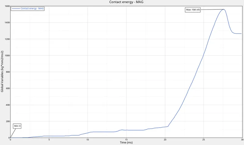 |
|
| 5. | Hourglass Energy | 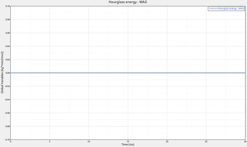 |
|
| 6. | Rigid Wall | 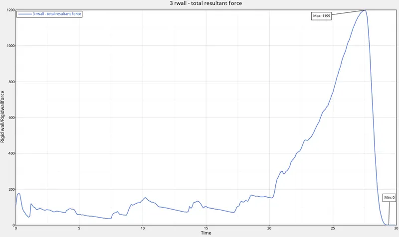 |
|
| 7. | Total Energy | 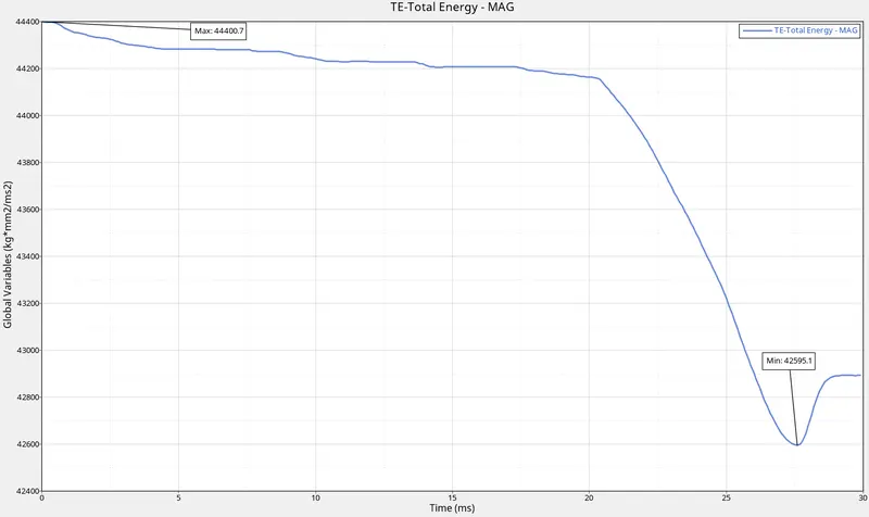 |
|
| 8. | All Graphs | 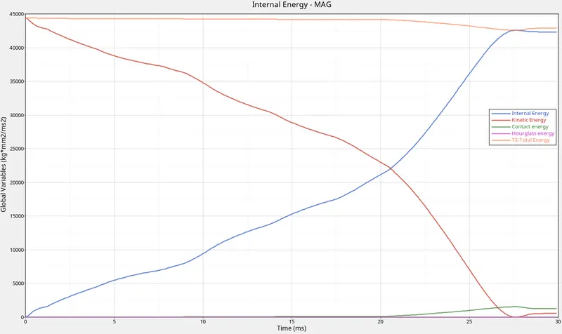 |
|
| 9. | Energy and Mass error | 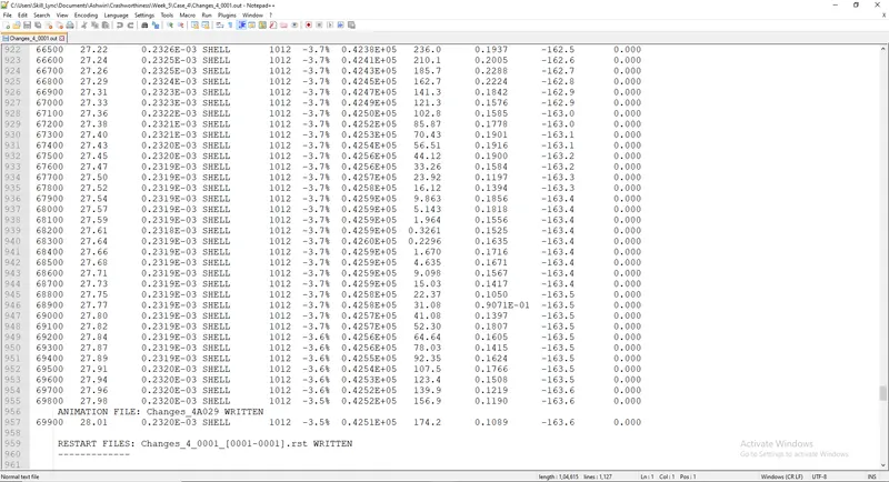 |
|
| 10. | Run Time | 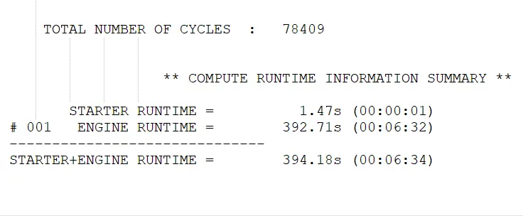 |
|
e) Case 5:
| Sl. No | Name | Image | Observations |
| 1. | Von Mises Stress | 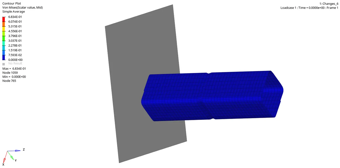 |
|
| 2. | Internal Energy | 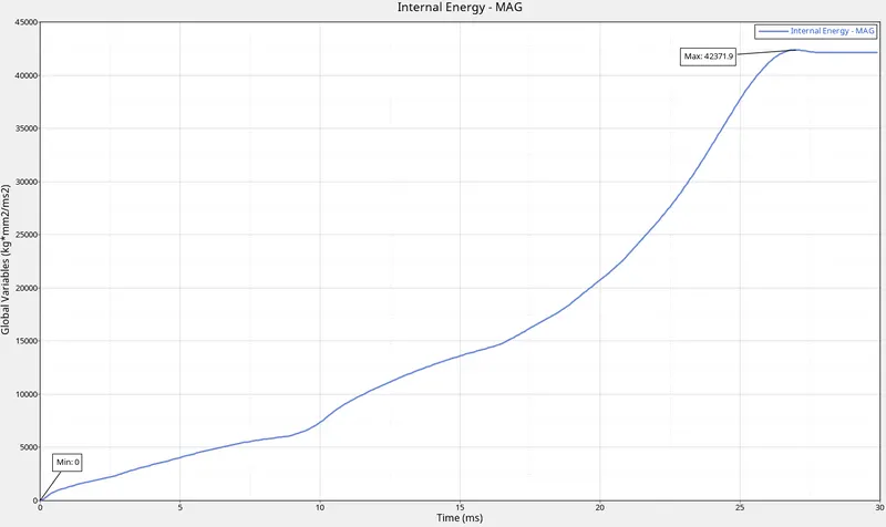 |
|
| 3. | Kinetic Energy | 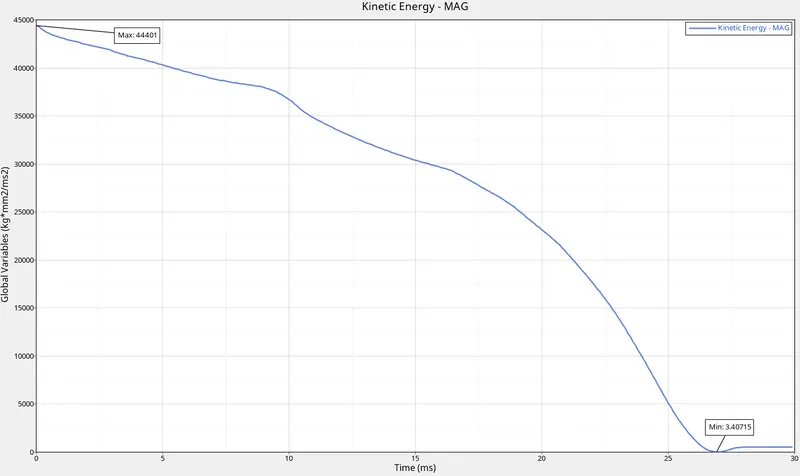 |
|
| 4. | Contact Energy | 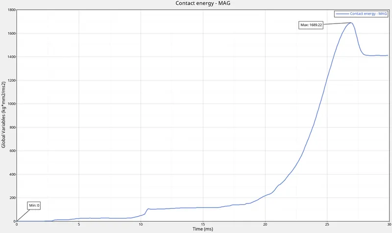 |
|
| 5. | Hourglass Energy | |
|
| 6. | Rigid Wall | 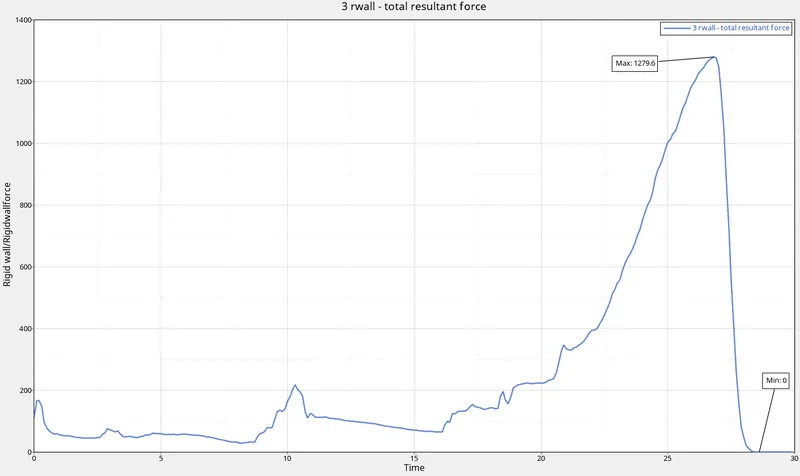 |
|
| 7. | Total Energy | 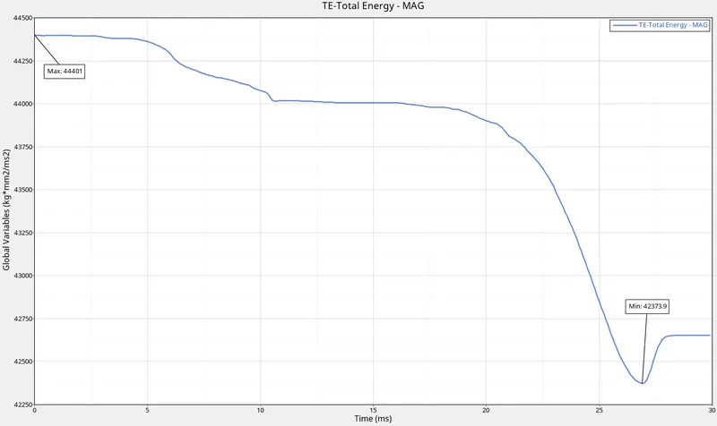 |
|
| 8. | All Graphs | 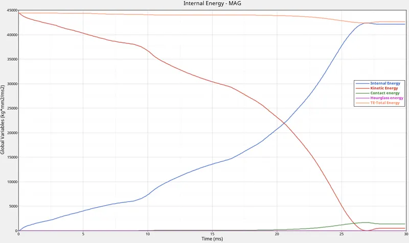 |
|
| 9. | Energy and Mass error | 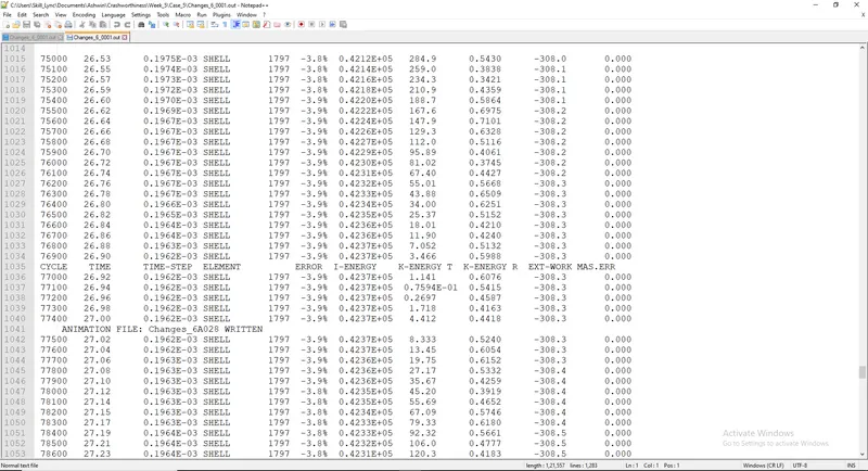 |
|
| 10. | Run Time | 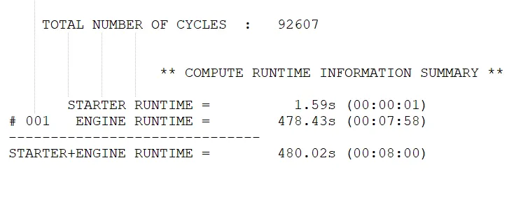 |
|
f) Case 6:
| Sl. No | Name | Image | Observations |
| 1. | Von Mises Stress | 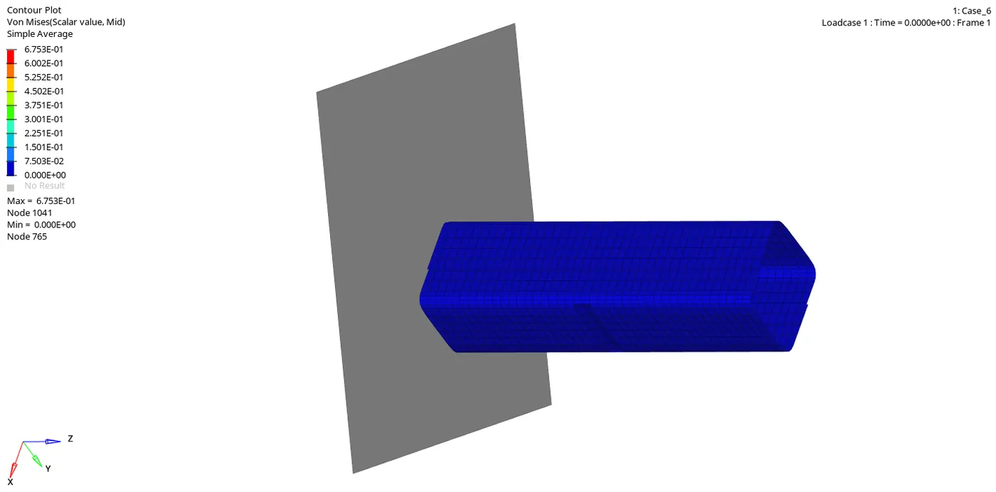 |
|
| 2. | Internal Energy | 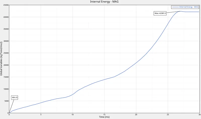 |
|
| 3. | Kinetic Energy | 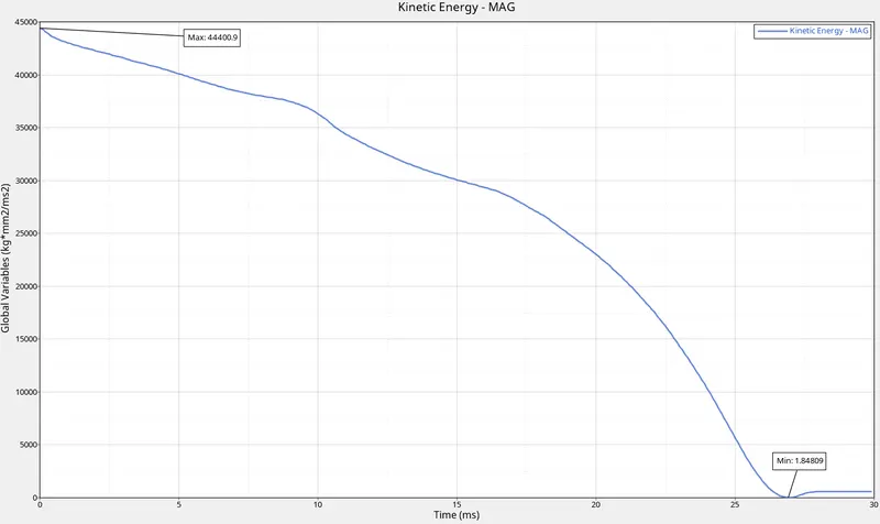 |
|
| 4. | Contact Energy | 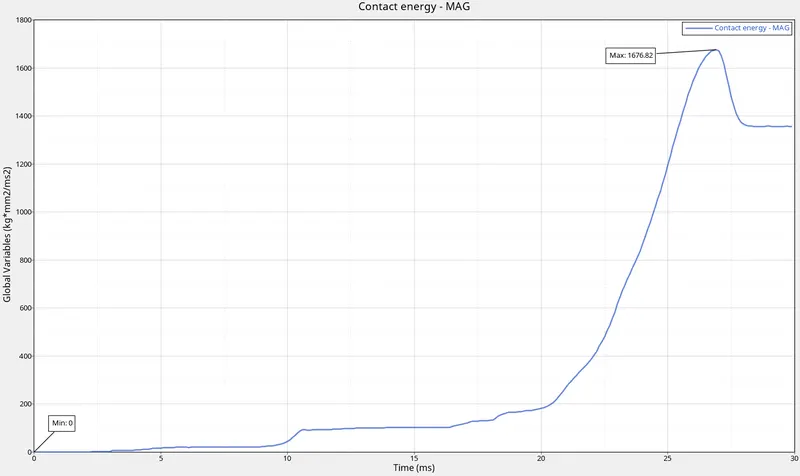 |
|
| 5. | Hourglass Energy | |
|
| 6. | Rigid Wall | 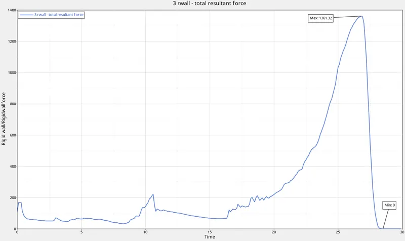 |
|
| 7. | Total Energy | 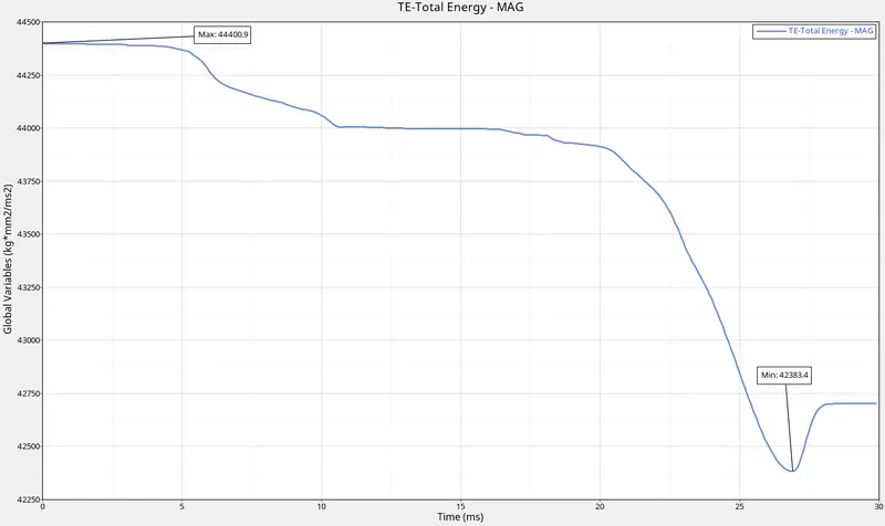 |
|
| 8. | All Graphs | 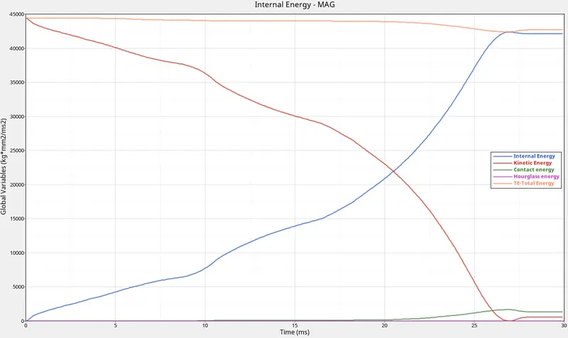 |
|
| 9. | Energy and Mass error | 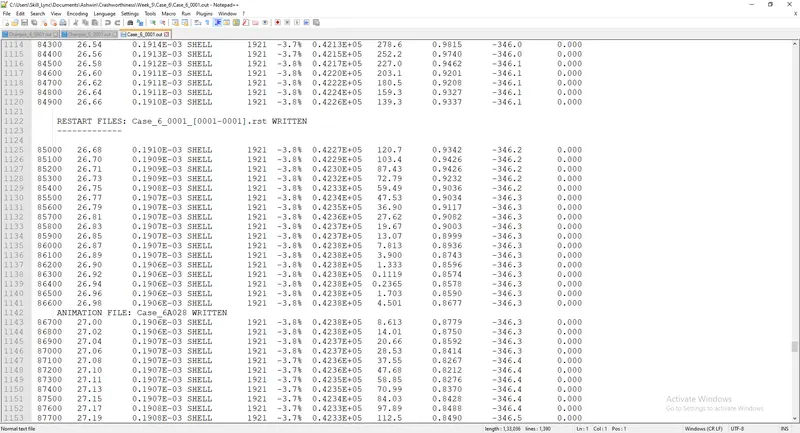 |
|
| 10. | Run Time | 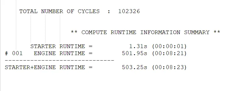 |
|
CONCLUSION:
i) Interface parameters play a vital role in determining the way a component will deform under an applied load.
ii) We used different types of contacts to analyze the deformations of a crush tube.
iii) We also analyzed the deformation and buckling behaviour of the crush tube in the absence of a notch and also using different notch designs.