Meshing of Hood model
OBJECTIVE:
To perform geometry cleanup of the given component and mesh the same while following the strict quality criterias provided.
PROCEDURE:
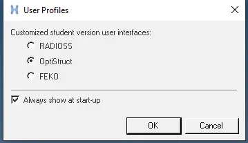
- Select Optistruct from the user interface menu.
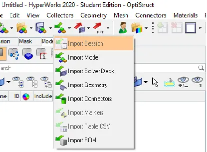
- Click on import -> Import Geometry
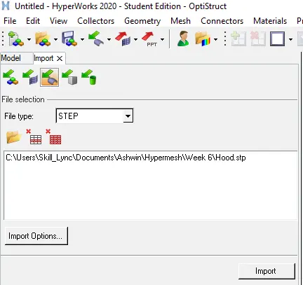
- Change file type to STEP and select the required file and click on import.
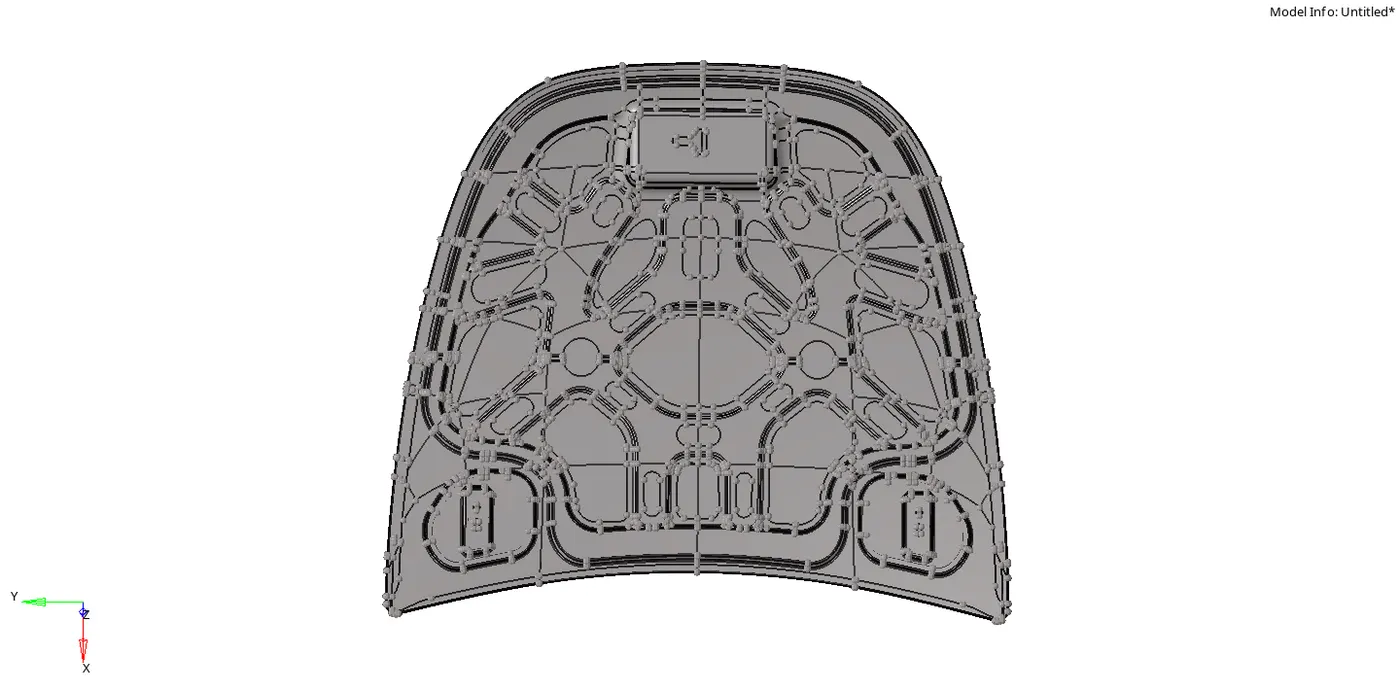
- The following model is obtained:
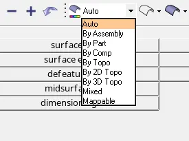
- Change the geometry visualization bar to 'By topo'.
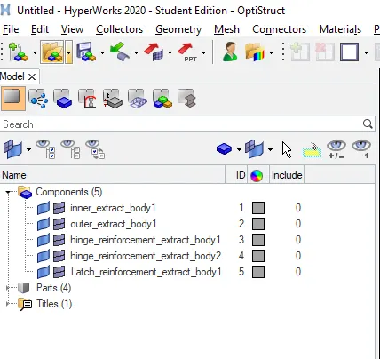
- Upon inspection we can see that the model can be broken down into the following parts:
i) Latch
ii) Hinge 1
iii) Hinge 2
iv) Outer panel
v) Inner pannel
- We have to delete the solids to proceed further.
- To delete click on delete-> solids -> all -> delete entity.

- Upon further inspection we can conclude that the given model is symmetric.
- To save time we can delete half of the model and mesh it.
- Once the meshing is done we can reflect it back to the other side.
- To delete surfaces click on delete -> surface -> select surfaces from one side of the model -> delete entity

(Note: The Latch is not symmetric hence we do not select it for deleting surfaces)
- Before meshing we have to keep the following things in mind:
a)Always start meshing the complex component first.
b) Start meshing from the surface with the most features or the surface with free edges.
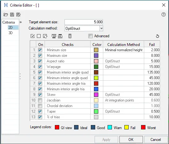
- The quality criteria needed to be followed is listed below:
Target Element Length = 5mm
| S.N | Quality Criteria | Value |
| 1 | Aspect Ratio | 5 |
| 2 | Skewness | 45 |
| 3 | Warping | 15 |
| 4 | Taper | 0.5 |
| 5 | Min. Length | 2mm |
| 6 | Max. Length | 8mm |
| 7 | Min angle Quad | 45 |
| 8 | Max angle Quad | 135 |
| 9 | Min angle Tria | 20 |
| 10 | Max angle Tria | 120 |
| 10 | Tria % | 10 |
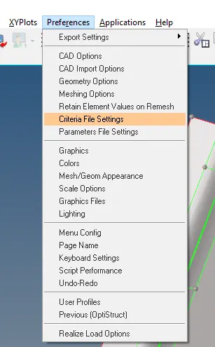
- The save the above criterias click on prefereneces -> criteria file setting -> Enter the parameters -> OK
- The following rules must be followed when it comes to tria management:
a) No trias should be formed on corners or free edges(especially free edges)
b) No opposite trias should be formed
c) Back to back must not be there
d)Rotational quads must not be formed
e) Trias should not share a boundary with feature line
f)Elements must be properly connected
g)Select few elemets and remesh again
- Opposite Trias can be managed by clicking draging trias from quality index.
- To do this click on 2D -> quality index -> clean up tools -> drag trias.

- A good mesh flow can be obtained by clicking on 2D -> smooth(Shift + F12) -> Select the elements -> smooth

- Now we can work on the components individually.
A)Latch:
- Toggle all the surfaces except for Latch
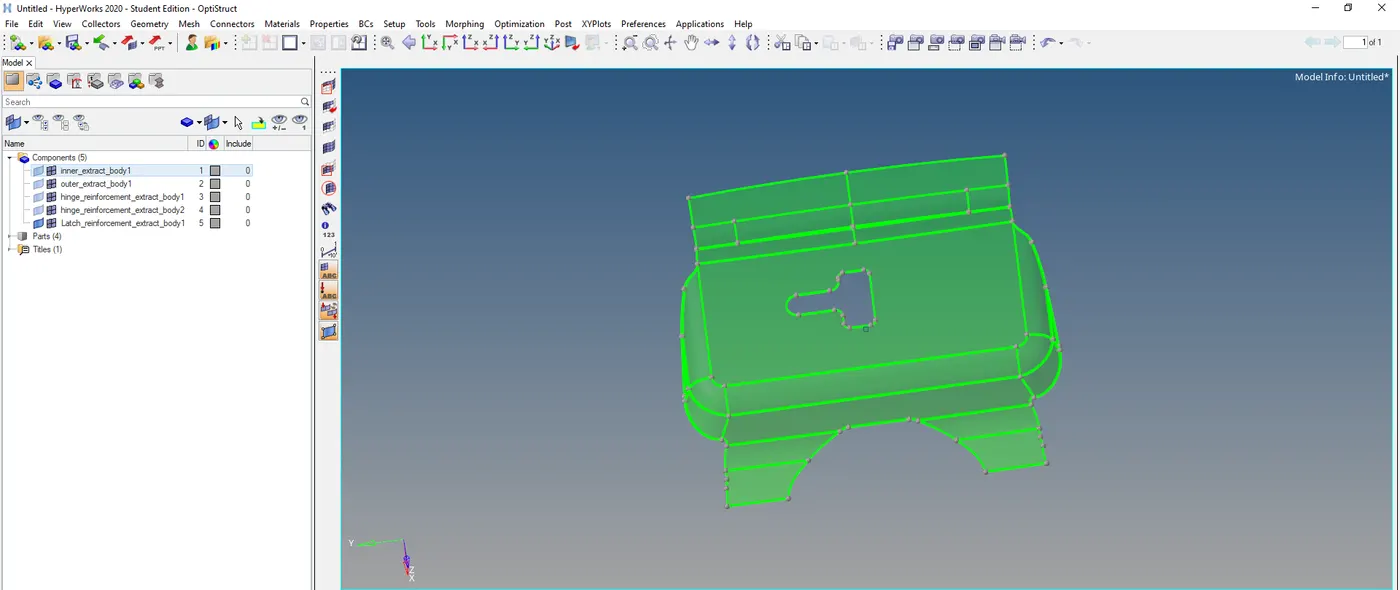
- Now we can extract the midsurface for the latch.
- Click on geom -> midsurface -> auto midsurface -> extraction options -> skin fillet -> auto extraction -> extract.

- By using skin fillet option we were able to capture most of the feature accurately from the parent component.
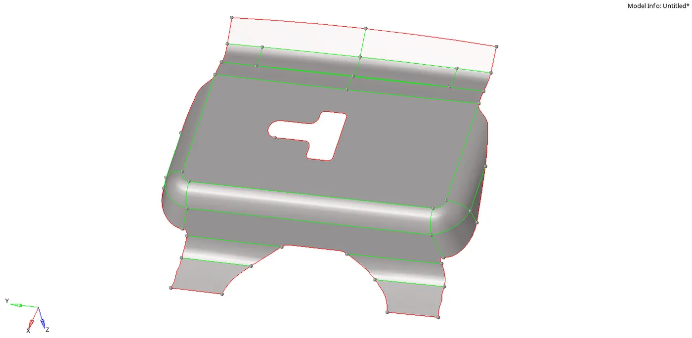
- Since the geometry has many deformations we need to clean it up.
- From the below picture we can see many unwanted lines that are not a part of the feature.
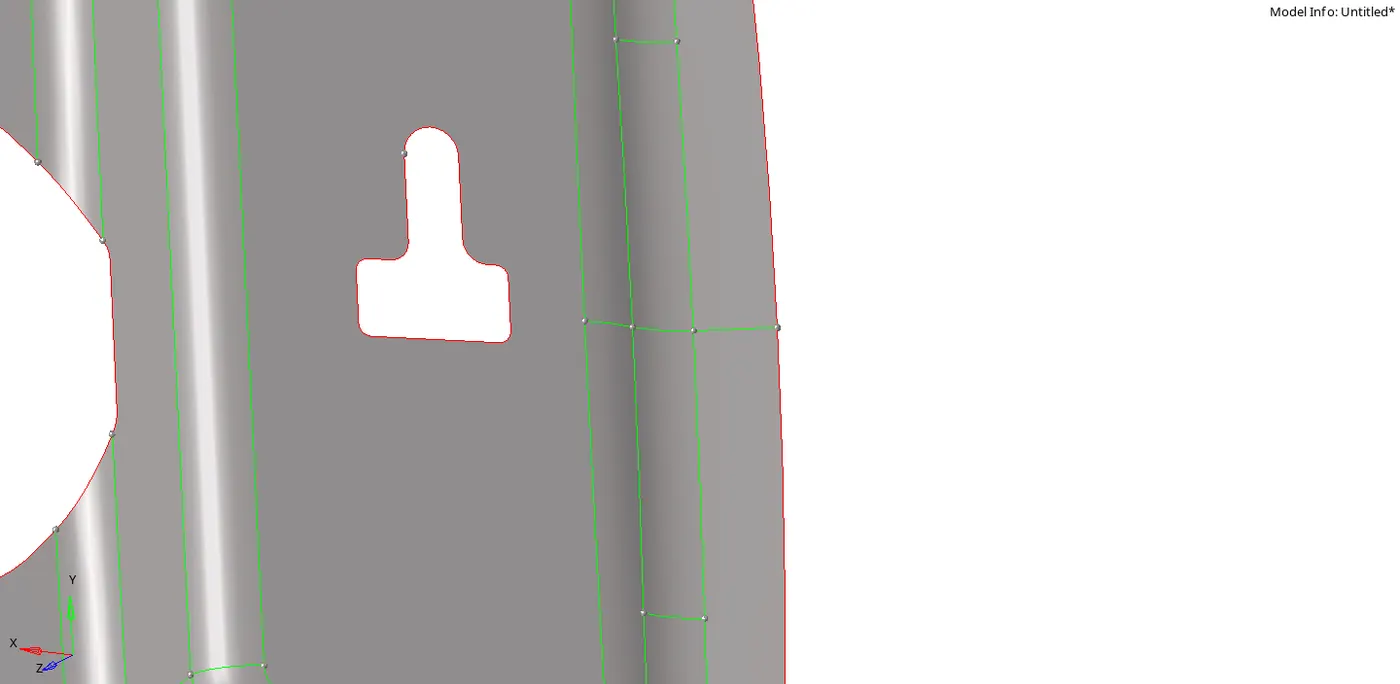
- We can toggle them by clicking on geom -> quick edit (Shortcut for quick edit is F11) -> toggle edges.

- After toggling the unnecessary edges we get the following model:
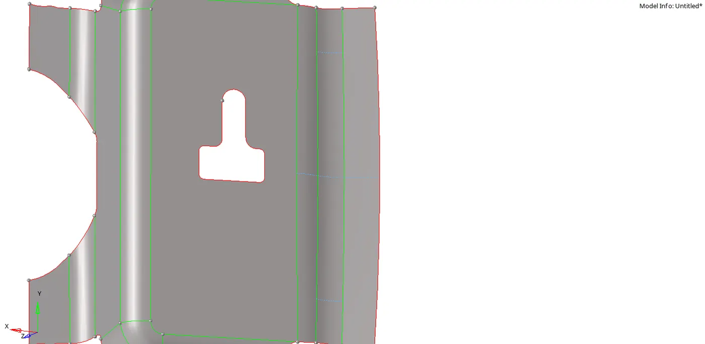
- From the below picture we can see that the the middle fillet will fail for minimum length and therefore we have to get rid of it.
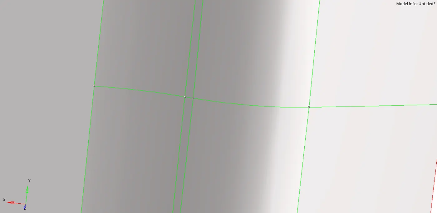
- To solve this we can either toggle one of the edges as shown above or we can click on geom -> quick edit -> replace points -> select the two points you want to merge.
- After replacing the points we get the following model:
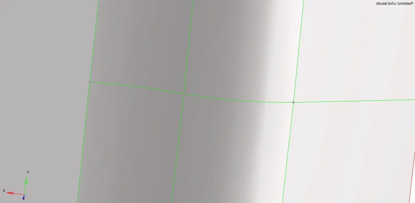
- From the below model we can see that the fillets are complex and excessive trias will be formed.
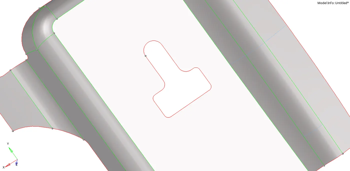
- We can defeature the fillets by clicking on geom -> defeature -> edge fillets -> select the surface -> set minimum radius=1 -> find -> remove

- After defeaturing we get the following model:
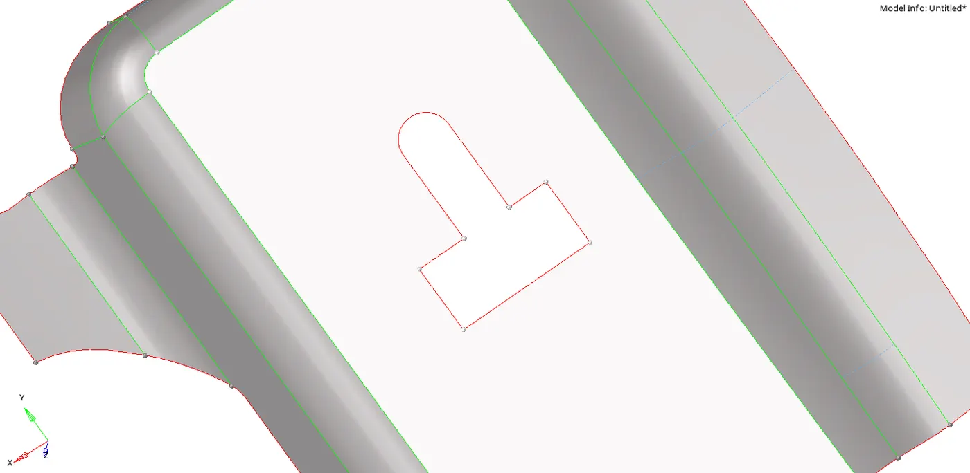
- After cleaning up the geometry we get the following model:
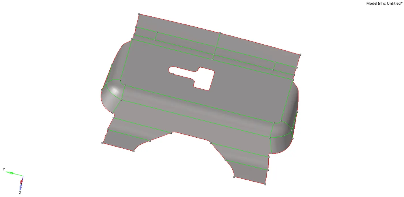
- Now we proceed to meshing the component.
- To mesh click on 2D -> automesh -> select the surface to mesh -> set element size=5 -> mixed elements -> check align and size check box -> mesh

- The final model for latch looks like this:
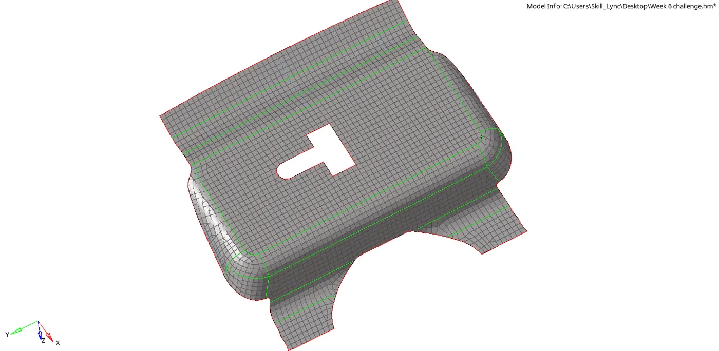
B)Hinge:
- Toggle all the surfaces except for hinge.
- Now we can extract the midsurface for the hinge.
- Click on geom -> midsurface -> auto midsurface -> extraction options -> skin fillet -> auto extraction -> extract.
- Since the geometry has many issues we need to clean it up using the same tools as used before.
- To obtain a good mesh and flow we can provide cuts on the surface.
- This method also helps in eliminating trias.
- To create cuts click on geom ->quick edit -> split surface-line -> select the node and the the edge to be split
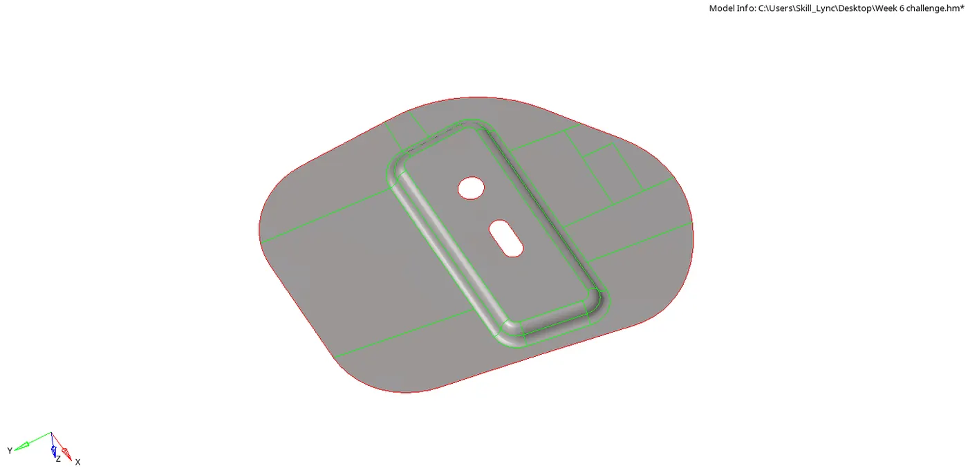
- Now we proceed to meshing the component.
- To mesh click on 2D -> automesh -> select the surface to mesh -> set element size=5 -> mixed elements -> check align and size check box -> mesh
- The final model for hinge looks like this:
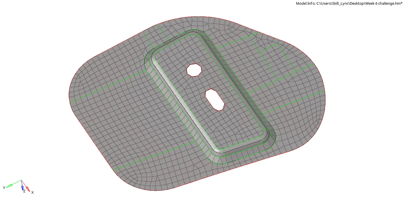
C)Outer Panel:
- Toggle all the surfaces except for outer panel.
- Now we can extract the midsurface for the outer panel.
Click on geom -> midsurface -> auto midsurface -> extraction options -> skin fillet -> auto extraction -> extract.
- Since the panel is symmetrical we can cut it into two parts and delete a side to save time.
- To delete surfaces click on delete -> surface -> select surfaces from one side of the model -> delete entity
- The following model is obtained:
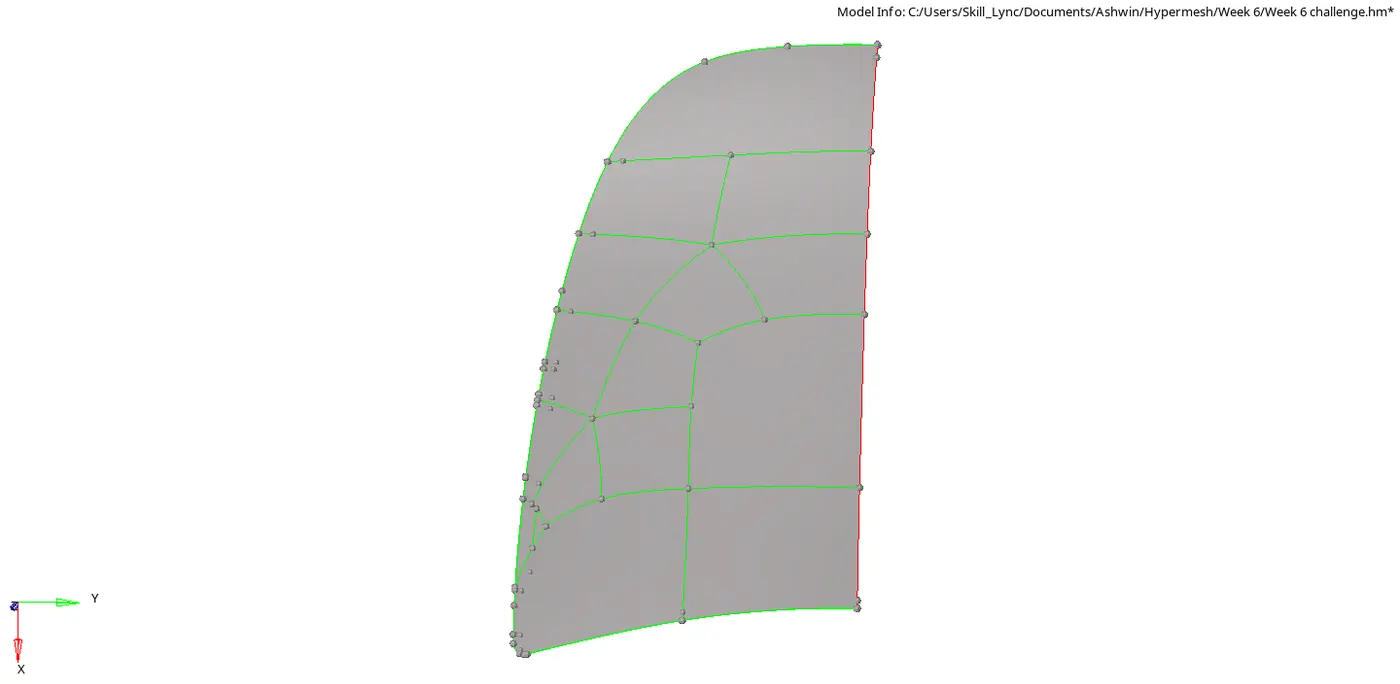
- Since the geometry has many issues we need to clean it up using the same tools as used before.
- To obtain a good mesh and flow we can provide cuts on the surface.
- This method also helps in eliminating trias.
- To create cuts click on geom ->quick edit -> split surface-line -> select the node and the the edge to be split
- After providing the cuts we can mesh it by clicking on 2D -> automesh -> select the surface to mesh -> set element size=5 -> mixed elements -> check align and size check box -> mesh
- Since the model is symmetric about X-axis we have to reflect it about Y -axis.
- We can reflect the elements of the panel by clicking on tools -> reflect -> elements -> duplicate -> y -axis -> select the base node -> reflect.
- We can reflect the surface of the panel by clicking on tools -> reflect -> surface -> duplicate -> y -axis -> select the base node -> reflect.

- The final model for outer panel looks like this:
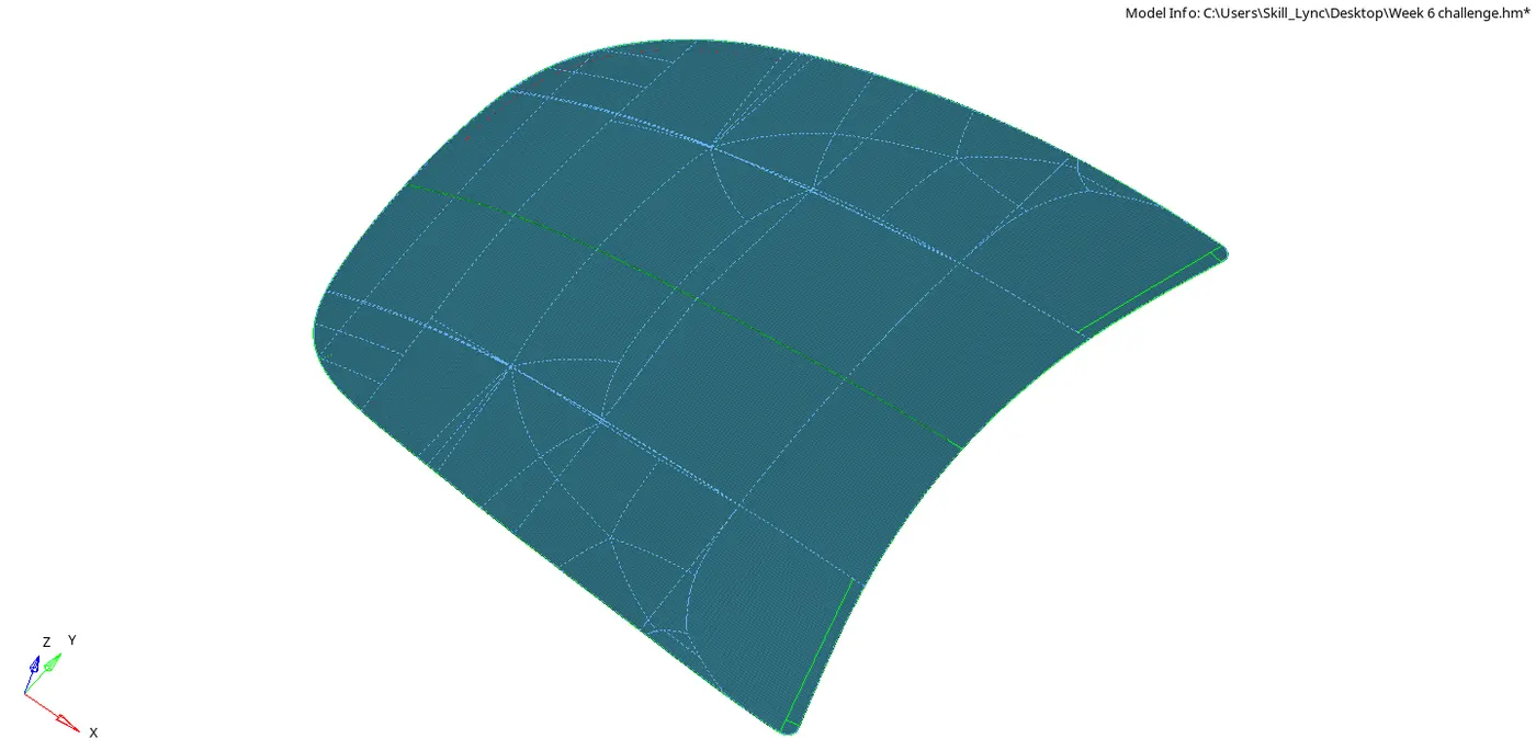
D)Inner Panel:
- Toggle all the surfaces except for inner panel.
- Now we can extract the midsurface for the inner panel.
- Click on geom -> midsurface -> auto midsurface -> extraction options -> skin fillet -> auto extraction -> extract.
- Since the panel is symmetrical we can cut it into two parts and delete a side to save time.
- To delete surfaces click on delete -> surface -> select surfaces from one side of the model -> delete entity
- Since the geometry has many issues we need to clean it up using the same tools as used before.
- To obtain a good mesh and flow we can provide cuts on the surface.
- This method also helps in eliminating trias.
- To create cuts click on geom ->quick edit -> split surface-line -> select the node and the the edge to be split
- The following model is obtained:
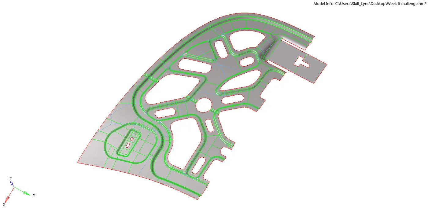
- After providing the cuts we can mesh it by clicking on 2D -> automesh -> select the surface to mesh -> set element size=5 -> mixed elements -> check align and size check box -> mesh
- After meshing the following model is obtained:
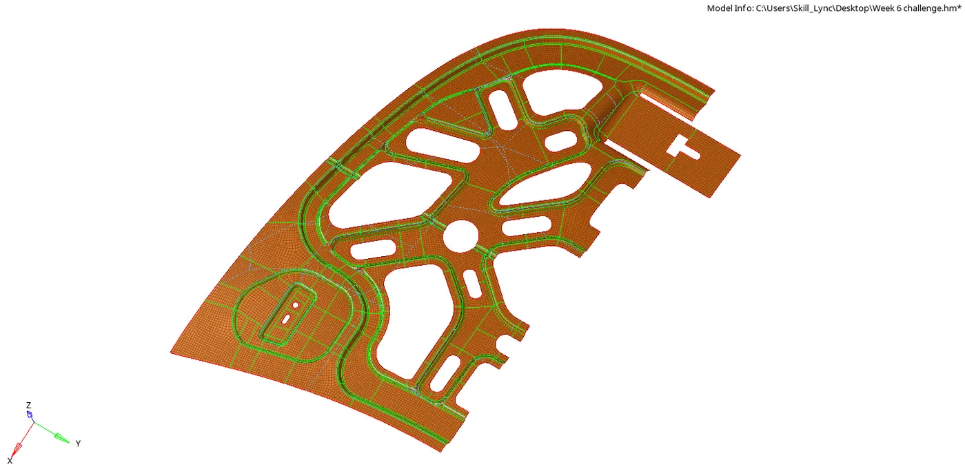
- Since the component has many complex features, few elements might fail for quality and we have to fix those elements.
- From the below image we can see that the element is failing for maximum quad angle:
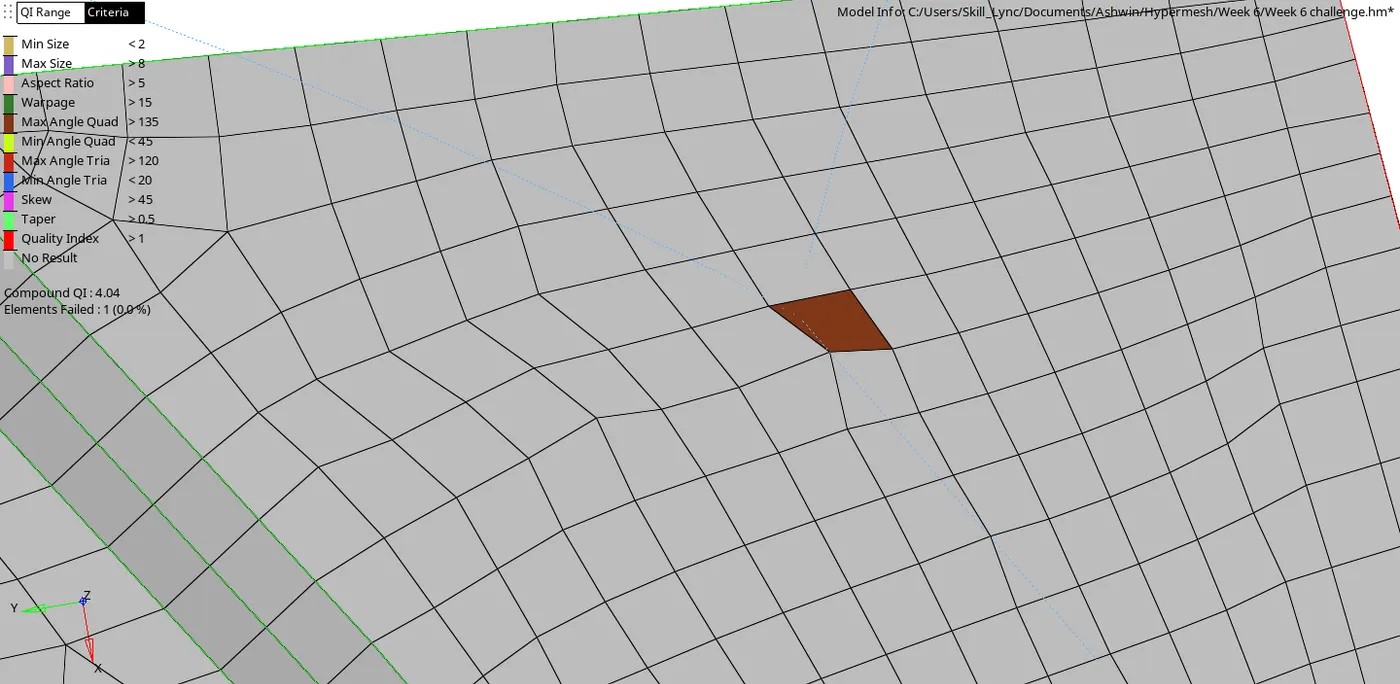
- We can fix it by remeshing or by clicking on 2D -> smooth(Shift + F12) -> Select the elements -> smooth
- After smoothening the following component is obtained:
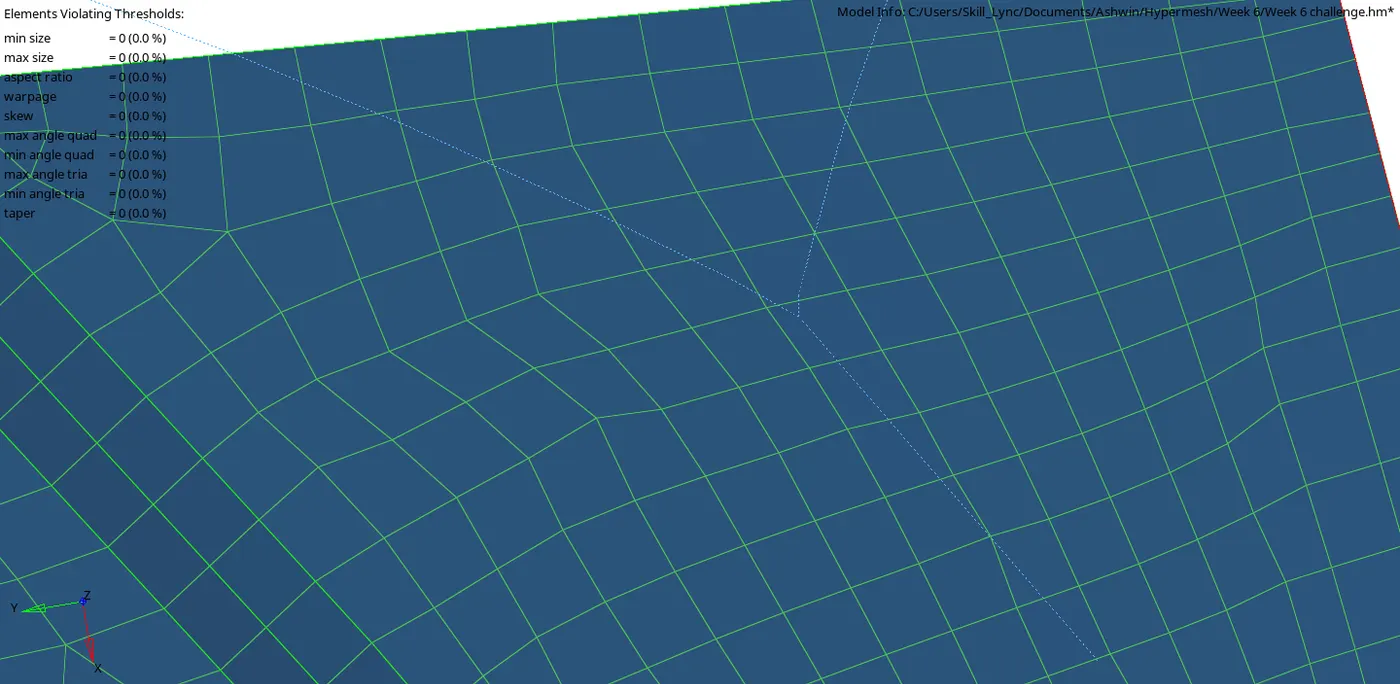
- From the below image we can see that the element is failing for maximum size:
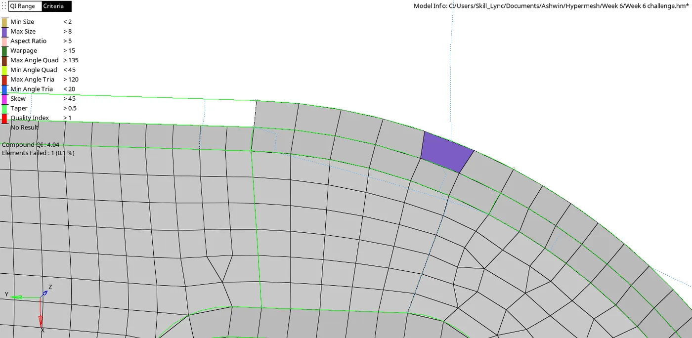
- We can fix it by using smooth or by clicking on 2D -> quality index -> cleanup tools -> element optimize.
- After using element optimize the following component is obtained:
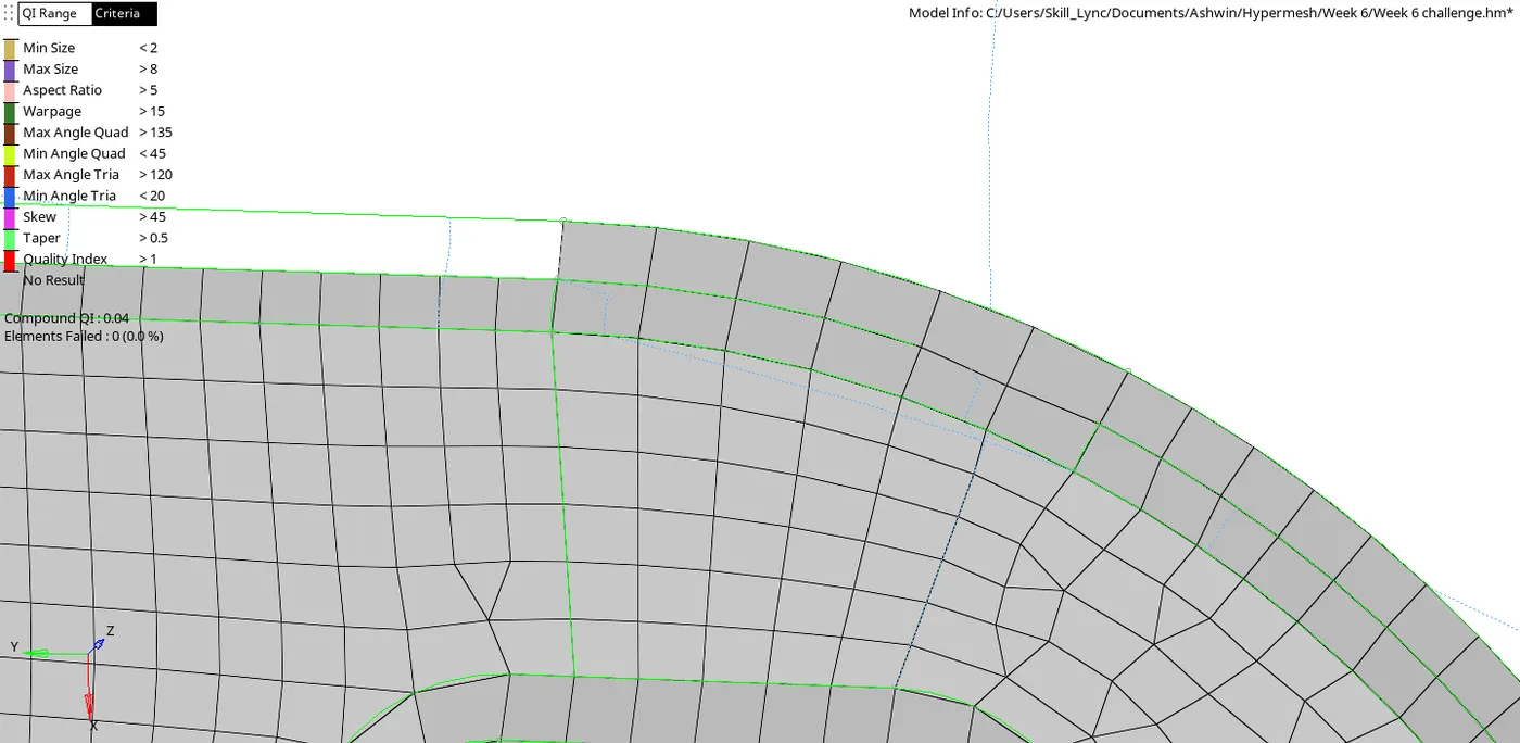
- From the below image we can see that the element is failing for minimum tria angle:
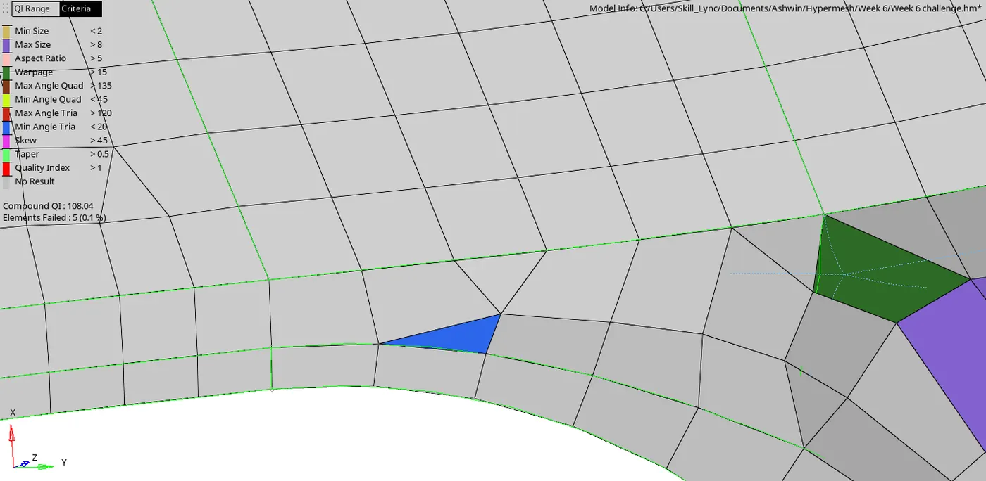
- We fix this issue by remeshing.
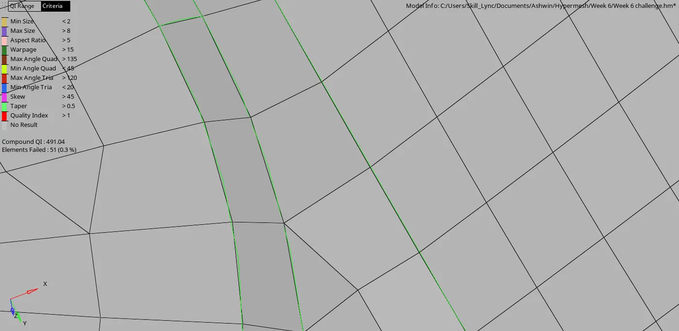
- From the below image we can see that the element is failing for warpage:
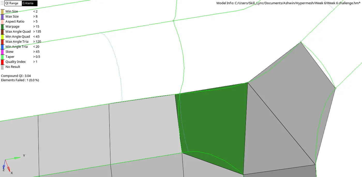
- We can try smooth option or we can translate the node in any direction.
- First we have to check the warpage of the failing element as well as the surrounding elements.
- This can be done by clicking on clicking on tool -> check elements(F10) -> click on the failing element as well as the surrounding elements.
- Now click on Tool -> translate (Shift + F4) -> select the node around which warping happens -> select N1,N2 and N3 nodes around the failing element -> click on 'translate +' or 'translate -' until warpage is gone.
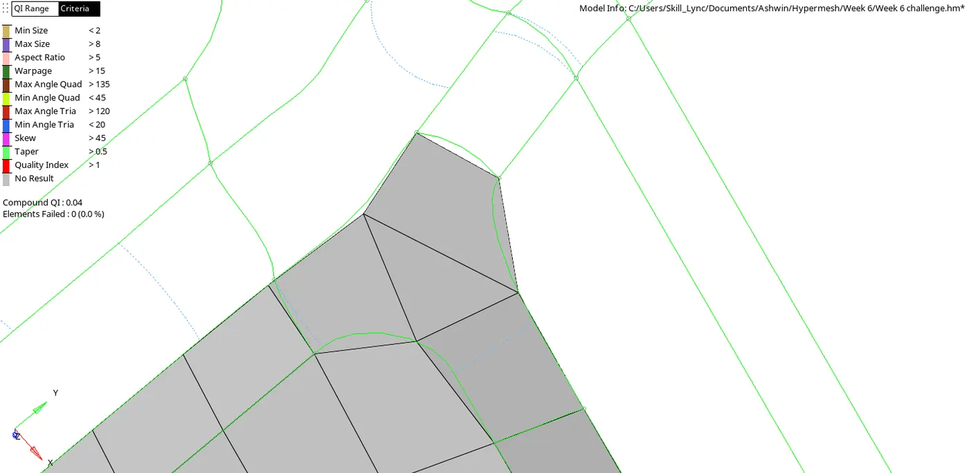
[Note: Select N1,N2and N3 nodes around the element with the least warpage so that the warpage from the failing element can be transferred to it]
- After using various tools to clear all the quality criterias, the following model is obtained after reflecting:
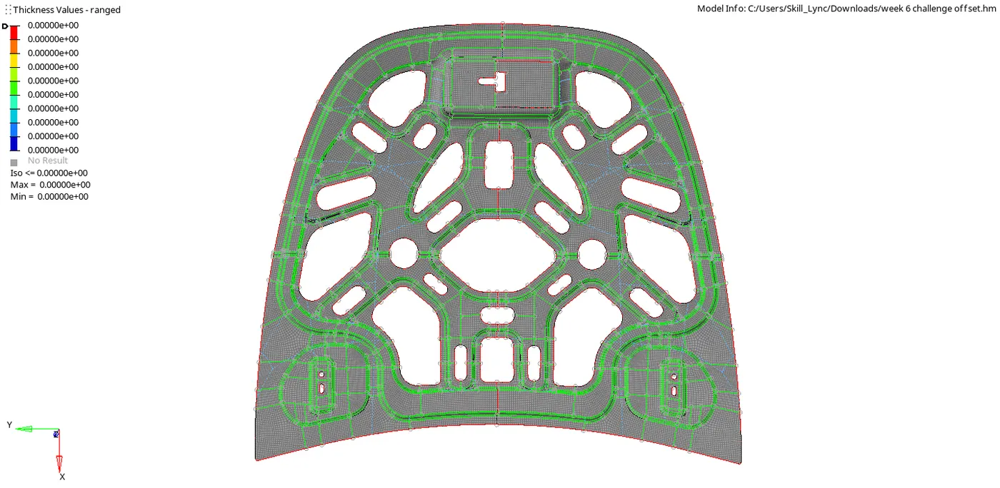
RESULT:
Performed geometry clean up on the given component and meshed the same while maintaining quality criterias and having low tria percentage.