Meshing of brackets and providing cross section to the deployed 1D element
AIM:
To mesh a given component and deploy a 1D element on it and to later provide cross section to the same element and assign properties to it.
PROCEDURE:
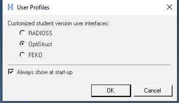
- Select Optistruct from the user interface menu.
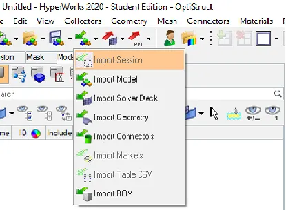
- Click on import -> Import Geometry
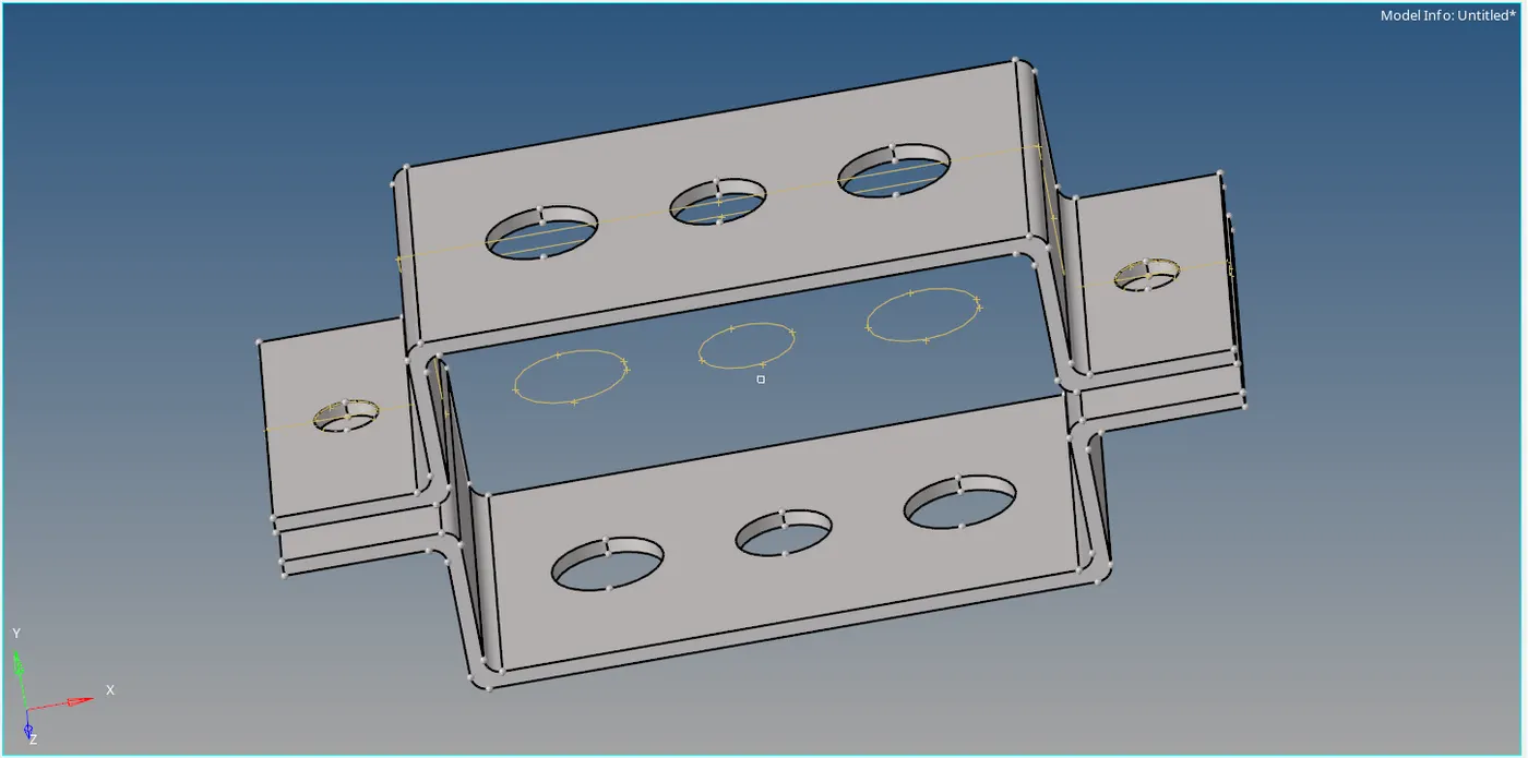
- The following model opens:
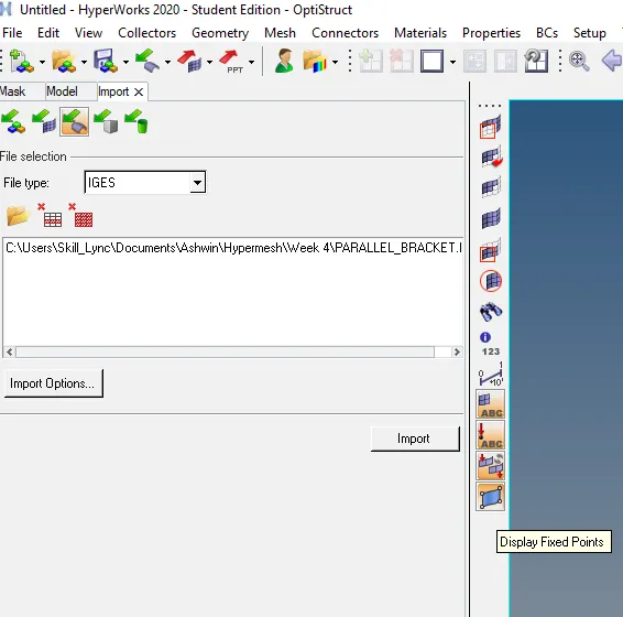
- After inspecting the model click on 'Display fixed points'.
- CLick on 'Geom' -> midsurface -> extract options -> Change to skin offset -> auto extraction -> select the surface -> extract


- Rename the midsurface to 'Bracket 1'.
- Continue the same process to achieve the midsurface for the bottom bracket and rename it to 'Bracket 2'.
- To delete solids, Click on Delete -> -> solids -> Select all -> delete entity

- Since we do not require the surfaces right now we can uncheck them.
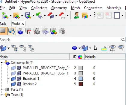
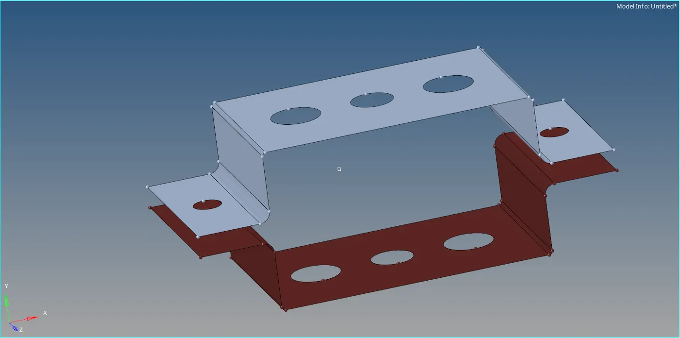
- By using the skin offset option, the mid surface we achieved was able to capture all the fillets.
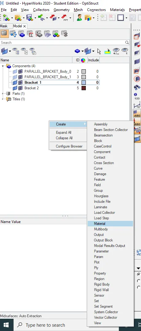
- Right click on tab bar and create material -> rename it to 'Steel'.
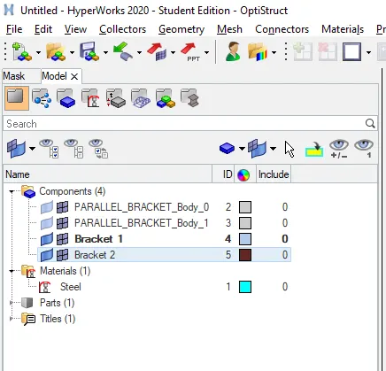
- Right click on tab bar and create property.
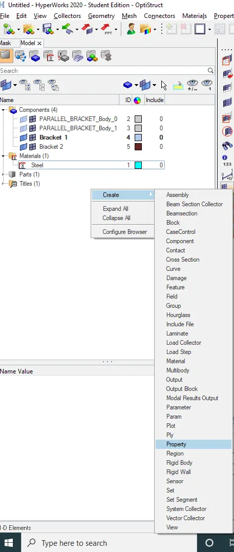
- Create two properties and rename them as 'Bracket 1' and 'Bracket 2'.
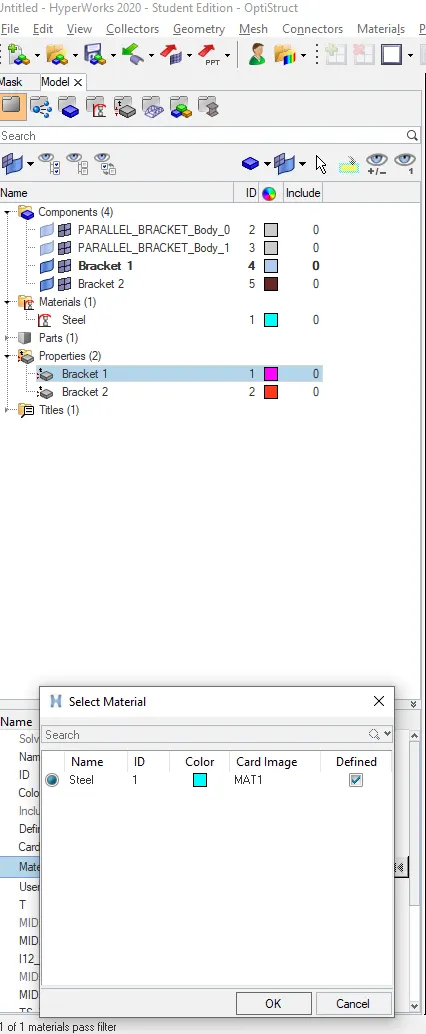
- Click on 'Bracket 1' property -> Thickness=5 ->change material to 'Steel' -> OK
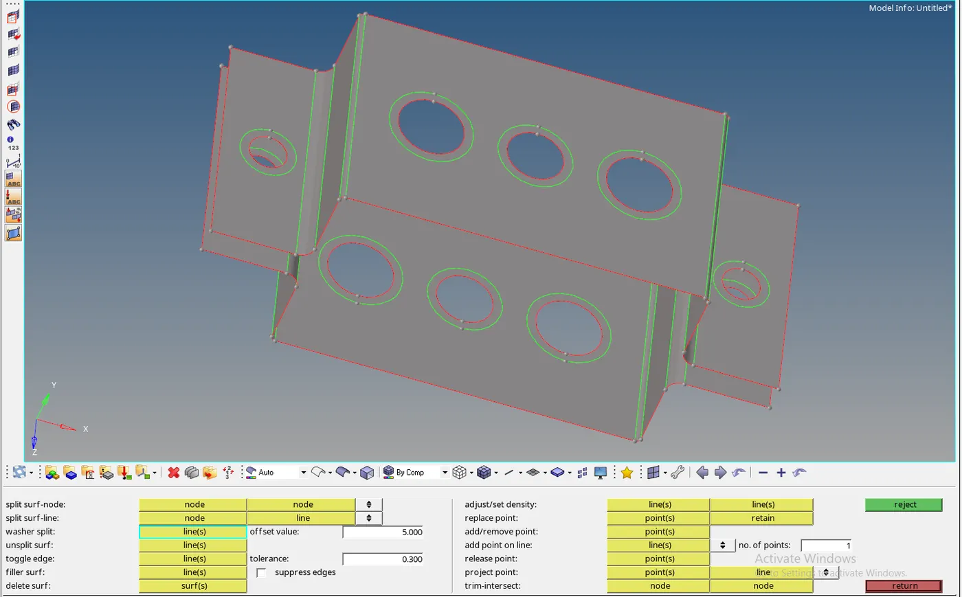
- To add washer splits, go to 'Geom' -> quick edit -> washer split -> Set offset value =5 -> Select all the circles.
- To mesh the model, click on 2D -> automesh -> surface -> displayed -> element size =5 -> mesh.
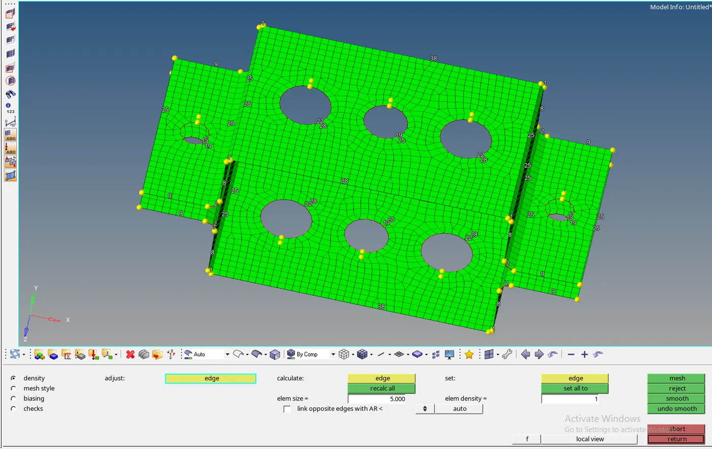
- Since the unequal number of nodes on the hole and washer splits are creating tria elements on the open edge, we have to adjust the number of nodes manually by clicking on them.
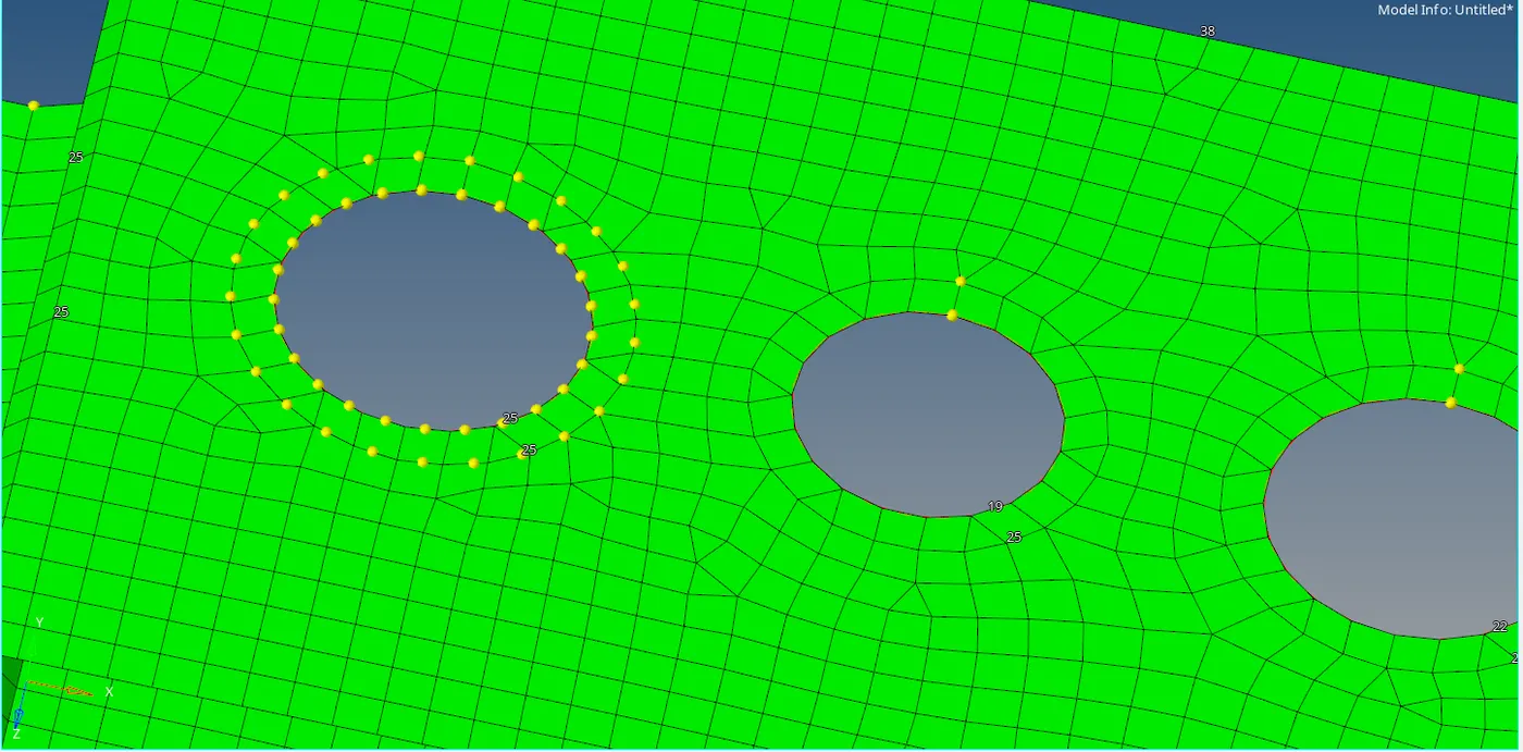
- After adjusting the number of nodes click on mesh again and the final mesh is achieved:
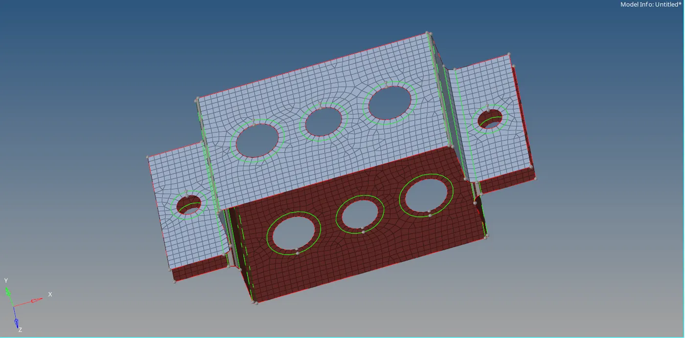
- To create RBE2 and RBE3 links click on 1D.

- Click on rigids(For RBE2) -> Independent variable =Multiple nodes -> dependent variable => Calculate node -> by path -> Uncheck DOF1, DOF2, DOF3 (According to the problem only translational movement is allowed) -> Select all the required nodes -> create
- Continue the same process to get RBE2 link in the bracket 2.
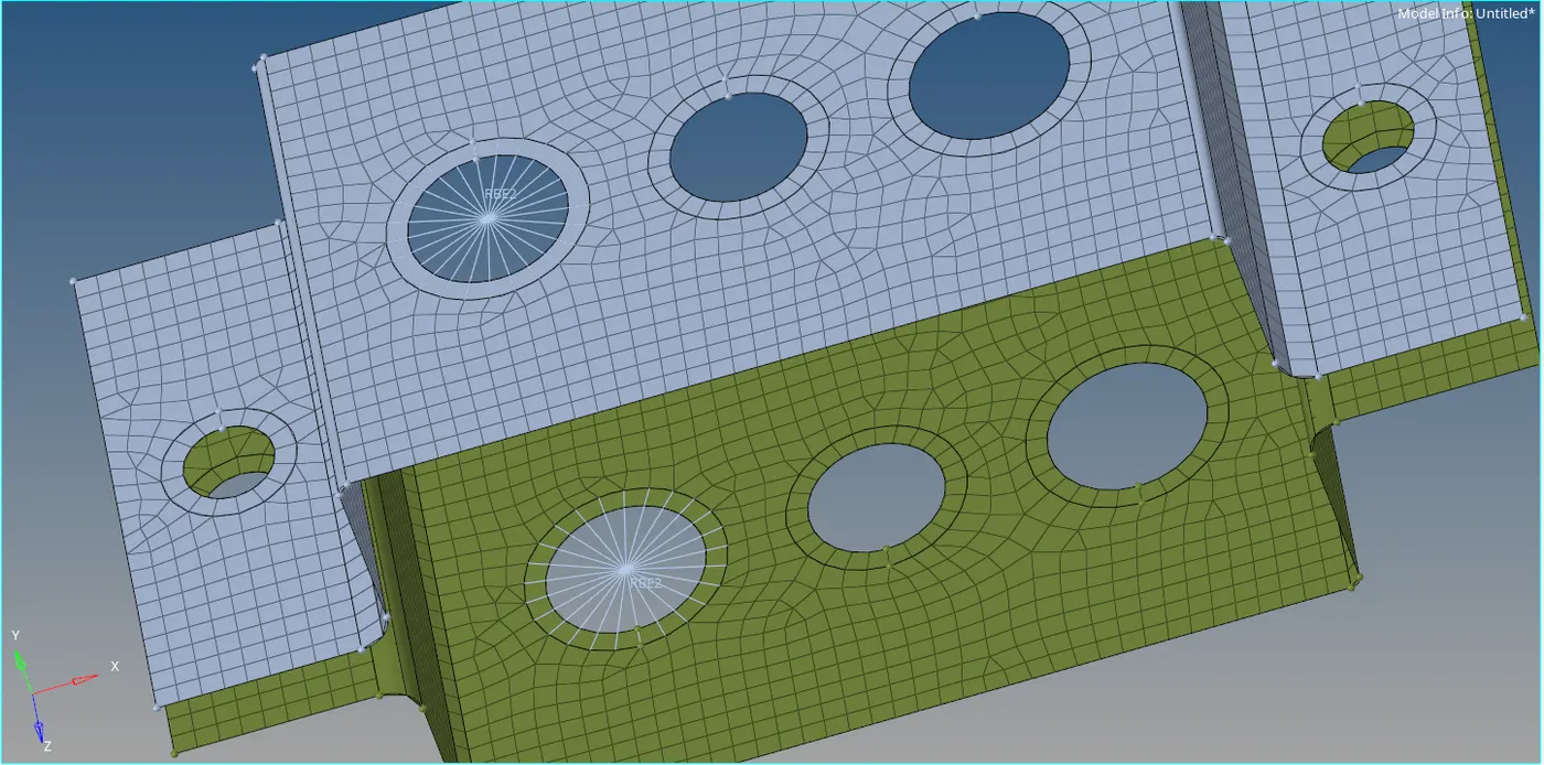

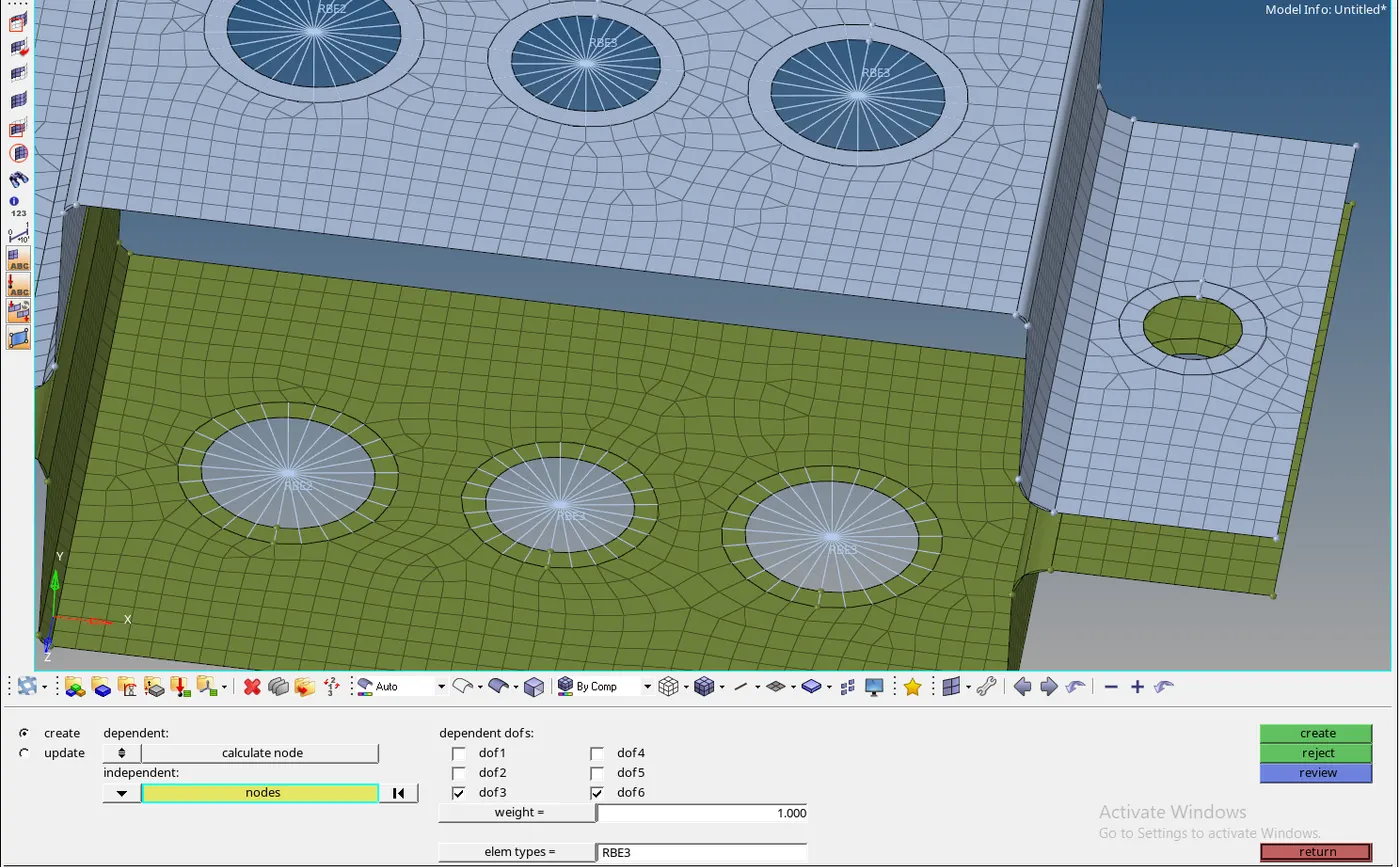
- Click on RBE3 -> dependent =calculate node -> independent = nodes -> by path => Check all DOFs (According to the question all DOFs must be constrained) -> select all the required nodes -> create.
- Continue the same process to get RBE3 link in the bracket 2.
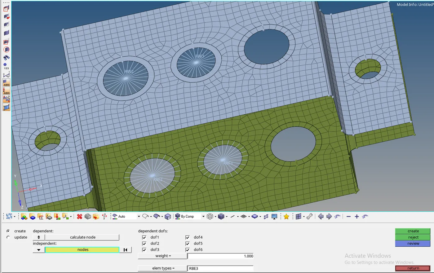
- Click on RBE3 -> dependent =calculate node -> independent = nodes -> by path => Check DOF3 and DOF6 (According to the question, movement is allowed only in X- axis and Y-axis) -> select all the required nodes -> create.
- Continue the same process to get RBE3 link in the bracket 2.
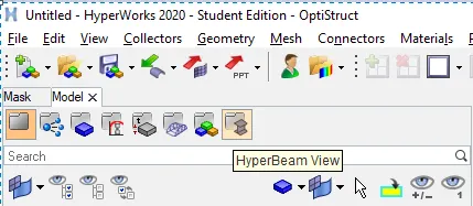
- Click on hyperbeam view on the view bar.
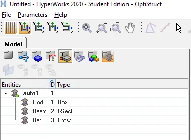
- Create -> standard section -> hypermesh -> thin walled box. Rename this to Rod and give the required dimensions.
- Create -> standard section -> hypermesh -> Standard I section. Rename this to Beam and give the required dimensions.
- Create -> standard section -> optistruct -> Cross. Rename this to Bar and give the required dimensions.
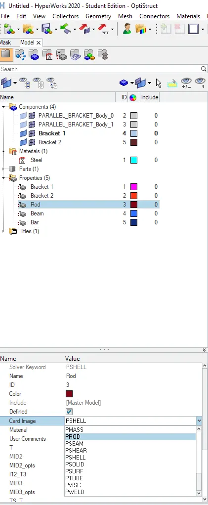
- Click on model view -> Create property -> Rename it to Rod -> card image=PROD -> Material=Steel -> Beam section=Rod ->OK
- Click on model view -> Create property -> Rename it to Beam -> card image=PBEAM -> Material=Steel -> Beam section=Beam ->OK
- Click on model view -> Create property -> Rename it to Bar -> card image=PBAR -> Material=Steel -> Beam section=Bar ->OK
- To create rods, click on 1D -> rods -> select the two centre nodes between RBE2 links -> elem types =CROD ->property=rod-> Click on Tab button.
- To create beams, click on 1D -> bars -> select the two centre nodes between RBE3 links -> elem types =CBEAM ->property=beam -> Select two nodes on the plane -> Click on Tab button.
- To create bars, click on 1D -> bars -> select the two centre nodes between RBE3 links -> elem types =CBAR ->property=bar -> Select two nodes on the plane -> Click on Tab button.


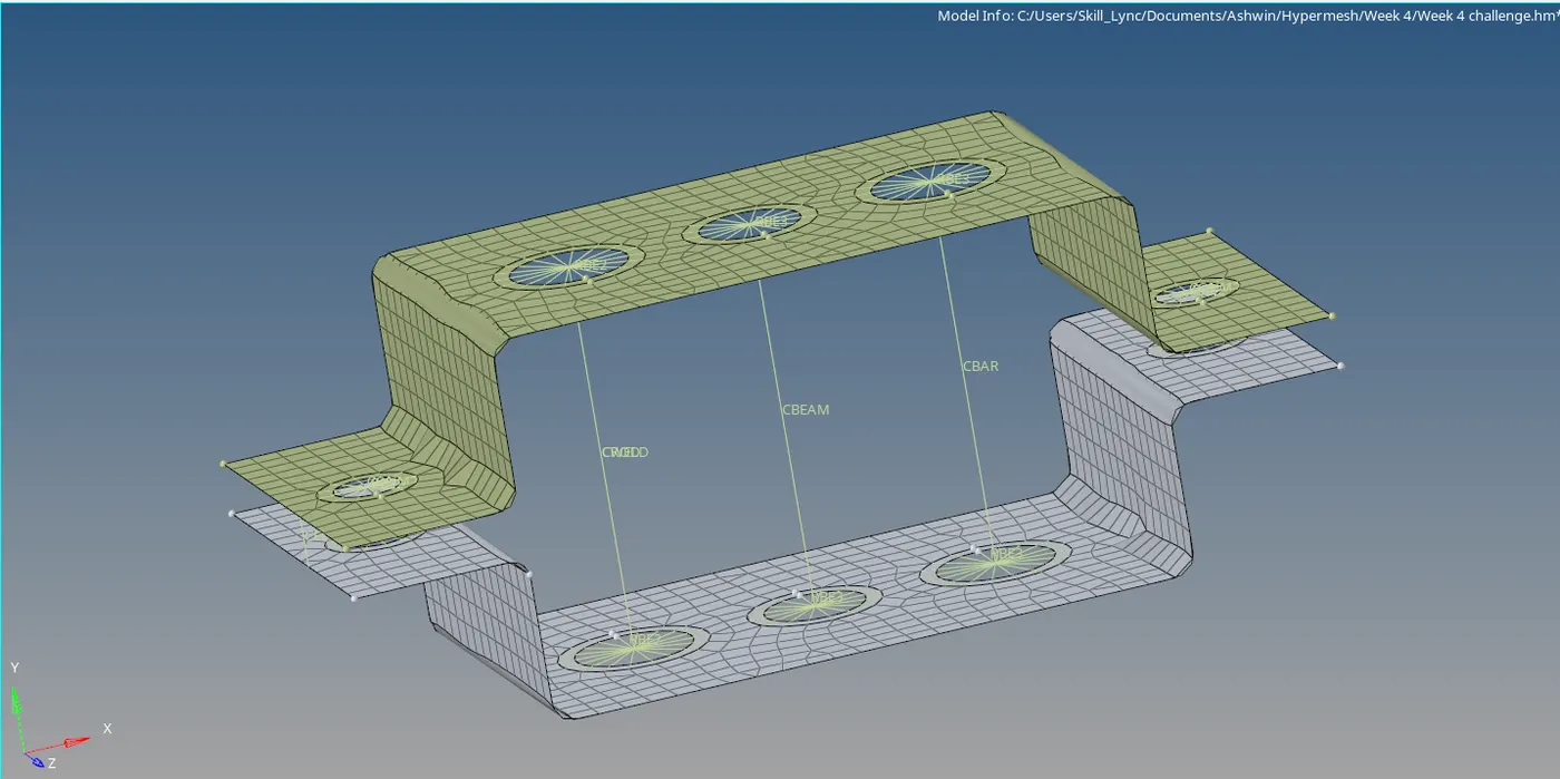
- To create RBE2 links on bolt holes, Click on rigids(For RBE2) -> Independent variable =Multiple nodes -> dependent variable => Calculate node -> by path -> Define any DOF -> Select all the required nodes -> create
- Continue the same process to get RBE2 link on bracket 2 and on the other side.
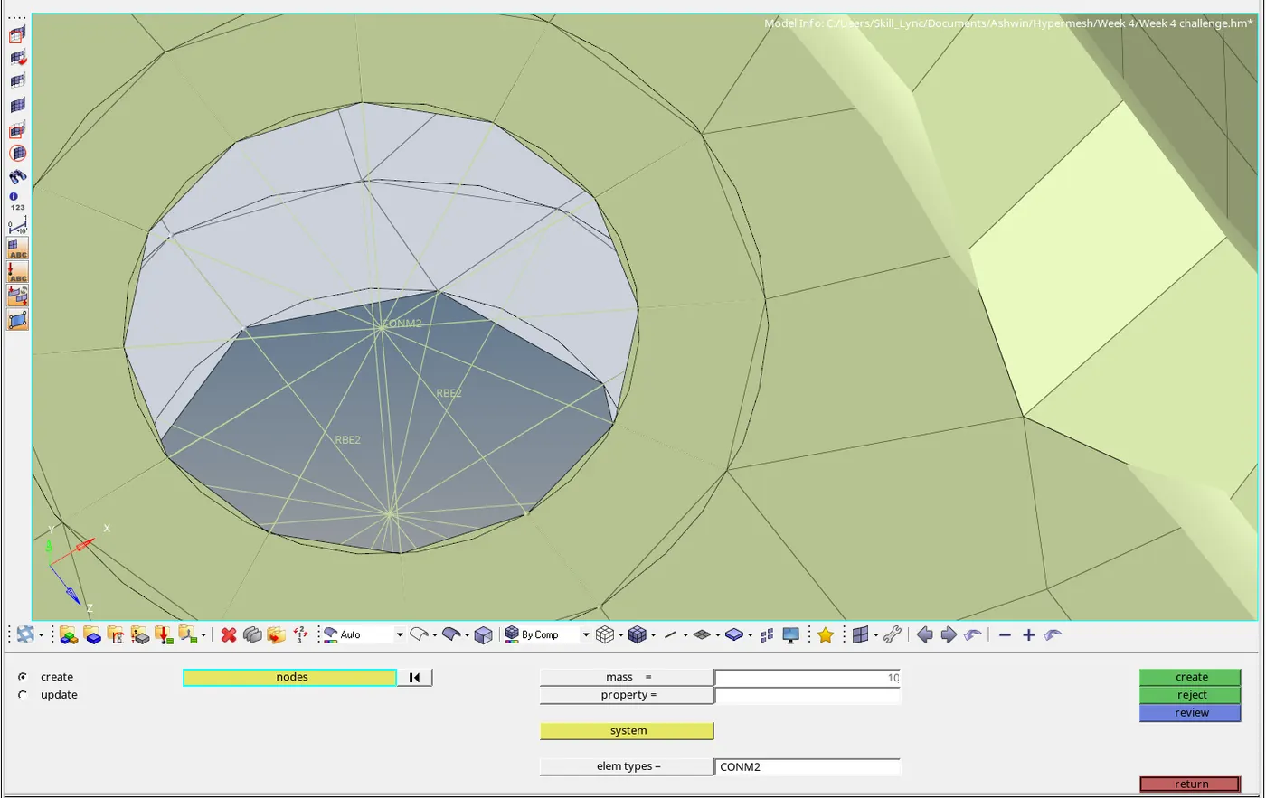
- To get a mass on a node on either side of bracket 1(for bolt hole) click on 1D -> Masses -> select node -> magnitude=10 -> create
- To implement spring elements click on 1D->springs -> select two nodes.
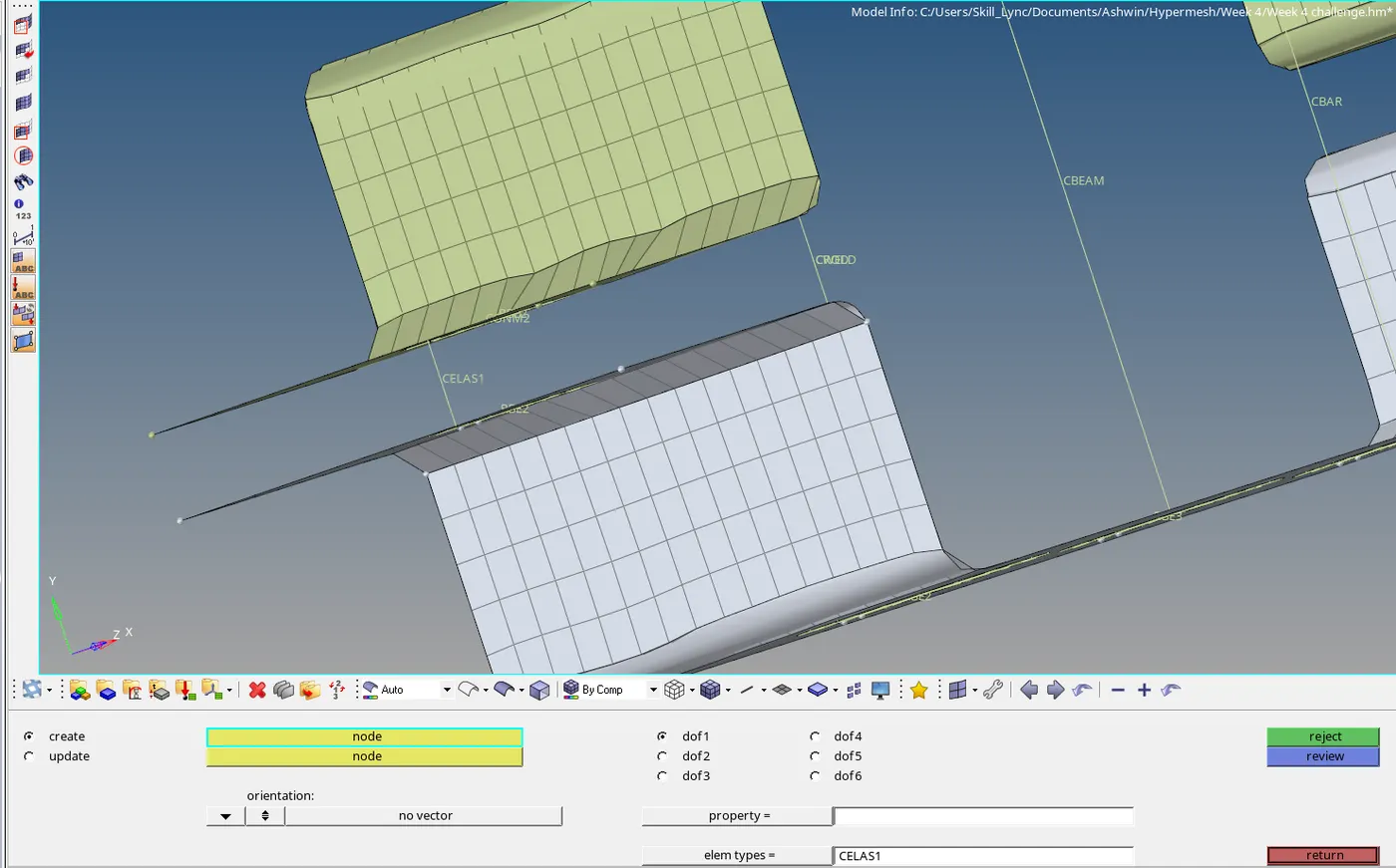
- Repeat the process on the other side as well.
FINAL CAD MODEL:
- Click on 1D Detailed Element Representation from Visualization bar.
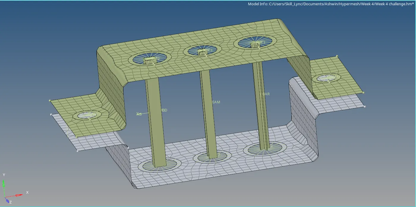
CONCLUSION:
Learnt how to provide midsurfaces to a component and then deploy 1D elements to it. Learnt how to add cross section to the same element using hyperbeam view and assign material and properties to it.