Connectors in Hypermesh
OBJECTIVE:
To create appropriate connectors between meshed surfaces and realize them.
PROCEDURE:
I) Pre-Requisites:
- Connectors are geometric entities which are primarily used to represent CAD geometric connections in FEA.
- Connectors can be created as a spot weld, seam weld, adhesive, bolts, or masses.
- Successfully created connectors that establish a proper connection between two components are called realized connectors.
- Realized connectors are represented in green, unrealized connectors are represented in yellow and failed connectors are represented in red.
- The two main types of welds that are widely used are:
a) Spot Weld:
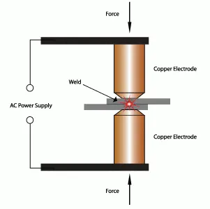
i)Spot weld is a type of resistance welding.
ii) It uses two copper alloy electrodes to concentrate welding currents into a small area which creates welds at regular intervals on overlapping pieces of metal.
iii) It is used for sheet metals with a thickness of 0.5mm to 3 mm.
b) Seam Weld:
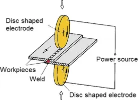
i) Seam weld is also a type of resistance welding.
ii) Seam weld uses a rotating wheel electrode that produces a rolling resistance weld.
iii)It is a continuous weld along a joint as it is forged due to the heat and pressure applied.
iv) This produces a very sturdy weld.
II) Initial Setup:
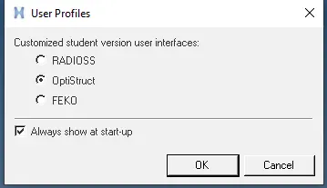
- Select Optistruct from the user interface menu.
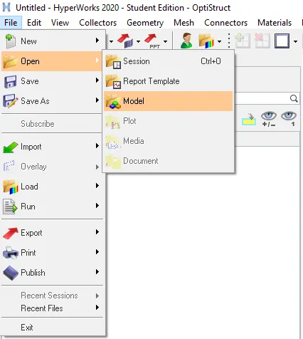
- Click on File -> Open ->Model -> Select the file -> Open.
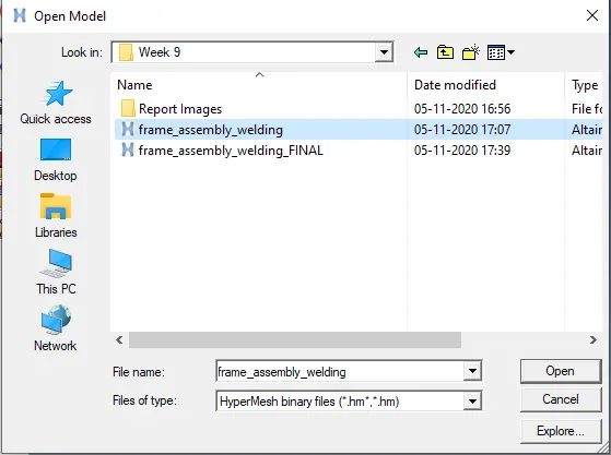
- The following model opens up:
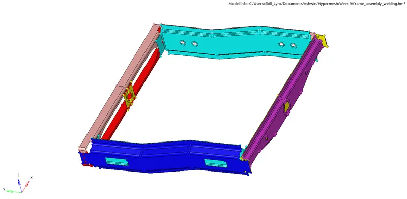
III) Connections:
a) Right_Rail_2 & Front_truss_1 using Seam-Quad(angled+capped+L):
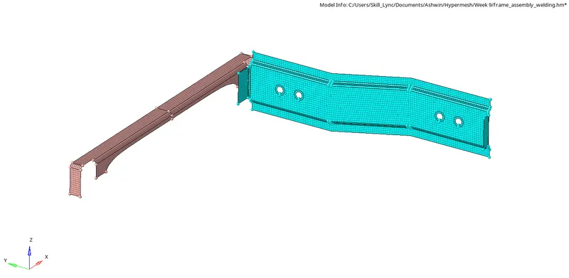
i) To mesh the given components, click on 2D -> Automesh -> Select the surface -> Element Size= 6 -> Mesh Type= Mixed -> Check Align and Size boxes under Flow -> Mesh.

ii)The following mesh is obtained:
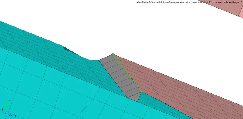
iii)To create a seam connection, click on 2D -> Connectors -> Seam -> Create -> Type= Seam-Quad(Angled+Capped+L) -> Spacing = Element size =6 -> Select the lines between which connections must be established -> Create.

iv) The realized connector is shown below:
v) Since connections are established between two meshed components, there is a chance that the mesh around the connection gets distorted.
vi) Such a distortion is shown below:
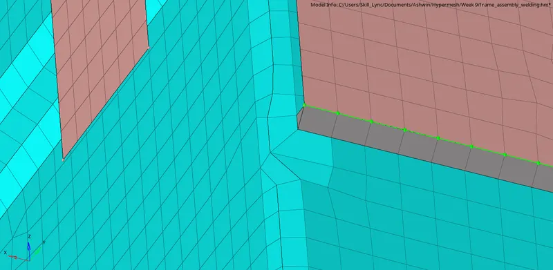
vii) To obtain a better mesh flow, click on 2D -> Smooth -> Select the elements -> Iteration =100 -> Smooth

[Note: Shortcut for Smooth operation is Shift + F12]
[Note: Continue clicking on smooth until the Largest displacement on final iteration on the status bar reaches 0]
viii) We can also align the nodes by clicking on Geom -> Node Edit -> Align node -> Select two end nodes for reference -> Select the nodes that need to be aligned with the previously selected end nodes -> Align.

[Note: Shortcut for Align node is F7]
ix) The result of using the above techniques are shown below:
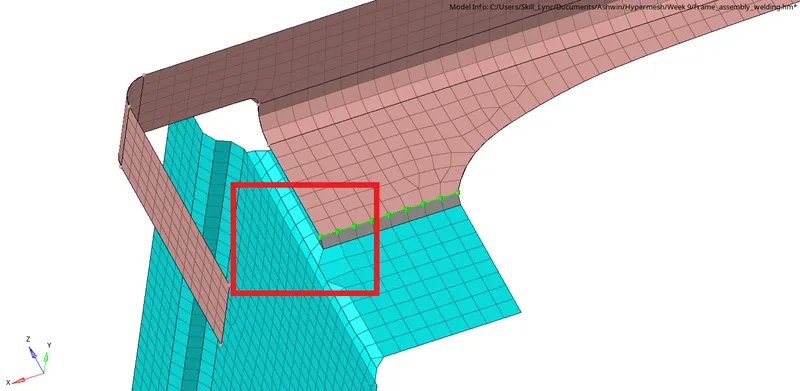
b) Left_Rail_2 & Front_truss_1using Quad elements:
i) To mesh the given components, click on 2D -> Automesh -> Select the surface -> Element Size= 6 -> Mesh Type= Mixed -> Check Align and Size boxes under Flow -> Mesh.
ii) The following mesh is obtained:
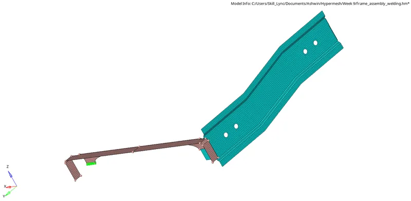
iii) To create a seam weld(quad element connection), click on 2D -> Connectors -> Seam -> Create -> Type= Quad -> Spacing = Element size =6 -> Select the lines between which connections must be established -> Create.

iv) The realized connector is shown below:
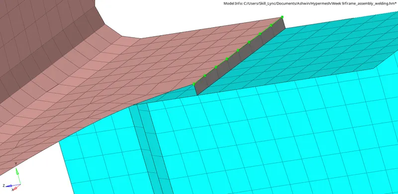
c) Front_truss_2, Front_truss_1 & Right_Rail_1 using Spot weld with 3 Layers and 5 mm Diameter:
i) To mesh the given components, click on 2D -> Automesh -> Select the surface -> Element Size= 6 -> Mesh Type= Mixed -> Check Align and Size boxes under Flow -> Mesh.
ii) The following mesh is obtained:
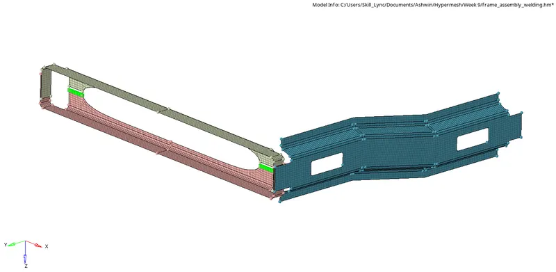
iii)To create a spot element connection, click on 2D -> Connectors -> Spot -> Type = Rigid -> Number of Layers =3 -> Diameter = 5 -> Select the nodes between which connections must be established -> Create.

iv) The realized connector is shown below:
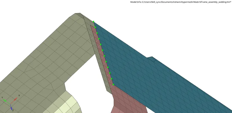
d) Front_truss_2, Front_truss_1 & Left_Rail_1 using Hexa (Adhesive):
i) To mesh the given components, click on 2D -> Automesh -> Select the surface -> Element Size= 6 -> Mesh Type= Mixed -> Check Align and Size boxes under Flow -> Mesh.
ii) The following mesh is obtained:
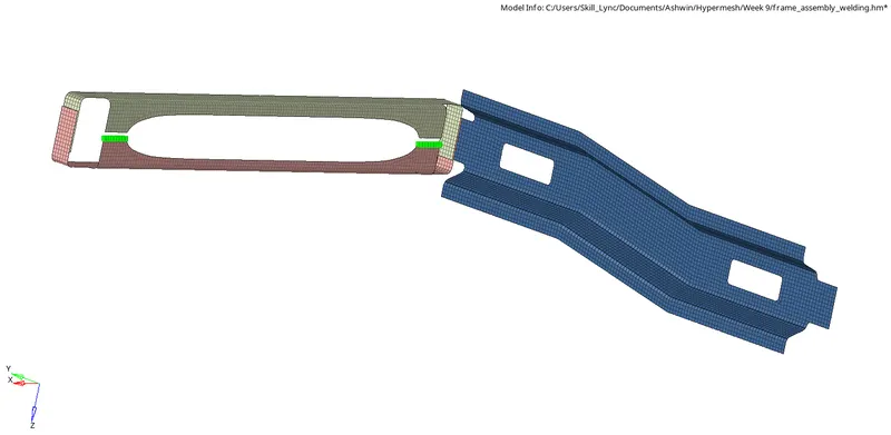
iii) To create an adhesive connection, click on 2D -> Connectors -> Seam -> Create -> Type= Hexa(Adhesive) -> Spacing = Element size =6 -> Select the lines between which connections must be established -> Create.

iv) The realized connector is shown below:
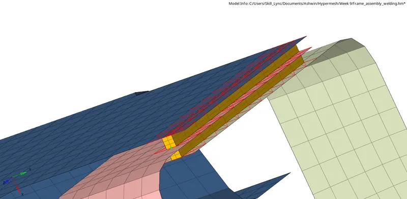
e) Rear_truss_2 & Right_Rail_2 with Bolt Connector:
i) To mesh the given components, click on 2D -> Automesh -> Select the surface -> Element Size= 6 -> Mesh Type= Mixed -> Check Align and Size boxes under Flow -> Mesh.
ii) The following mesh is obtained:
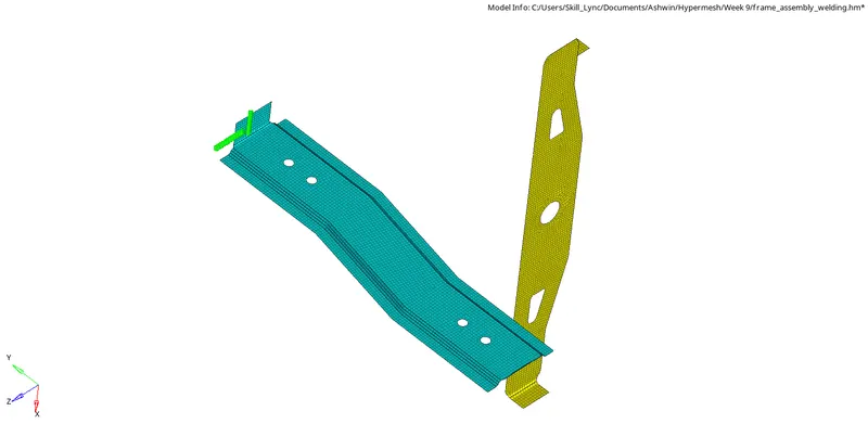
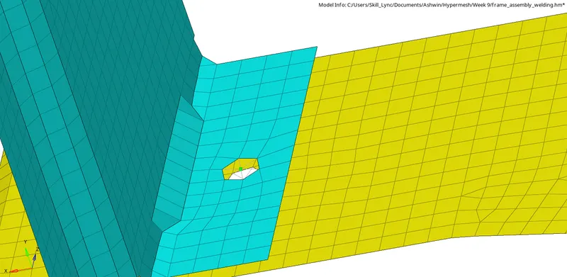
iii) To create a bolt connection, click on 2D -> Connectors -> Bolt -> Type= Bolt(General) -> Select the components between which connections must be established -> Create.

iv) The realized connector is shown below:
f) Rear_truss_2 & Left_Rail_2 using Bolt Connector:
i) To mesh the given components, click on 2D -> Automesh -> Select the surface -> Element Size= 6 -> Mesh Type= Mixed -> Check Align and Size boxes under Flow -> Mesh.
ii) The following mesh is obtained:
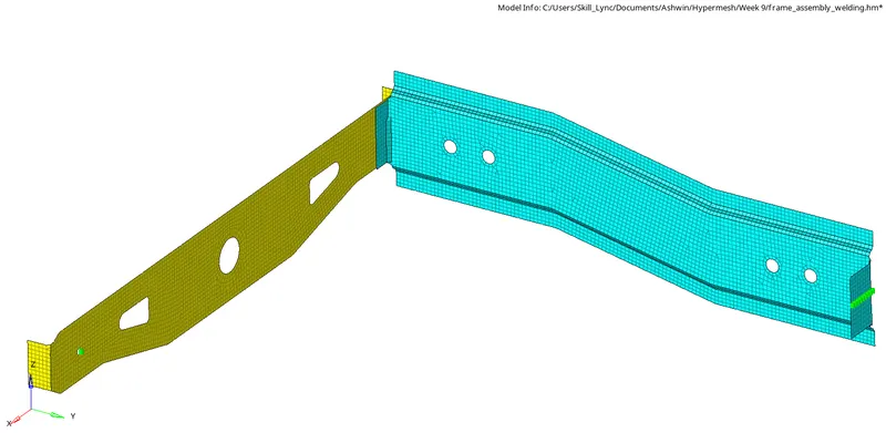
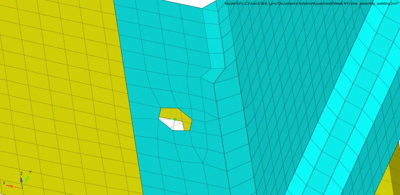
iii) To create a bolt connection, click on 2D -> Connectors -> Bolt -> Type= Bolt(General) -> Select the components between which connections must be established -> Create.
iv) The realized connector is shown below:
g) Right_Rail_1 & Right_Rail_2 using Spot-weld with Rigid Elements:
i) To mesh the given components, click on 2D -> Automesh -> Select the surface -> Element Size= 6 -> Mesh Type= Mixed -> Check Align and Size boxes under Flow -> Mesh.
ii) The following mesh is obtained:
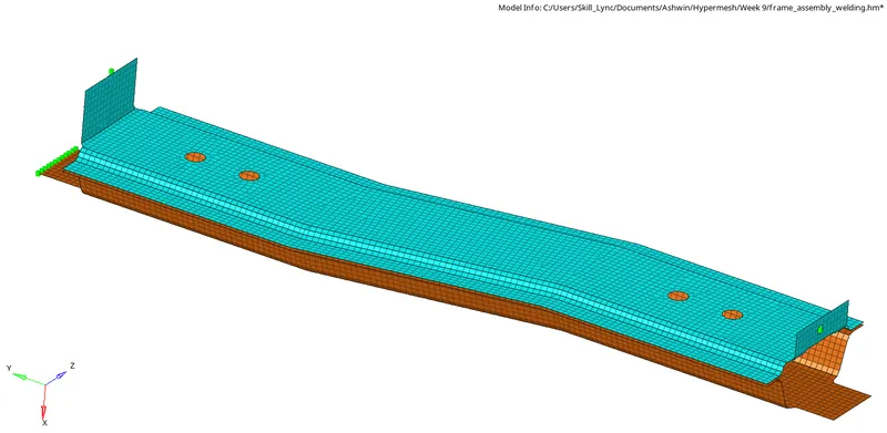
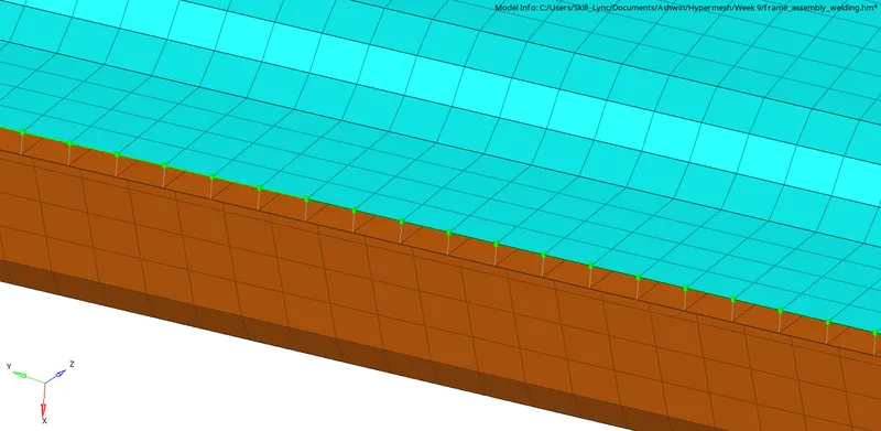
iii) To create a bolt connection, click on 2D -> Connectors -> Seam -> Create -> Type= Rigid -> Spacing = Element size =6 -> Select the lines between which connections must be established -> Create.

iv) The realized connector is shown below:
g) Left_Rail_1 & Left_Rail_2 using Spot-weld with Spring Elements:
i) To mesh the given components, click on 2D -> Automesh -> Select the surface -> Element Size= 6 -> Mesh Type= Mixed -> Check Align and Size boxes under Flow -> Mesh.
ii) The following mesh is obtained:
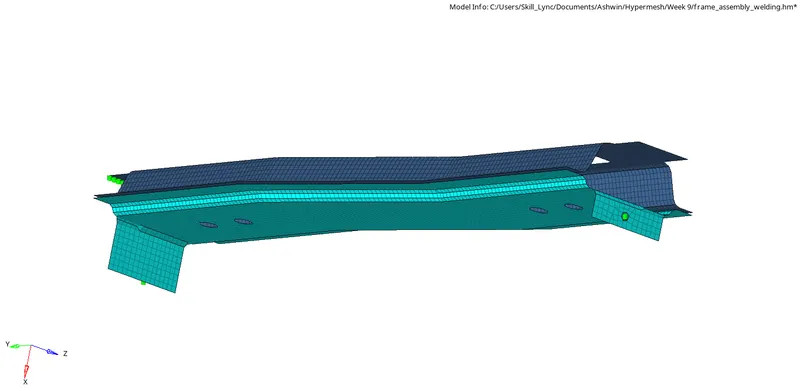
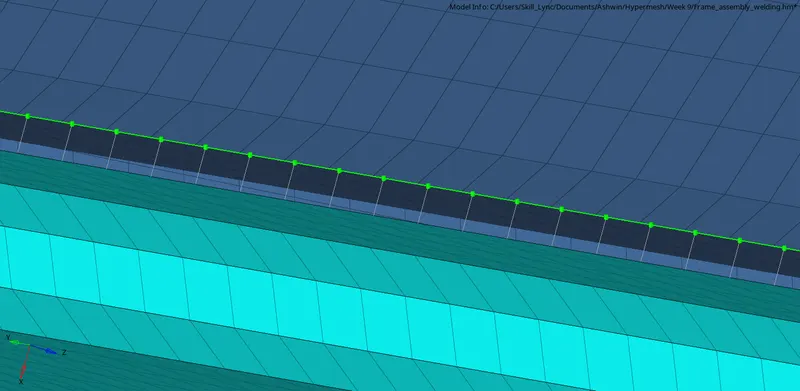
iii)To create a spot element connection, click on 2D -> Connectors -> Spot -> Type = Spring -> Select the nodes between which connections must be established -> Create.

iv) The realized connector is shown below:
i) Mesh the remaining components and establish connection between them using any methods shown above.
RESULT:
All components were meshed and the required connections were made and realized.
CONCLUSION
Studied about the different types of connections and the procedure to realize them.