Assignment 1
OBJECTIVE:
- To extract a midsurface of the given component and perform geometry clean up.
- To mesh the same by following strict quality criteria while obtaining good mesh flow and low tria percentage.
- Assign Property to the models.
PRE-REQUISITES:
- Finite element method(FEM) is a particular numerical method for solving partial differential equations in two or three space variables.
- To solve a problem, the FEM subdivides a large system into smaller, simpler parts that are called finite elements.
- This is achieved by a particular space discretization in the space dimensions, which is implemented by the construction of a mesh of the object.
- By meshing, we can reduce the number of degrees of freedom from infinite to finite.
- Mathematically, the element thickness specified by the user is assigned half on the element top and half on the bottom side.
- Hence, in order to represent the geometry appropriately, it is important to extract the midsurface and mesh on it.
PROCEDURE:
I) Initial Setup:
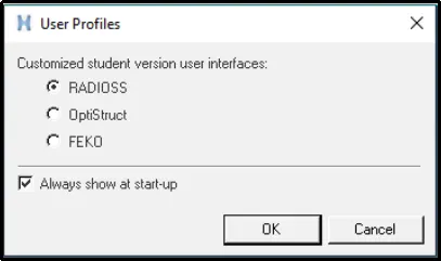
- Select Radioss from the user interface menu.
- Click on Open -> Model -> Select the model.
- The following model is obtained:
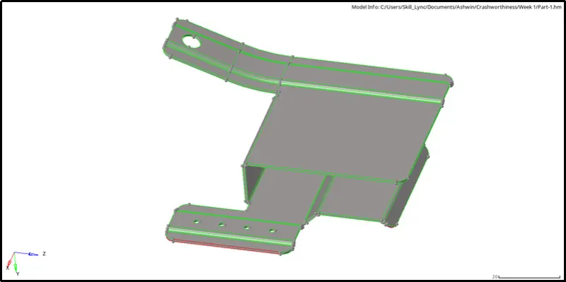
- Change the geometry visualization bar to 'By Topo'.
II) Geometry clean up on the Parent:
- We can observe that the parent component has many defects and deformations.
- If we do not clean it up now, we will not be able to extract a good midsurface and face more problems in the future.
- The following problems we found:
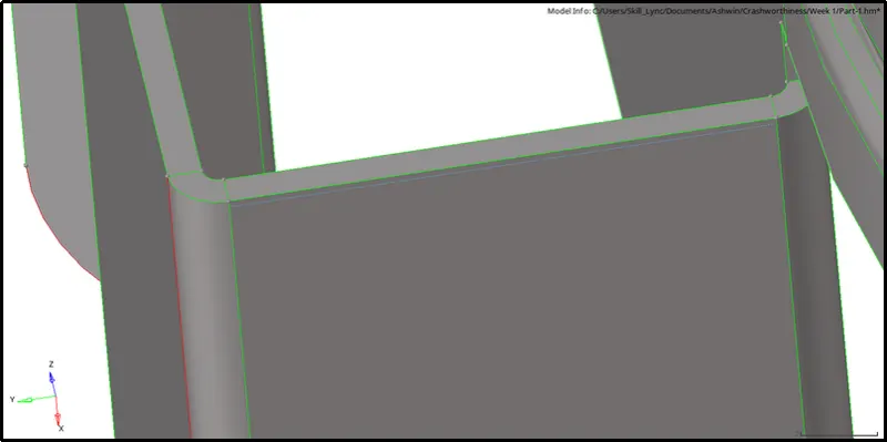
a) Gap in the surface:
i) From the below-shown image, we can see that there is a gap in the surface:
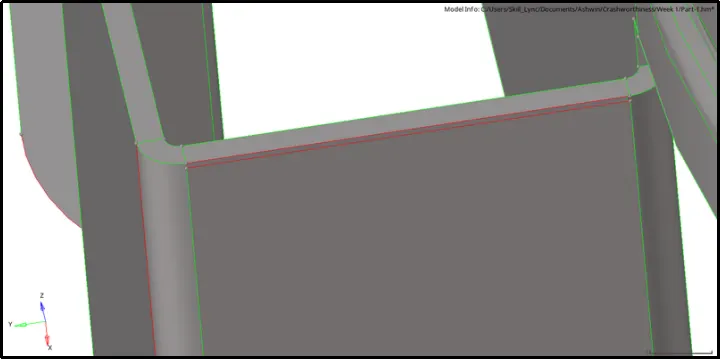
ii) To create a surface, click on Geom -> Quick Edit -> Filler surface.

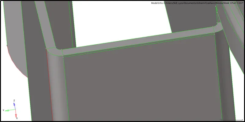
[Note: Shortcut for Quick Edit tool is F11]
iii) Toggle the lines by clicking on Geom -> Quick Edit -> Toggle Edge.
b) Free Edges:
i) From the below-shown image, we can see that there are free edges on the parent surface:
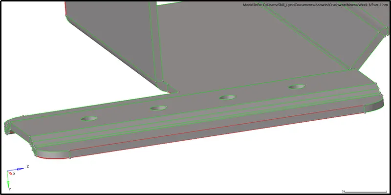
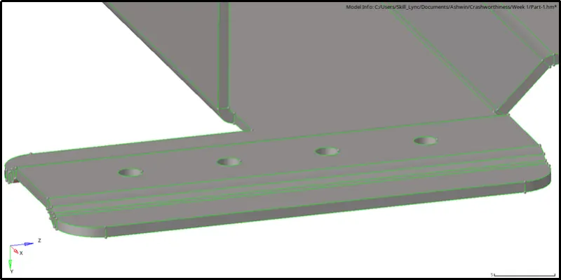
ii) We can get rid of them by clicking on Geom -> Quick Edit -> Toggle Edge.
c) Additional Surface:
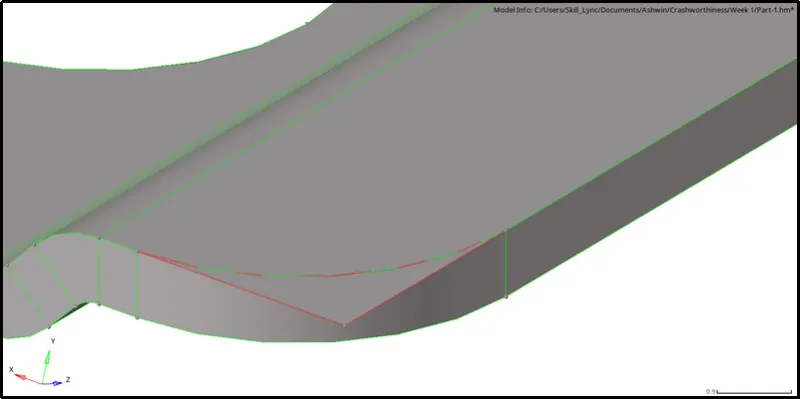
i) From the below-shown image, we can see that a surface is protruding from the geometry:
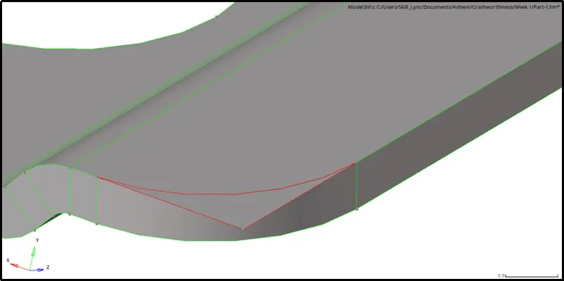
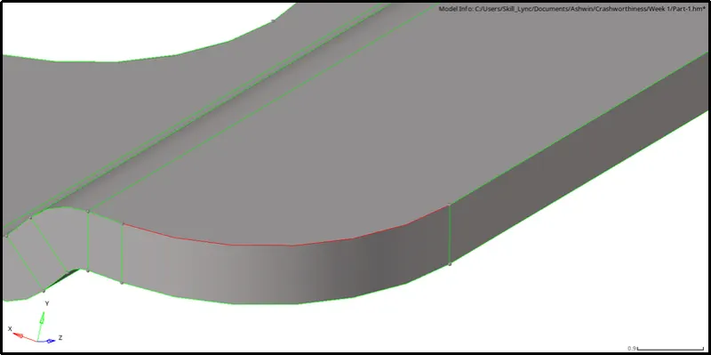
ii) We have to trim the surface by clicking on Geom -> Surface Edit -> Trim with surfaces/Planes -> Select the two surfaces -> Normal to surface -> Trim.
[Note: Shortcut for Surface Edit tool is Shift + F9]
iii) Delete the protruding surface by clicking on Delete -> Surface -> Select the surface -> Delete Entities.
 .
.
 .
.
[Note: Shortcut for Delete tool is F2]
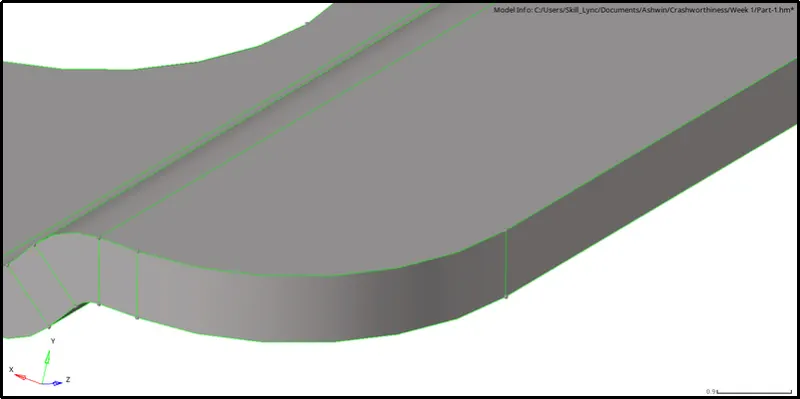
iv) Toggle the free edges by clicking on Geom -> Quick Edit -> Toggle Edge.
d) Duplicate Surfaces:
i) From the below-shown image, we can see triple cons on the surface:
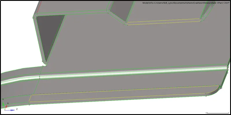
ii) There are many reasons for obtaining a triple con, one such reason is a duplicate surface.
iii)To check for duplicate surfaces, click on Geom -> Defeature -> Duplicates -> Find.

iv) From the below-shown image, we can see that two surfaces were selected indicating that they were duplicates.
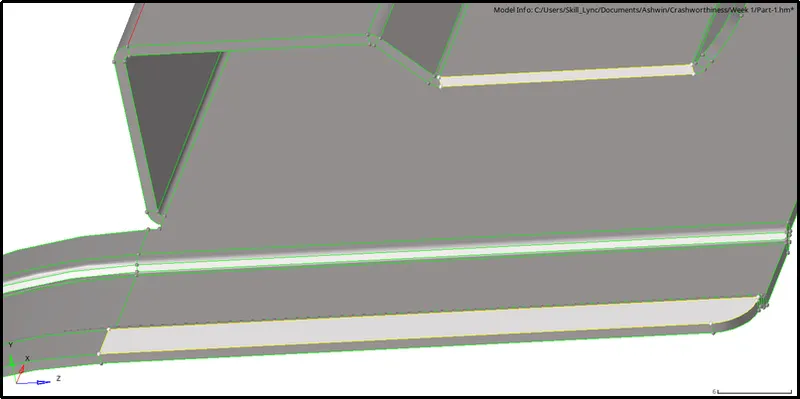
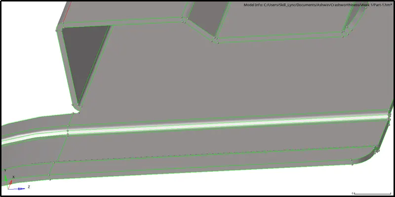
v) To Delete these surfaces, click on Delete -> Surface -> Select the surface -> Delete Entities.
III) Midsurface Extraction:
- Since the component given is a sheet metal component, we can extract the midsurface and mesh the same.
- Midsurface is used to represent the entire 3-D model and create shell elements in it.
- This decreases the processing time and computational power needed to mesh.
[Note: Shell elements are 2-D representation of 3-D elements]
- There are two ways to extract a midsurface:
i) Auto midsurface
ii) Surface offset(Manual method)
- For this particular model, we will use Auto midsurface.
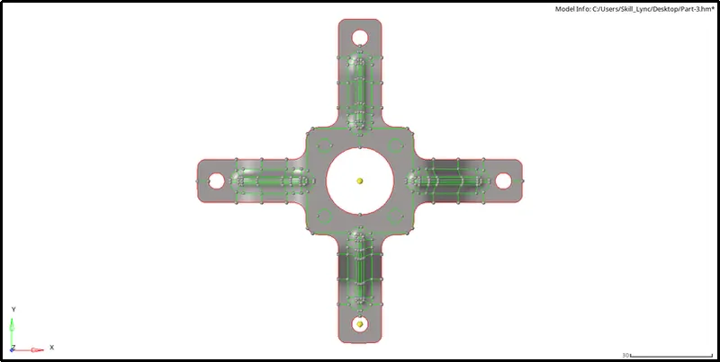
- To extract a midsurface click on Geom -> Midsurface -> Extraction Options -> Skin offset -> Auto Extraction -> Select the surface -> Extract.

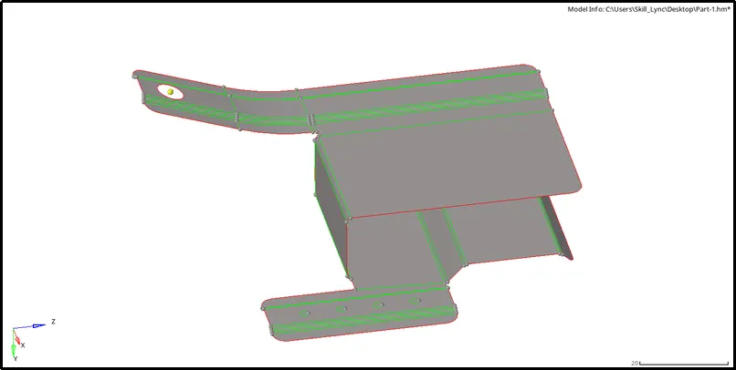
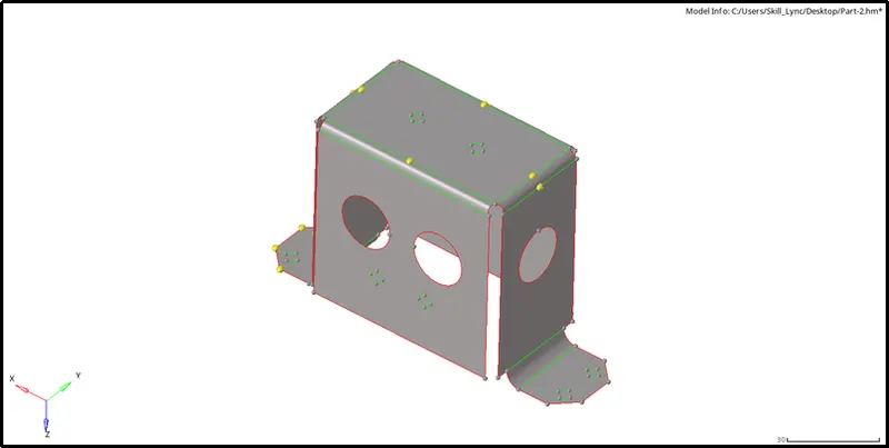
- The following images show the midsurface of their respective components:
 .
.
IV) Geometry Cleanup on the Midsurface:
- We can observe that the midsurface has many defects and deformations.
- The defects found are listed below:
-
a) Regions failing for minimum length:
- i) The following images show the surface that could fail for minimum length criteria:
-
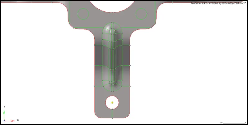
- ii) To deal with this, create a line splitting the surface into two equal halves.
- iii) To do so, click on Geom -> Quick Edit -> Split surface-Line -> Select node and line.
-
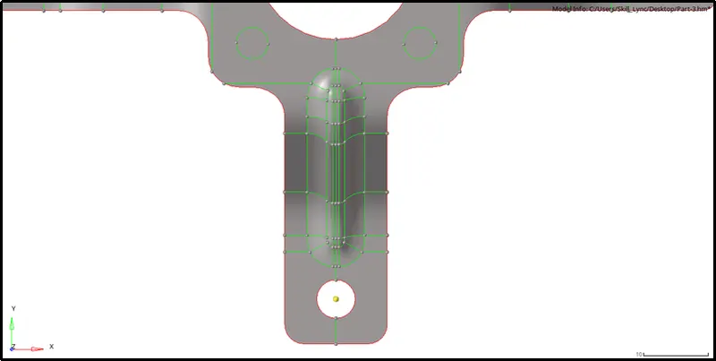
- iv) Toggle all the unnecessary lines.
-

b) Small Holes:
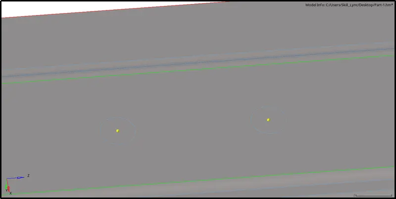
i) Holes having dia less than 5mm can be defeatured.
ii) Before measuring we have to create a central node for the hole.
iii) To create the node, click on Geom -> Nodes -> Arc Center -> Lines -> Select the circumference of the circle -> Create.

iv) To measure the radius of the circle, click on Geom -> Distance -> Two Nodes -> Select two nodes.

v) As shown above, the diameter of the circle is less than 5mm.
vi) We can defeature the hole by filling the surface.
vi) To do so, click on Geom -> Quick Edit -> Filler surface.
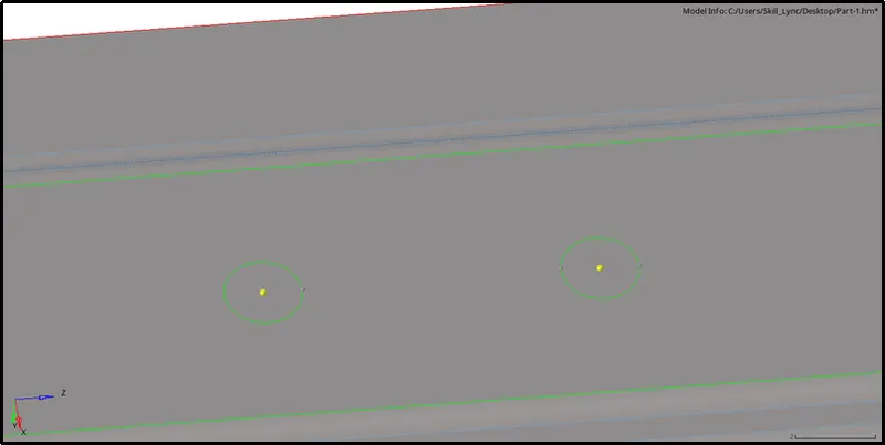
vii) Toggle all the unnecessary lines.
V) Meshing:
- Before meshing we have to keep the following things in mind:
a)Always start meshing the complex component first.
b) Start meshing from the surface with the most features or the surface with free edges.
- To mesh a given surface click on 2-D -> Automesh -> Surface -> Select Surface -> Element size= 4 -> Mesh type= Mixed -> Check Align and Size box under Flow -> Mesh.

[Note: The shortcut for Automesh tool is F12]
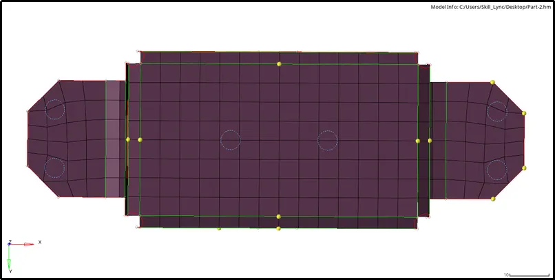
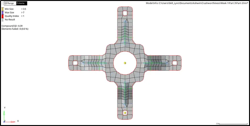
- The component shown below is symmetric in nature:
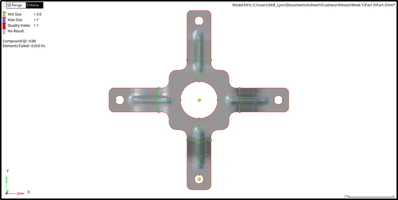
- Therefore, in order to save time, we can mesh one quarter and reflect the elements to the rest of the surfaces.
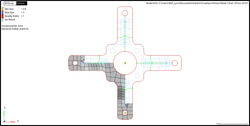
- To reflect, click on Tools -> Reflect -> Select the elements -> Duplicate -> Select the respective axis -> select the Base node -> Reflect.

- The final mesh is displayed below:
V) Quality:
- Following quality criteria is of utmost importance in any Industry.
- Different quality criterias followed in Hypermesh are listed below:
|
S.N |
Quality Criteria |
Definition |
|
1 |
Aspect Ratio |
The ratio of Maximum length to Minimum length |
|
2 |
Skewness |
The angular measure of element quality with respect to the angles of ideal element types |
|
3 |
Warping |
The angle between two planes on the same element |
|
4 |
Taper |
Angular distortion of a quadrilateral shell element |
|
5 |
Min. Length |
Edge of the element with the least length |
|
6 |
Max. Length |
Edge of the element with the highest length |
|
7 |
Min angle Quad |
The lowest angle between any two edges in a quad element |
|
8 |
Max angle Quad |
The highest angle between any two edges in a quad element |
|
9 |
Min angle Tria |
The lowest angle between any two edges in a Tria element |
|
10 |
Max angle Tria |
The highest angle between any two edges in a Tria element |
|
10 |
Tria % |
Number of trias present with respect to Number of quads |
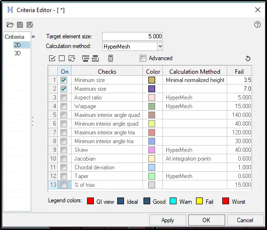
- However, for the models given to us we only need to follow the following criterias:
| SL NO. | Quality Criteria | Value |
| 1. | Element Target Length | 5 |
| 2. | Minimum Size | 3.5 |
| 3. | Maximum Size | 7 |
- To save the above criteria click on Preferences -> Criteria File Setting -> Enter the parameters -> OK
- The following rules must be followed when it comes to tria management:
-
i) No trias should be formed on corners or edges(especially free edges).
ii) No opposite trias should be formed.
iii) Back to back must not be there.
iv) Rotational quads must not be formed.
v) Trias should not share a boundary with the feature line.
vi) Elements must be properly connected.
- After meshing we can notice that a few elements have not passed the quality criteria.
- The failed criteria and methods used to clear them are discussed below:
a) Maximum size and Minimum Size:
i) The following image shows elements failing for Maximum and Minimum size:
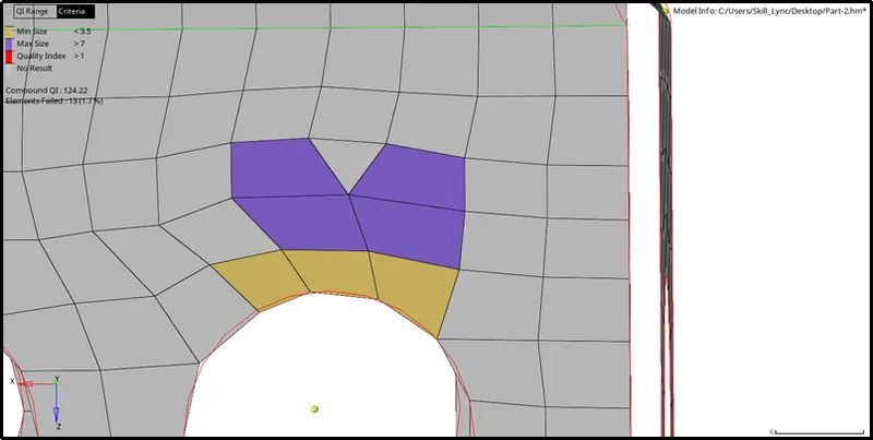
ii) We can fix this by using smooth.
iii) To do so click on 2-D -> Quality Index -> Cleanup tools -> Select the failing element and the surrounding elements within the feature -> Smooth.

iv) After using smooth, the element has passed all criteria.
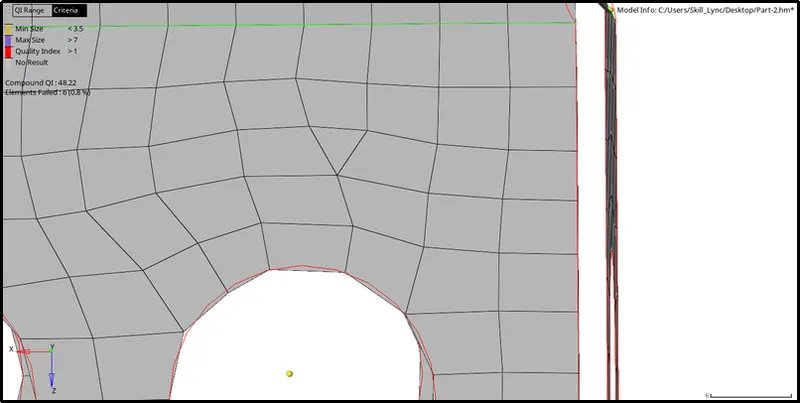
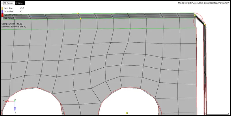
a) Opposite Trias:
i) The following image shows two opposite trias on the same surface:
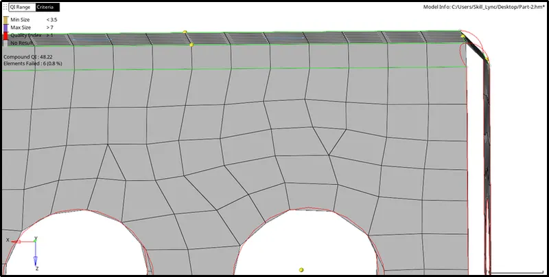
ii) We can get rid of them by dragging them into each other creating a quad element.
iii) To do so, click on 2-D -> Quality Index -> Cleanup tools -> Drag the trias into each other.
VI) Equivalence:
- After meshing we need to check for free edges in the mesh.
- To do so, click on Tool -> Edges -> Elements -> All -> Tolerance= 0.5 -> Find free edges.

[Note: Shortcut for Edges tool is Shift +F3]
- From the below image we can see that there are many free edges in the model:
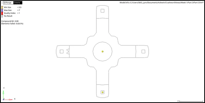
- To clear them, click on Tool -> Edges -> Elements -> All -> Tolerance= 0.5 -> Preview Equivalence -> Equivalence.
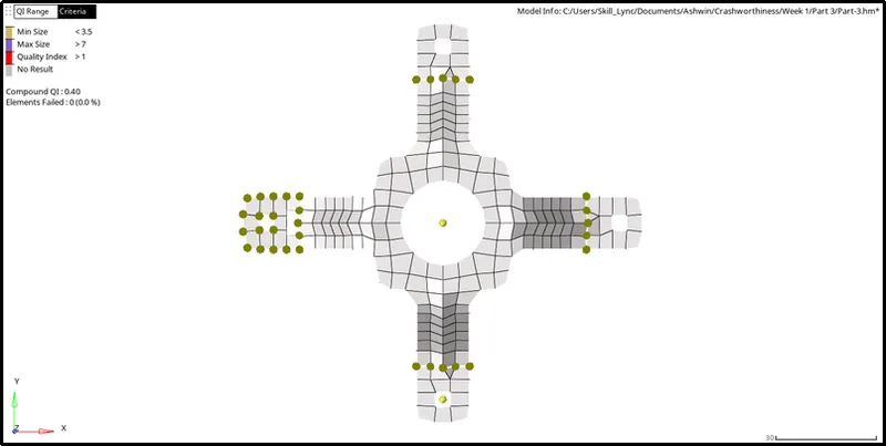
- Repeat the process to find the free edges again with different tolerances.
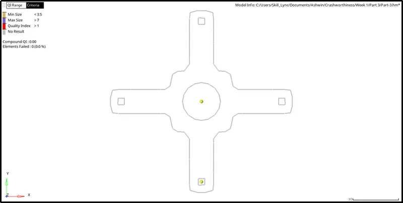
- The below image shows the absence of any free edges within the model:
VII) Assigning Thickness(Property):
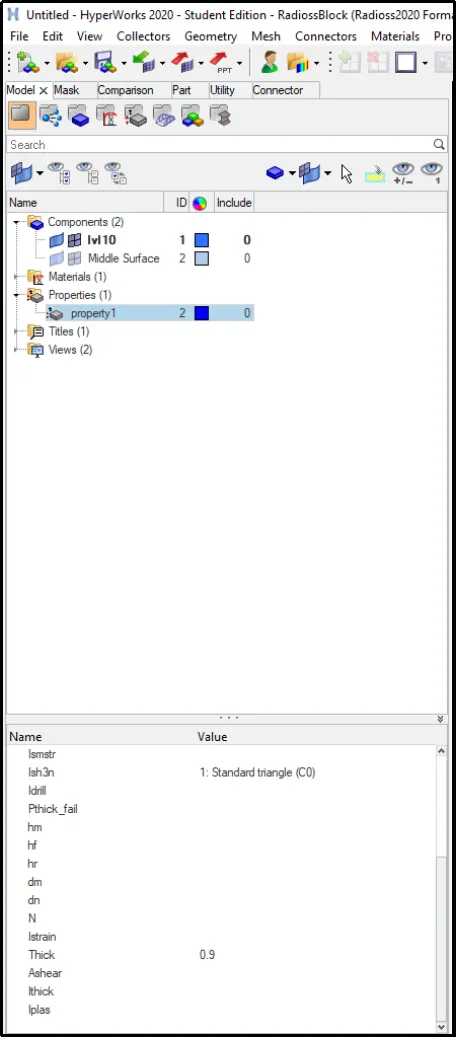
- To assign thickness, first, we need to create a property.
- To do so, Right- Click on the Model bar -> Create -> Property.
- In the Card edit menu, assign thickness=0.9.
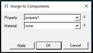
- After creating the property assign it to the midsurface by Right-Clicking on Midsurface component -> Assign -> Select the created property -> OK.
- Assign thickness to all the models using the aforementioned procedure.
RESULTS:
- Performed geometry cleanup on the parent to get rid of deformations.
- Extracted the midsurface manually and performed cleanup on it as well.
- Obtained a good mesh flow and cleared all elements for quality.
- Assigned thickness to the model.
- The following table shows all the models passing all quality criterias:
| Part | Model |
| 1. | 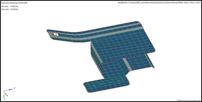 |
| 2. | 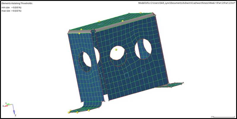 |
| 3. | 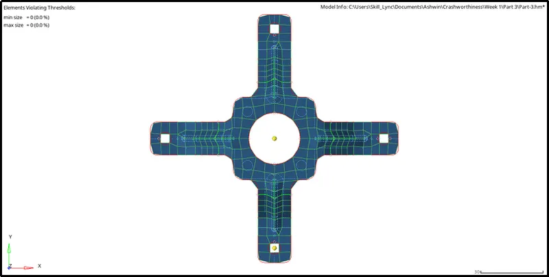 |
CONCLUSION:
- Understood the difference between auto-midsurface and manual midsurface and the reasoning behind choosing Auto midsurface method for this particular model.
- Learnt different methods to recreate the surface in case of deformation.
- Learnt different tools required to clear all quality criterias.