Assignment 3
QUESTIONS:
- Using the crash beam file to get the model and change the run time to 55 ms.
- Change the number of animation steps during simulation to a minimum of 25 and a maximum of 60.
- Run the base simulation without any modification to element properties.
- At the end of the simulation, do the energy error and mass error checks and determine whether the results would be acceptable.
- If acceptable, Plot rigid wall forces, internal energy, hourglass energy, contact energy and the total energy of the simulations.
- Now, change all the shell elements properties to the recommended properties, save this as separate, .rad files and run the simulation.
- At the end of the simulation, do the energy error and mass error checks and determine whether the results would be acceptable.
- If acceptable, Plot rigid wall forces, internal energy, hourglass energy, contact energy and the total energy of the simulations.
- Create a brief report comparing all the results from the graphs for both simulations.
- Comment whether there is any change in the results and why there is any change in the result.
- Give a detailed explanation of hourglass energy, its causes and the steps to avoid it.
| S.L NO | Parameters | Comment |
|
1. |
Ishell =24 |
QEPH 4 node shells are the best combination of cost and accuracy. |
|
2. |
Ismstr=2 |
Full geometric nonlinearities (default)with possible small strain formulation activation in RADIOSS Engine. |
|
3. |
Ish3n=2 |
Standard 3 noded shell (C0)with modification for large rotation(default) |
| 4. | N=5 | Number of integration points set to 5 for accuracy bending. |
|
5. |
Ithick=1 |
Thickness change is taken into account for accuracy. |
|
6. |
Iplas=1 |
Iterative plasticity for good accuracy. |
PRE-REQUISITES:
- Different types of quad elements are listed below:
| SL NO. | Element | `I underset (shell)` | Integration | Cost |
| 1. | Q4 | 1,2,3,4 | Reduced | 1.0 |
| 2. | QBAT | 12 | Full | 2.0 |
| 3. | QEPH | 24 | Reduced | 1.15 |
- From the above-shown table, we can conclude that the QEPH element has the best combination of cost and accuracy.
- The reduced Gaussian Integration points mean that the calculation is done on only one Gaussian point.
- This yields faster results but the accuracy might not be good.
- Since QEPH and Q4 are under-integrated elements, Hourglass might be formed in them.
- Hourglass is a condition where the element gets deformed but the stresses are not getting recorded.
- It is a non-physical zero-energy mode.
- It leads to inaccurate strain and displacement results.
- There are two methods used to control Hourglassing:
a) Perturbation Method:
i) This method is used only for Q4 elements.
ii) If hourglass is detected, an opposing force is applied on the node to stabilize the deformation (damping).
iii) Magnitude of the force applied depends on the material properties.
iv) The opposing forces produce an artificial energy called hourglass energy.
v) This additional (artificial) energy added when subtracted with the total system energy is called energy error.
vi) The overall energy error should be negative and between -15% to 5%.
vii) If the energy error increases and then decreases then the results are acceptable.
viii) But if it increases continuously it means that there is an issue with the model.
ix) The closer the value is to zero the better.
x) One disadvantage is that Q4 elements fail in the case of large rotation and elastic loading-unloading cycles.
b) Physical Stabilization Method:
i) This method is used only for QEPH elements.
ii) Shell elements control the hourglass from the material level.
iii) Hourglass loading stiffness and hourglass yield depends on the model's material properties like natural tangent modulus and natural yield respectively.
iv) While considering the calculation of stresses on nodes if the stress on one node is not calculated(due to hourglass) we can use this method.
v) In order to avoid hourglass we have to provide stiffness to that node i.e, add mass to that node.
vi) This additional(artificial) mass added when subtracted with the total mass in the system is called mass error.
vii) The mass error should not be more than 2% of the total mass.
viii) The advantage of this method is that it works well with all kinds of loading and unloading cases.
INITIAL SETUP:
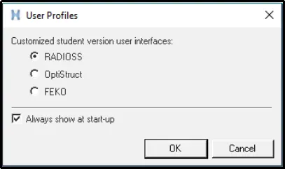
- Select Radioss from the user interface menu.
-
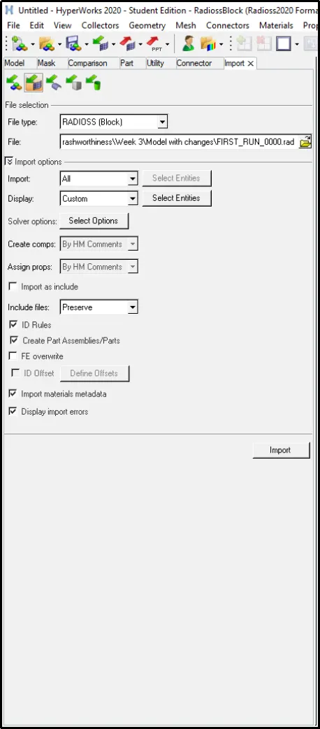
First, we need to import the model into Hypermesh.
-
To do so, click on Import -> Import Solver Deck -> Choose the starter file -> Import.
-
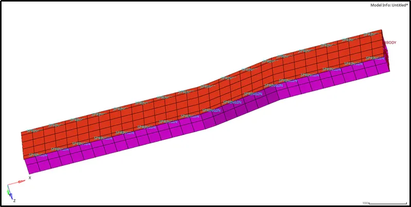
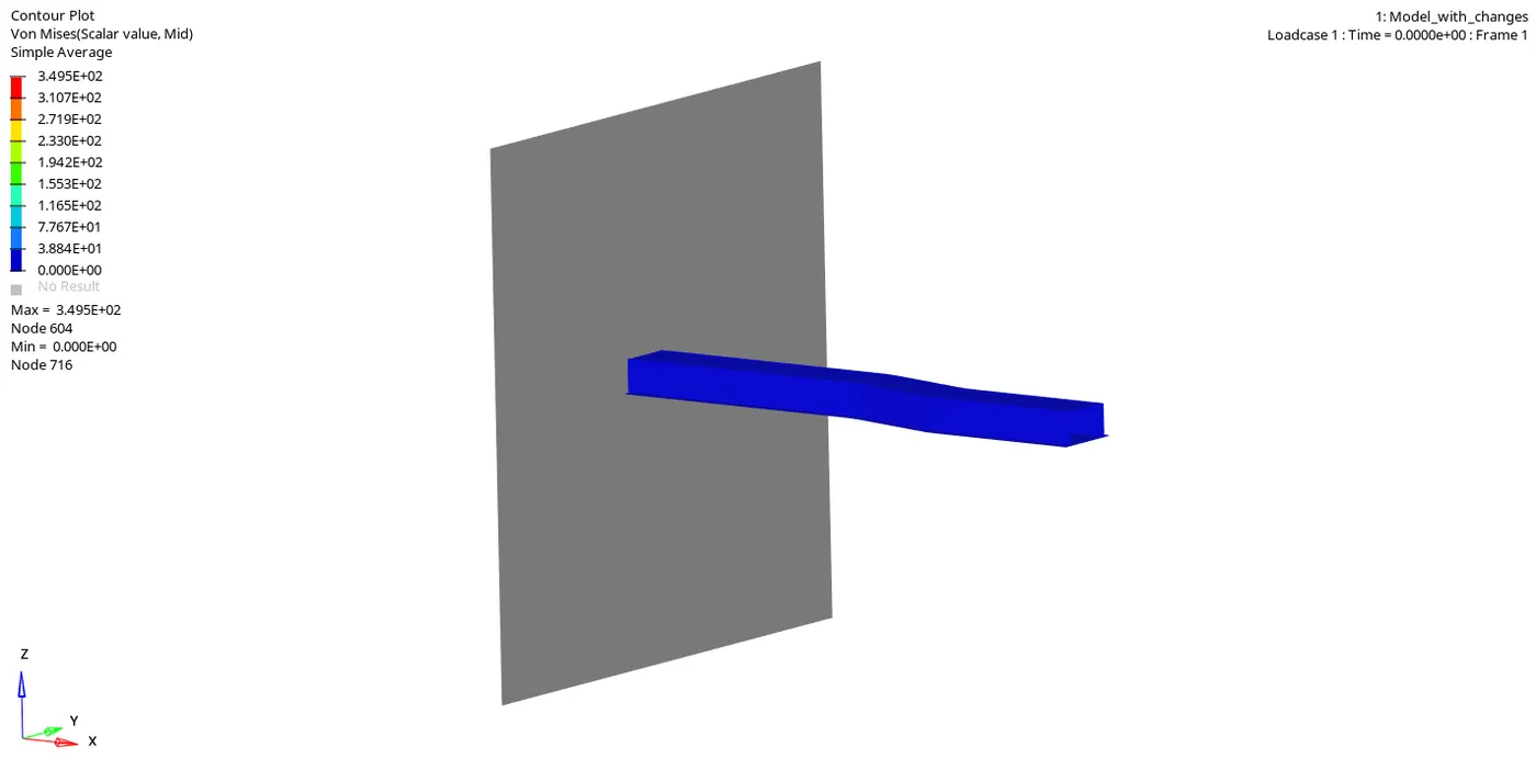
The following model is obtained:
ANSWERS:
1) Using the crash beam file to get the model and change the run time to 55 ms
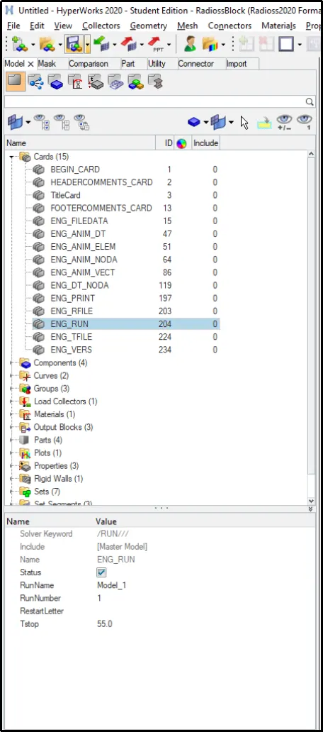
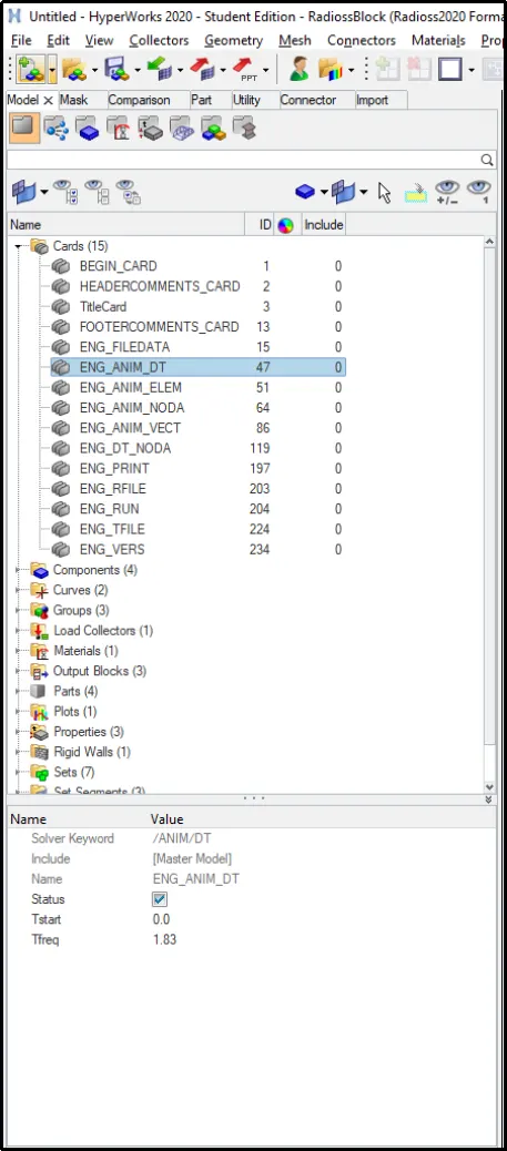
i) To set the run time value, click on the ENG_RUN card -> Set the value of Tstop= 55.
2) Change the number of animation steps during simulation to a minimum of 25 and a maximum of 60
i) To get the animation steps within a certain number, we need to alter the Tf value in the model.
ii) We know that,
`T undersetf`= `(Run Time)/(Number of Animation Steps)`
= `55/30`
= 1.83 Hz
3) Run the base simulation without any modification to element properties
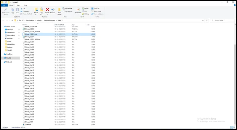
i) Without changing any shell properties, click on Analysis -> Radioss -> Select the starter file -> Radioss.

ii) After the simulation is completed, we can see that 30 animation files have been created in the root folder.
4) At the end of the simulation, do the energy error and mass error checks and determine whether the results would be acceptable
i) To check the energy error and the mass error of the simulation open the .out engine file in Notepad.
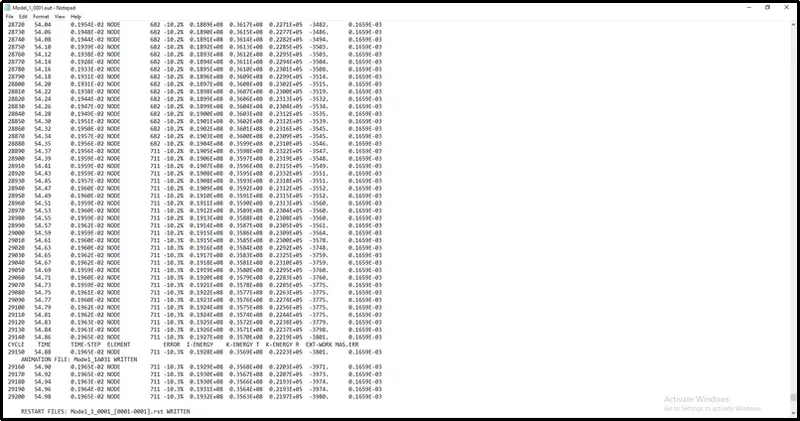
ii) From the above image, we can see that the Energy error ranges from 0% to -10.3% and mass added is constant at 0.1659E-03 which is well within the acceptable range.
5) Plot rigid wall forces, internal energy, hourglass energy, contact energy and the total energy of the simulations
i) To plot the graphs we first have to close Hypermesh and open HyperView and HyperGraph in two windows.
ii) Load the .h3d file in HyperView and the T01 file in HyperGraph.
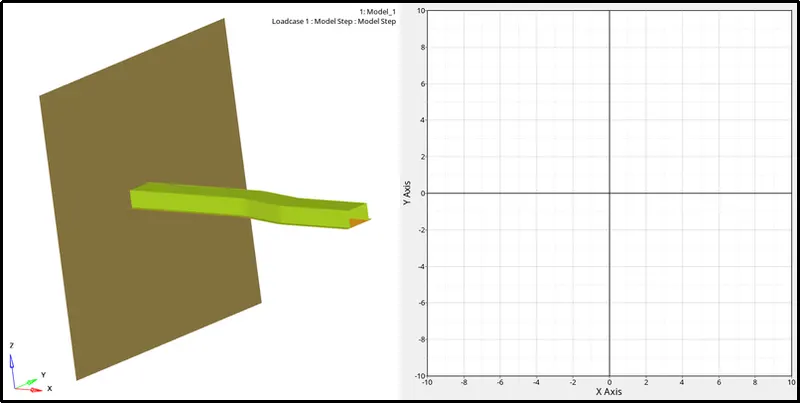
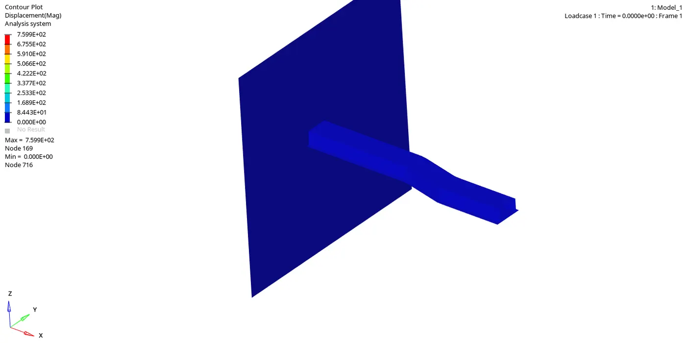
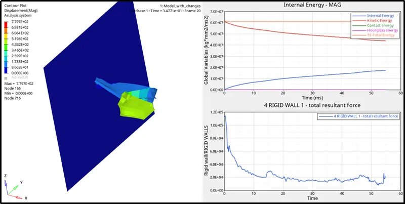
iii) To see the animation and deformation in the material with respect to displacement, click on HyperView window -> Select the .h3d file -> Contour -> Result type(v) -> Displacement -> Apply.

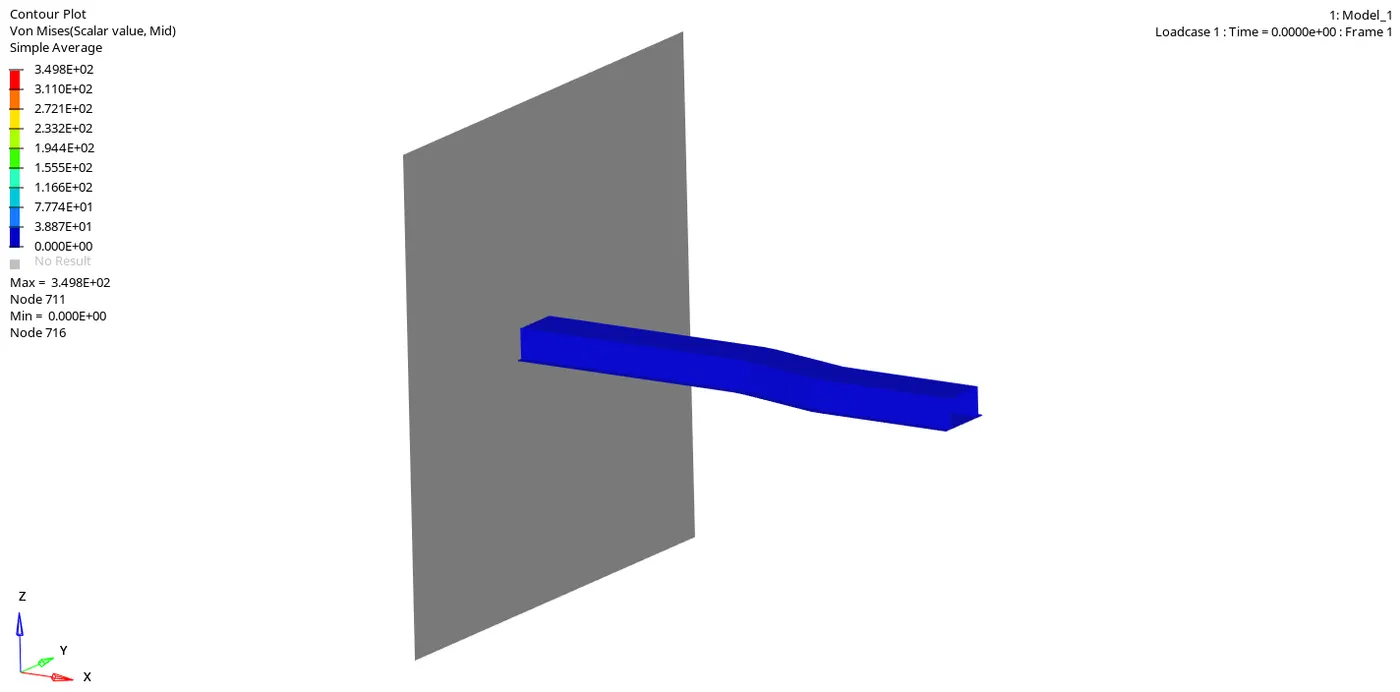
iii) To see the animation and deformation in the material with respect to Von Mises stress, click on HyperView window -> Select the .h3d file -> Contour -> Result type(v) -> Von Mises-> -> Averaging method=Simple -> Apply.

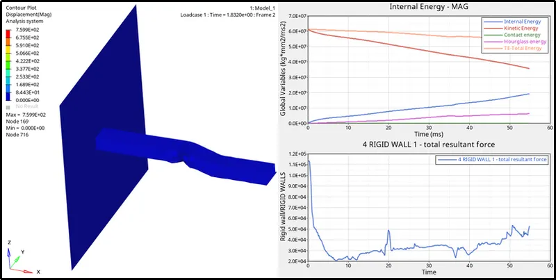
iv) To plot the graphs, click on HyperGraph window -> Select the T01 file -> Y Type -> RIGID WALLS -> X type= Time -> Apply.
v) To plot the rest of the graphs go to, HyperGraph window -> Select the T01 file -> Y Type ->Global Variables ->Select Internal Energy, Hourglass energy, Contact Energy and Total Energy together -> MAG -> X type= Time -> Apply.

6) Change all the shell elements properties to the recommended properties and run the simulation
i) To set the run time value, click on the ENG_RUN card -> Set the value of Tstop= 55.
ii) To get the animation steps within a certain number, we need to alter the Tf value in the model.
iii) We know that,
`T undersetf`= `(Run Time)/(Number of Animation Steps)`
= `55/30`
= 1.83 Hz
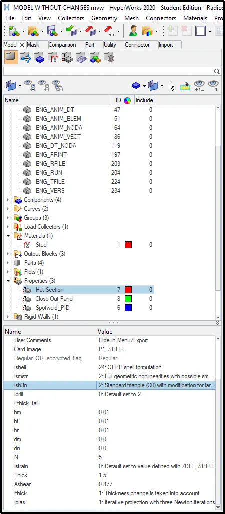
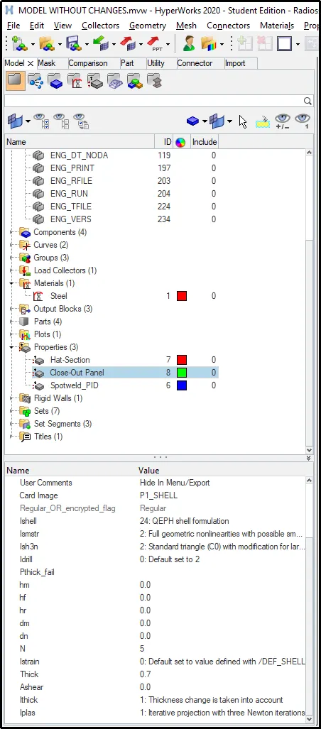
iv) To change the properties, click on the Property folder -> Select Hat-Section and Close-out panel -> Go to the Propert card image bar and change the parameters to the recommended properties.
v) Without changing any shell properties, click on Analysis -> Radioss -> Select the starter file -> Radioss.
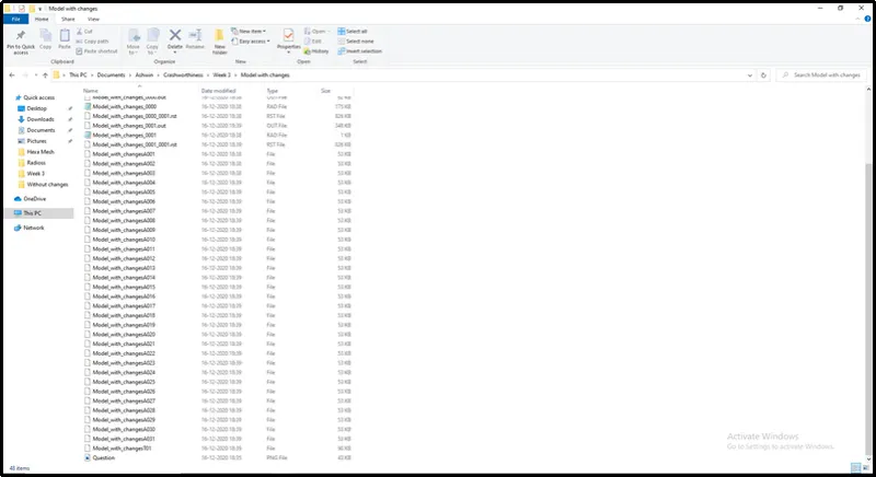
vi) After the simulation is completed, we can see that 30 animation files have been created in the root folder.
7) At the end of the simulation, do the energy error and mass error checks and determine whether the results would be acceptable
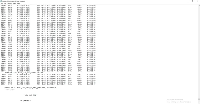
i) To check the energy error and the mass error of the simulation open the .out engine file in Notepad.
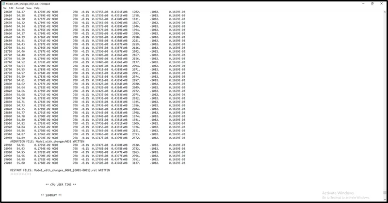
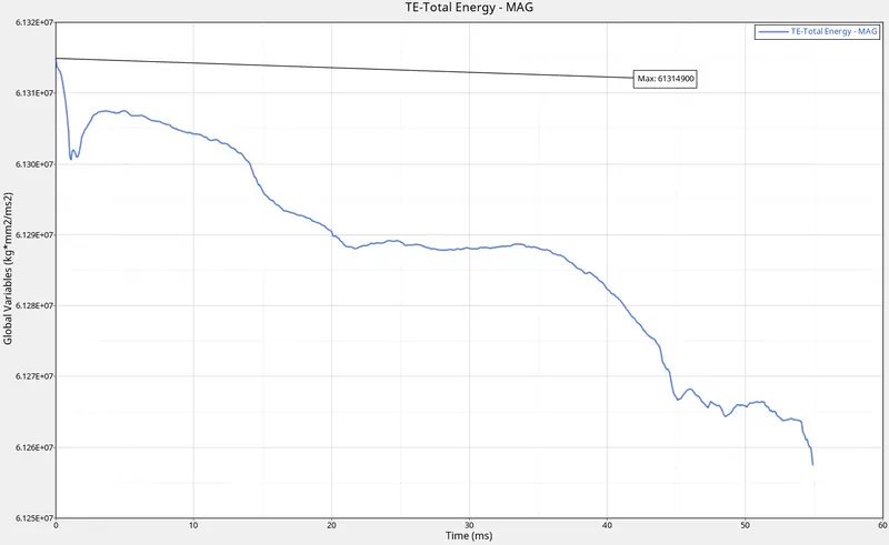
ii) From the above image, we can see that the Energy error ranges from 0% to -0.1% and mass added is constant at 0.1659E-03 which is well within the acceptable range.
8) Plot rigid wall forces, internal energy, hourglass energy, contact energy and the total energy of the simulations
i)To plot the graphs we first have to close Hypermesh and open HyperView and HyperGraph in two windows.
ii) Load the .h3d file in HyperView and the T01 file in HyperGraph.
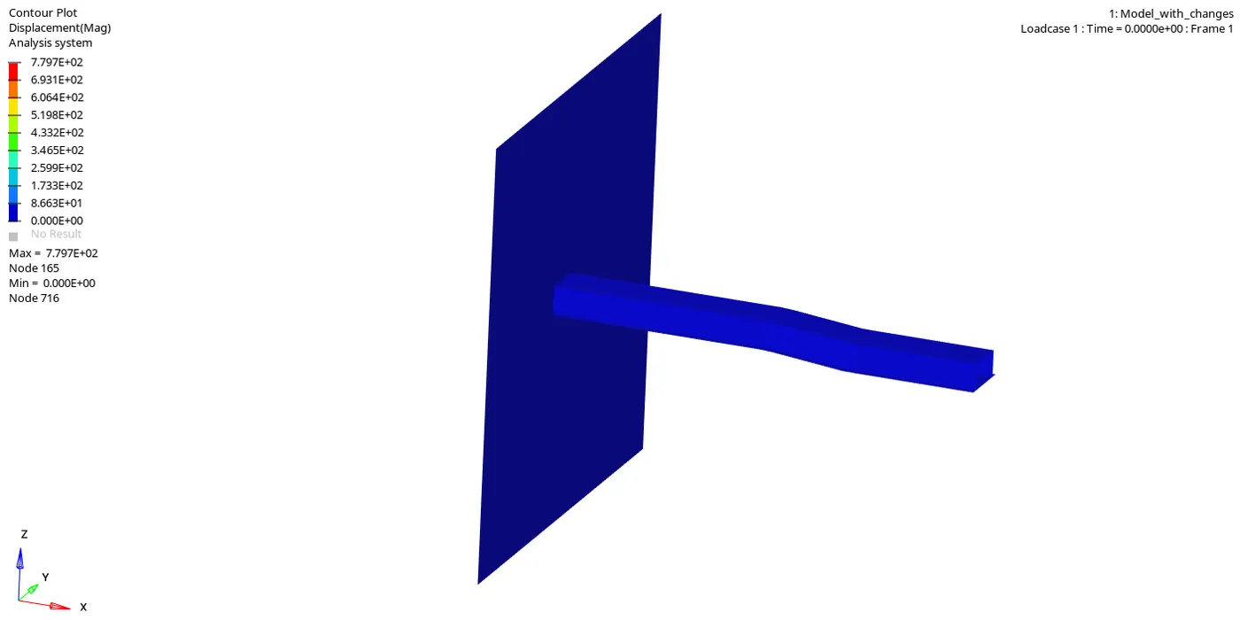
iii) To see the animation and deformation in the material with respect to displacement, click on HyperView window -> Select the .h3d file -> Contour -> Result type(v) -> Displacement -> Apply.
iii) To see the animation and deformation in the material with respect to Von Mises stress, click on HyperView window -> Select the .h3d file -> Contour -> Result type(v) -> Von Mises-> -> Averaging method=Simple -> Apply.
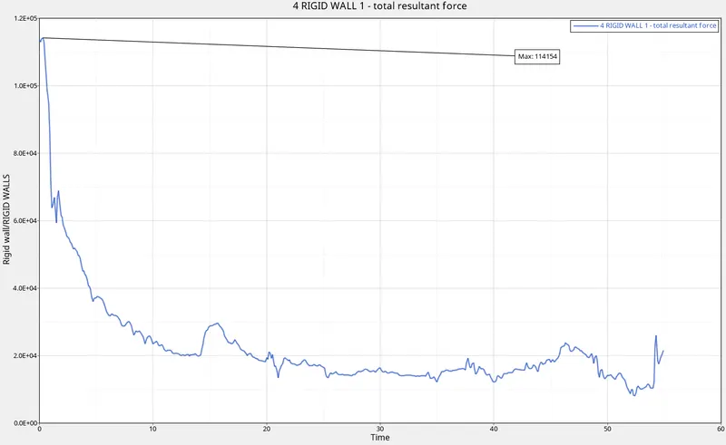
iv) To plot the Rigid wall graph, click on HyperGraph window -> Select the T01 file -> Y Type -> RIGID WALLS -> X type= Time -> Apply.
v) To plot the rest of the graphs go to, HyperGraph window -> Select the T01 file -> Y Type ->Global Variables ->Select Internal Energy Hourglass energy, Contact Energy and Total Energy together -> MAG -> X type= Time -> Apply.
RESULTS:
a) Plots:
| SL NO. | Parameter | Simulation 1(without changes) | Simulation 2(with changes) |
| 1. | Internal Energy | 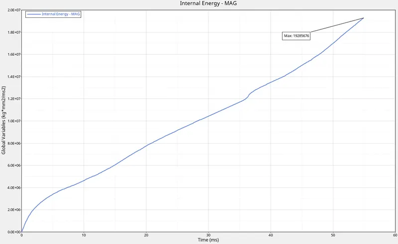 |
 |
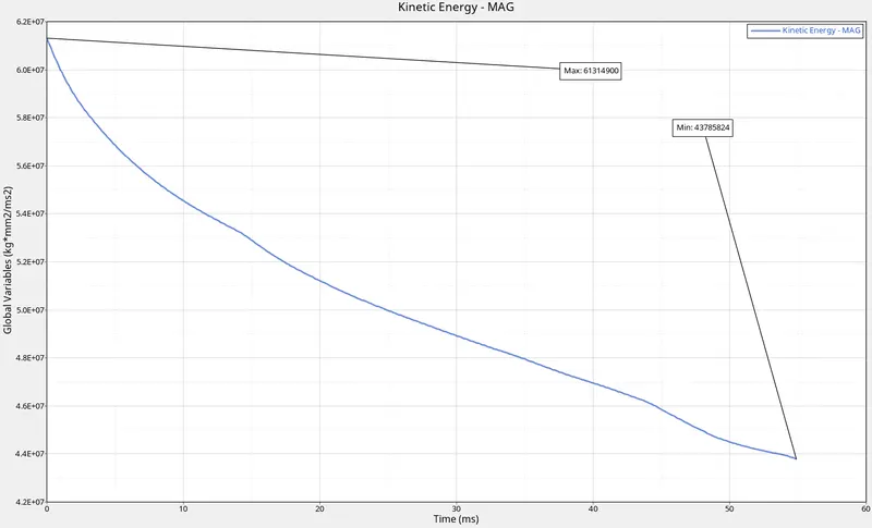
| 2. | Kinetic Energy | 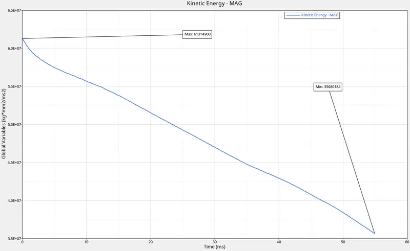 |
 |
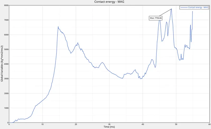
| 3. | Contact Energy | 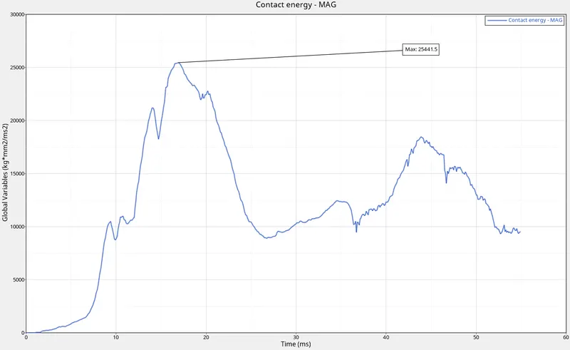 |
 |
| 4. | Hourglass Energy | 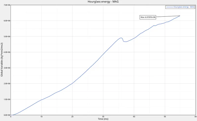 |
 |
| 5. | Internal Energy vs Kinetic Energy | 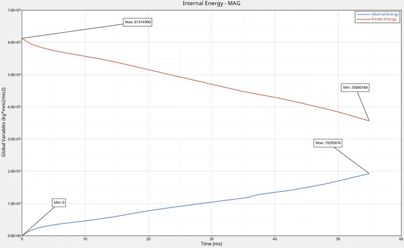 |
 |
| 5. | Total Energy | 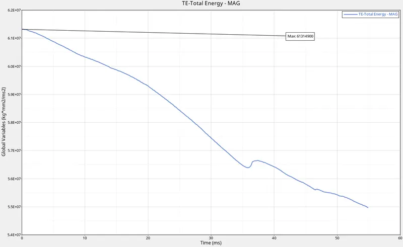 |
 |
| 6. | All | 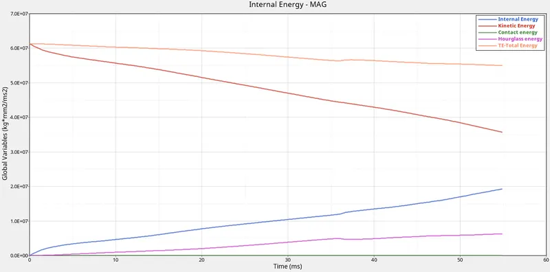 |
 |
| 7. | Energy and mass error | 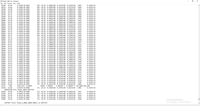 |
 |
| 8. | Rigid Wall forces | 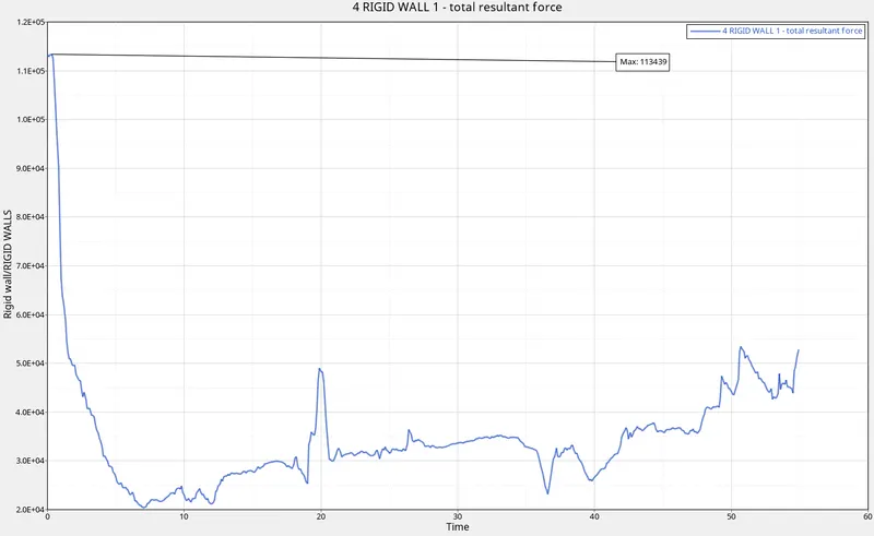 |
 |
b) Observations:
| S.L No | Name | Value for Case 1 | Value for Case 2 |
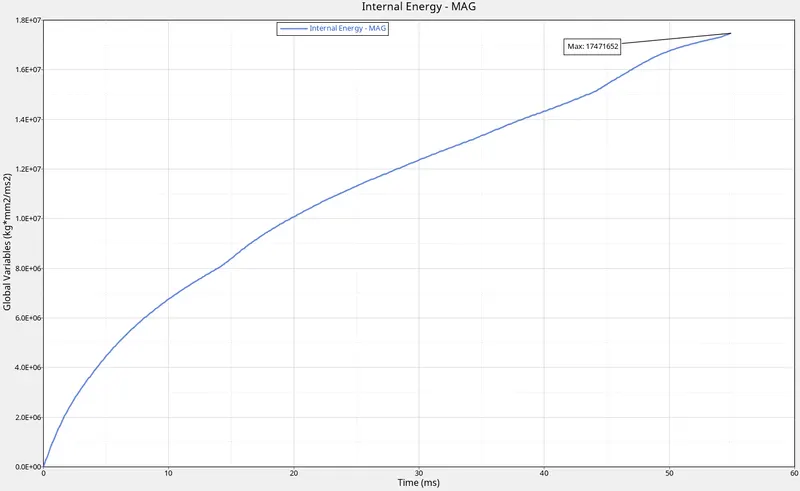
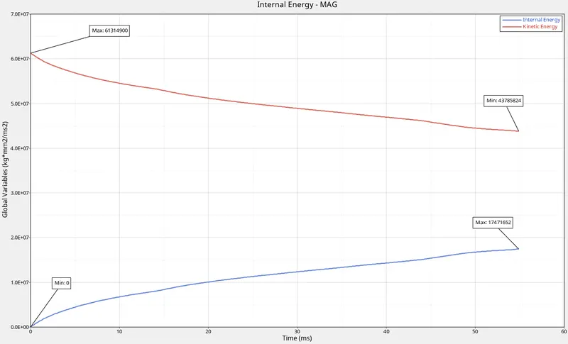
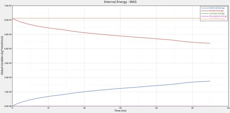
| 1. | Internal Energy | 1.93E+07 | 1.75E+07 |
| 2. | Kinetic Energy | 6.13E+07 | 6.13E+07 |
| 3. | Contact Energy | 2.54E+03 | 7.75E+03 |
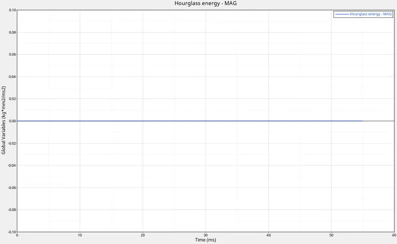
| 4. | Hourglass Energy | 6.31E+06 | 0 |
| 5. | Total Energy | 6.13E+07 | 6.13E+07 |
| 6. | Rigid Wall Forces | 1.13E+05 | 1.14E+05 |
| 7. | Energy Error | -10.3% | -0.1% |
| 8. | Mass error | 0.1659E-03 | 0.1659E-03 |
i)The high kinetic energy in the beginning is due to the motion of the beam itself.
ii) This slowly decreases due to the impact on the rigid wall.
iii) This kinetic energy is now getting converted to strain energy due to the deformation of the beam.
iv) Here, strain energy is nothing but Internal Energy.
v) Therefore we can conclude that the kinetic energy of the car is getting converted to internal energy.
vi) Internal energy is lesser than Kinetic Energy due to energy error.
vii) Hourglass energy is 0 in the second case due to the selection of QEPH element.
viii) Energy error is reduced from -10.3% to -0.1% by using the recommended properties.
CONCLUSION:
i) With default shell properties the deformation does not look natural.
ii) To overcome this we use the recommended properties.
iii) QEPH Ishell=24 with inbuilt hourglass stabilization was used to analyze deformations and transfer stresses more effectively.