Assignment 2-RADIOSS Engine File Editing & 3D Meshing Challenge
AIM -
- Check the material properties of the rail component and calculate the speed of sound in steel rail=_______
- The length of the rail is about 1000 mm.calculate the time takes for a shock wave to travel from one end of the rail to the other.
3.Time for sound to travel length of rail=______
4.Edit the engine file so that the stress wave can be monitored, moving from one end of the rail to the other during impact -this will require a termination time equal to the time it takes for the sound to travel the length of the rail(set on/RUN card)
5.Set the frequency of animation output to a time that will give 20 animation steps(/ANIM/DT)
6.Change /print -10.
7.3d meshing tetra mesh and hex mesh
- Repeat class examples and, maintain the quality.
- Target tet size=5mm,hex size=10mm,tet collapse=0.15.
Software used :- Altair optistruct/radioss
Solution :-
- Check the material properties of the rail component and calculate the speed of sound in steel rail.
As we know, Time step T = L/C = L/√(E/ρ)
From the given radios file the obtained modulus of rigidity and density values are
E= 210000Gpa and ρ = 0.0078 kg/mm
Substituting E and ρ in c= equation, we get the value of c
C =√(E/ρ)
C = 5188.74 mm/ms
- The length of the rail is about 1000 mm. calculate the time takes for a shock wave to travel from one end of the rail to the other.
LENGTH OF THE RAIL = 1000
SPEED OF THE RAIL = DISTANCE/TIME
- Time for sound to travel length of rail.
the time takes for a shock wave to travel from one end of the rail to the other is equal to the time for sound to travel length of rail therefore it is 0.192725ms.
- Edit the engine file so that the stress wave can be monitored, moving from one end of the rail to the other during impact this will require a termination time equal to the time it takes for the sound to travel the length of the rail(set on/RUN card )
Replace the highlighted value with time step value or time for sound to travel length of rail as shown in below images fig.1,2
5.Set the frequency of animation output to a time that will give 20 animation steps(/ANIM/DT) frequency = time/no of revolutions = 0.1927/20= 0.009636 (in fig.1,2)
6.Change /print -10. (fig.1,2)
Fig.1
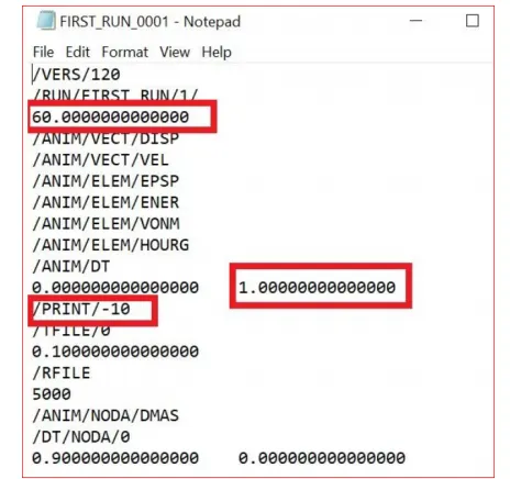
All these values we need to edit as per the given instructions.
Fig.2
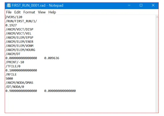
This is how our file looks like after editing the values.
- 3D meshing: - tetra mesh and hex mesh on given models.
Target tet size=5mm, hex size=10mm, tet collapse=0.15
A.Tetra meshing
Procedure -
1.Import the model .
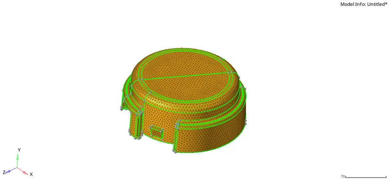
- Check any geometric errors available in model by Selecting 2D Topo view in visualization panel and click on wireframe geometry option it will show model in green color edges which means there is no any geometric errors, we can proceeding to meshing
- First create 2D mesh on all over the surface by using 2D > Automesh > select element type as trias and element size as 5 (Given) > Mesh option as shown in below image
Fig.3
- For tetra meshing, select 3D > Tetramesh > Tetra mesh > select component > Mesh option it will generate tetras inside 2D mesh
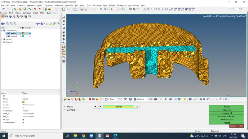
Fig.4
- Now check for tet collapse by pressing F10 or Tools > Check element > 3D > Tet collapse option. Set tet collapse value as 0.1 which is given and click on tet collapse it will shows messages of number of elements are failing for tet collapse criteria. Then click on save failed eliminating this error.
- Go to Tools > Mask > select retrieve element > Mask > reverse all then it will shown only elements which are fails for tet collapse quality also click on unmask adjacent option.
- Remesh the displayed elements using Tetramesh > Tetra remesh > remesh option as shown in image below and check again for tet collapse. It will show no error in mesh and our model is done as shown in fig.5
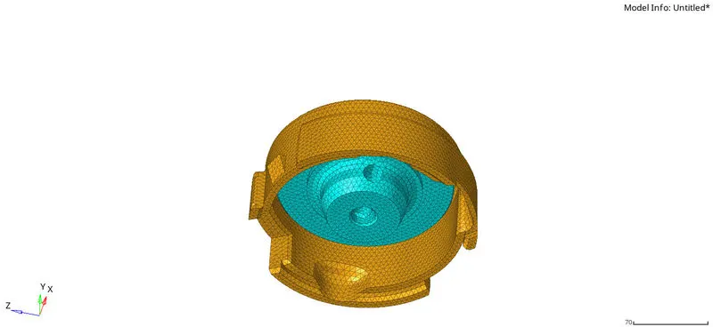
fig.5
7.3d meshing hexa mesh
Repeat class examples and, maintain the quality.
Target tet size=5mm,hex size=10mm,tet collapse=0.15.
- Import given model into hyper works GUI by File > Import > model option it will imported given model into hyperworks as shown in image below.
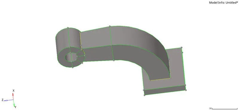
fig.6
2.This is the base of a hexa meshing component. section 2 will be seen in below figure
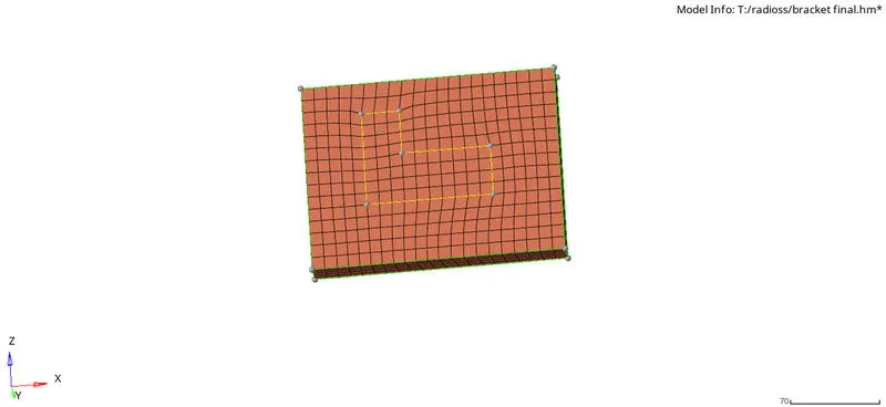
Base fig.7
3.After that, unhide arm curve surface and create three nodes on curve line then press F4 and select N1, N2, N3 nodes and click on circle centre it will create base point for spinning the elements across arm curve component.
- For creating hexa elements along the arm curve select 3D > Spin > spin elements > select 2D elements which are need to be spined along arm curve > select along x-axis > angle 90° > on spin 25 > spin – it will generate hex elements along arm curve as shown in image below.
- For hex meshing on arm straight component need to create same elements on both sides but elements are already present on one side of arm straight so we need to create same elements on opposite side for that create faces of elements by using Tools > Faces > Select elements > Find faces option as shown in image below.
- Create 2D elements on the opposite side similarly as the starting face as shown in image below.
- Go to the 3D > Linear solid > select elements from and alignment > select elements to > density 12 > solid option it will generate solid elements across arm straight as shown in image below.
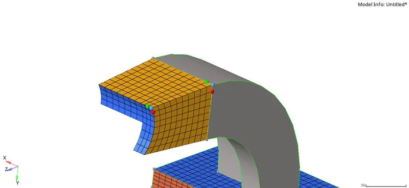
- For Hexa meshing of the boss component, unhide the geometry of boss and FE of arms straight and make the split as shown in the image below for it will match elements on arm straight and boss.
- Go to 2D > automesh and mesh the boos component with quad elements as shown in the image below.
- Create Hexa mesh by 3D > solid map > general > select source geometry none > select destination surface as base of boss > select elements to drag > Select along geometry as a node path and select nodes > Mesh option. It will generate solid Hexa mesh as shown in the image below
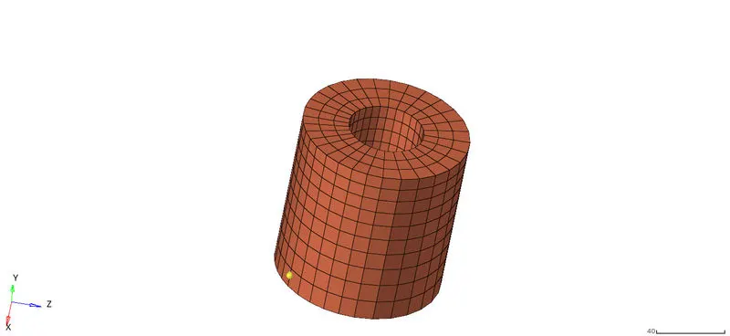
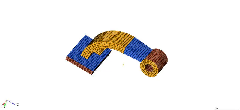
- After generating all hexa elements according to base geometry, delete the 2D elements. The final view of the model is shown in the image below. Finally check element connectivity.
Here you can see the images of all our previous steps in fig. 8,9,10,11 respectively.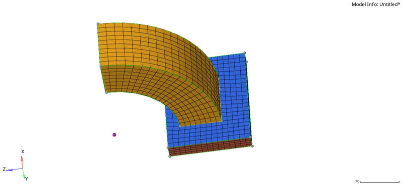
Learning outcomes :- 3D meshing : 1) Hexa meshing
2) Tetra meshing
Learned to edit radioss engine file and to calculate speed of sound in given component by using material properties of given model.
Learned to calculate elemental time steps.
Result :- Thus the given model of housing is tetra meshed and arm bracket model is hexa meshed as per given parameters and also solve the problems on time step calculations and perform editing in the engine file as mentioned in the problem statement.