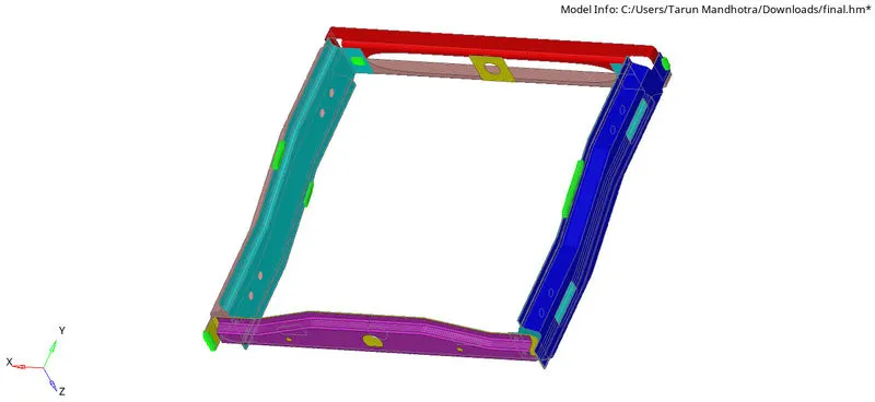
Week 9-Creation of 1D Connectors Challenge
Aim - Mesh the given component and deploy the appropriate connection.
Provided below are the quality parameters that you have to follow.
Target Element size - 5 Units
|
S.No |
Quality Criteria |
Value |
|
1 |
Aspect Ratio |
5 |
|
2 |
Skewness |
45 |
|
3 |
Warping |
15 |
|
4 |
Taper |
0.5 |
|
5 |
Min. Length |
2 Units |
|
6 |
Max. Length |
8 Units |
|
7 |
Min angle Quad |
45 |
|
8 |
Max angle Quad |
135 |
|
9 |
Min angle Tria |
30 |
|
10 |
Max angle Tria |
110 |
|
10 |
Tria % |
15 |
Create connector and Attach the various parts of the given model
- Right_Rail_2 & Front_truss_1:- Seam-Quad(angled+capped+L)
- Left_Rail_2 & Front_truss_1:- Quad elements
- Front_truss_2, Front_truss_1 & Right_Rail_1:- Spot weld with 2 Layers and 5 mm Diameter
- Front_truss_2, Front_truss_1 & Left_Rail_1:- Hexa (Adhesive)
- Rear_truss_2 & Right_Rail_2:- Bolt Connector
- Rear_truss_2 & Left_Rail_2:- Bolt Connector
- Right_Rail_1 & Right_Rail_2:- Spot-weld with Rigid Elements
- Left_Rail_1 & Left_Rail_2:- Spot-weld with Spring Elements
- Rest all the component left Join them with suitable connectors
Procedure - First of all we have to import the model from the skill Lync
website then open it in a given format and fill in the given quality criteria
and then mesh the component . after meshing we have to deploy the connections one by one
CONNECTIONS:-
- SEAM WELD CONNECTION
Steps we have to follow
1.Hide all components except right rail 2 and front truss 1.
2.1D > connectors > seam type as seam-quad(angled+cappled+L)
3.Select the node list on the front truss and components to connect.
4.Increase tolerance value to 10 and Click create and remesh the area for proper mesh flow.
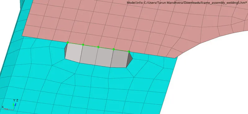
In some area where the mesh flow disturbed we have to remesh all those areas.
- QUAD ELEMENTS
Steps we have to follow
1.Hide all components except left rail 2 and front truss 1.
2.1D > Connectors > Seam and type as quads.
- Create a property for quad elements and assign.
- Select the node list on front truss and components to connect, with remesh option.
- Increase tolerance value to 10 and Click create and remesh the area for proper mesh flow.
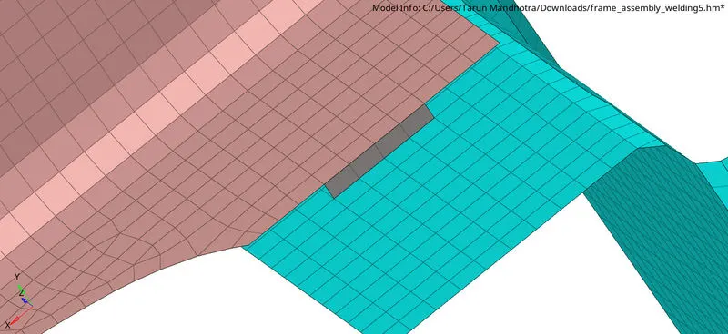
- SPOT WELD
Steps we have to follow
- Hide all components except Front truss 2, Front truss 1 and right rail
- 1D > connectors > spot type as weld , diameter as 5mm.
- Select the nodes to spot weld and components to connect with 2 layers.
- Create a property for spot welding and assign. Click create with tolerance 20.
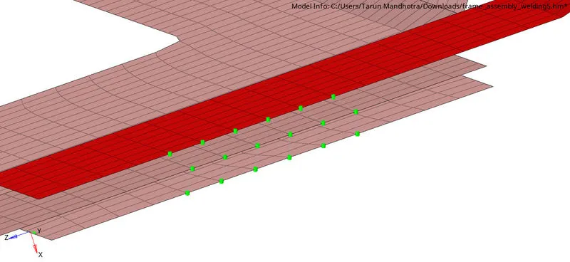
- HEXA ADHESIVE CONNECTOR
Steps you have to follow
- Hide all components except Front_truss_2, Front_truss_1 & Left_Rail_1 .
2.1D > connectors > seam type as Hexa (adhesive).
- Increase tolerance to 50 , select nodes in one component and select components to connect. Create.
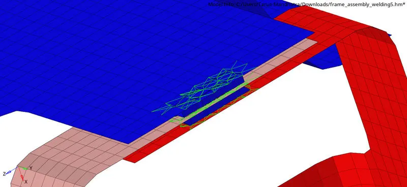
- BOLT CONNECTOR :- Here we have to create hole first then
Steps you have to follow
1.Hide the components except Rear_truss_2 & Right_Rail_2.
2.1D > Bolt type as Bolt (general).
- Select the nodes and components to connect.
- Increase tolerance to 50 and select create bolt if necessary.
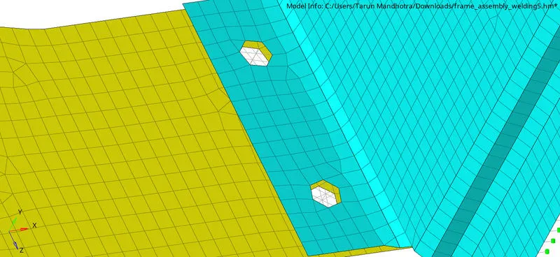
- Similar steps for BOLT connectors repeat for Rear_truss_2 & Left_Rail_2.
- SPOT WELD WITH RIGIDS
- Hide allo components except Right_Rail_1 & Right_Rail_2.
- 1D > Connectors > spot type as rigids select nodes to connect. Assign property.
- Select components to connect after increasing tolerance to 50 and create.
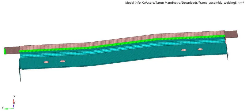
- SPOT WELD WITH SPRINGS
1.Hide all components except Left_Rail_1 & Left_Rail_2.
2.1D > Connectors > spot type as springs select nodes to connect. Assign property
3.Select components to connect after increasing tolerance to 50 and create.
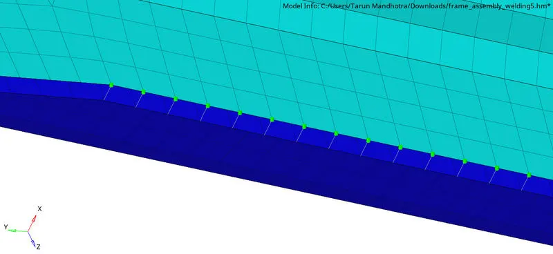
- The remaining components are connected using various methods by following the above steps.
RESULTS - We can deploy all the connection that we want in our model as per the given quality criteria .
FINAL MODEL IMAGE -