Week 12:Project 2-Meshing of Rear Wheel Holder challenge
AIM:- A back wheel panel component is given for mesh and to get the quality output as
per given quality parameters and then assign them the thickness.
Target Element Length = 5 Units
|
S.N |
Quality Criteria |
Value |
|
1 |
Aspect Ratio |
5 |
|
2 |
Skewness |
45 |
|
3 |
Warping |
15 |
|
4 |
Taper |
0.5 |
|
5 |
Min. Length |
2 Units |
|
6 |
Max. Length |
8 Units |
|
7 |
Min angle Quad |
45 |
|
8 |
Max angle Quad |
135 |
|
9 |
Min angle Tria |
20 |
|
10 |
Max angle Tria |
120 |
|
10 |
Tria % |
10 |
CAD MODEL:-
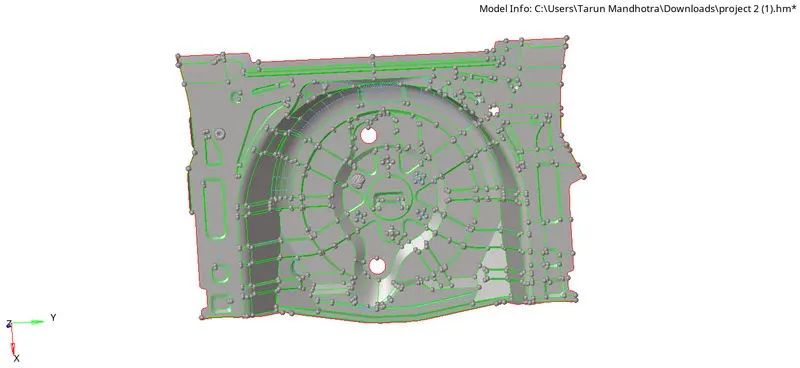
FIG.1
PROCEDURE:- As you can see in figure.1, the component has small parts that are
saved in different component files which have been organized to a single
component and the remaining has been deleted for our convenience.
After that we have to work on the topology cleanup, the panel has many missing surfaces
and or the surface are overlapping, particularly for such a case a surface has been
masked and checked for the proper surface deleted unwanted surface.
Small circles that will not meet the quality condition, so such surfaces are deleted and there are some Big circles( as seen in fig.2) 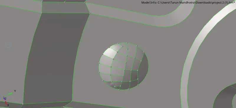
fig.2
on which we have to work on them and toggle the unnecessary lines from there, so after toggle, all those unnecessary lines you can see how's your surface looks like in fig.3
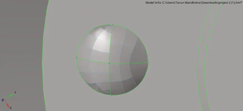
Fig.3
After clearing the all geometrical error we can proceed to the meshing in meshing we can't do it in a single shot
because the component is huge and its is complex also so for better mesh flow we have to do it one by one surface
but there are some areas which are converging so in such area we have to try to reduce the tria percentage, as you see in fig.4
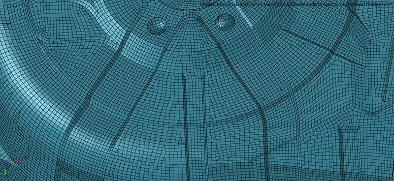
Fig.4
After completing the mesh still, there are a few areas on which we have to work on it,but still, there are some area
left with off element so for these areas, we can’t do anything because if we do so we have to defeature the surface
so either we can capture the area or we can get rid of the off element as you see in fig.5, after that we have to assign
the thickness to the component and our model is complete.
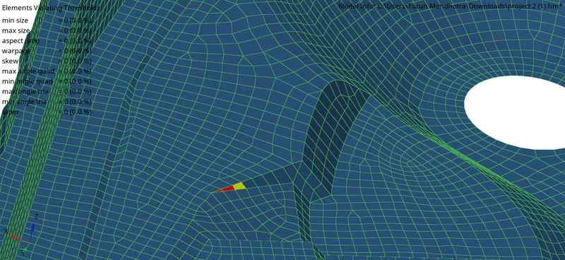
FIG.5
CONCLUSION:- As per the given quality criteria, we achieve the result.
FINAL CAD MODEL:-
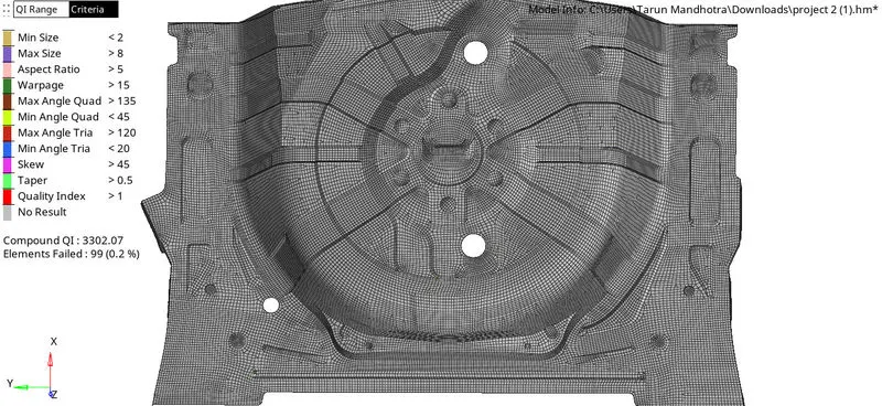
fig.6