Week 3
AIM:- Extract the mid surface of the given component and mesh it properly.
CAD MODEL:- You can see the cad model in Fig.1
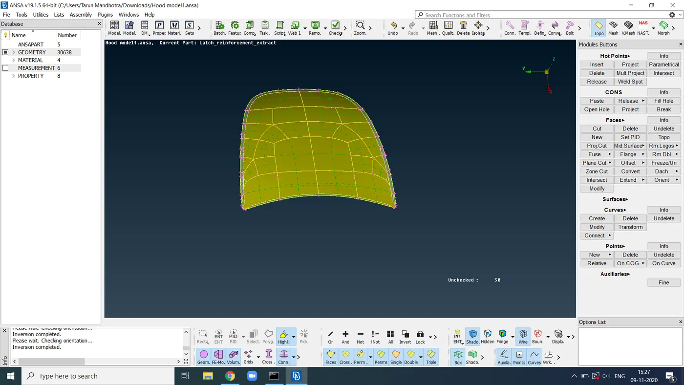
Fig.1
PROCEDURE:- Our first step is to import the cad model to the software, then we give a topo to the model(In Fig 2.1) and after that, we have to check the geometry that is in Checks manager and if the geometry (in fig 2.2) is clean then we further proceed.
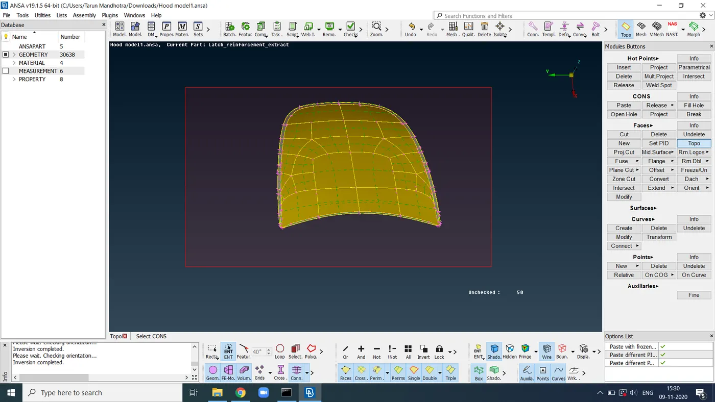
fig 2.1
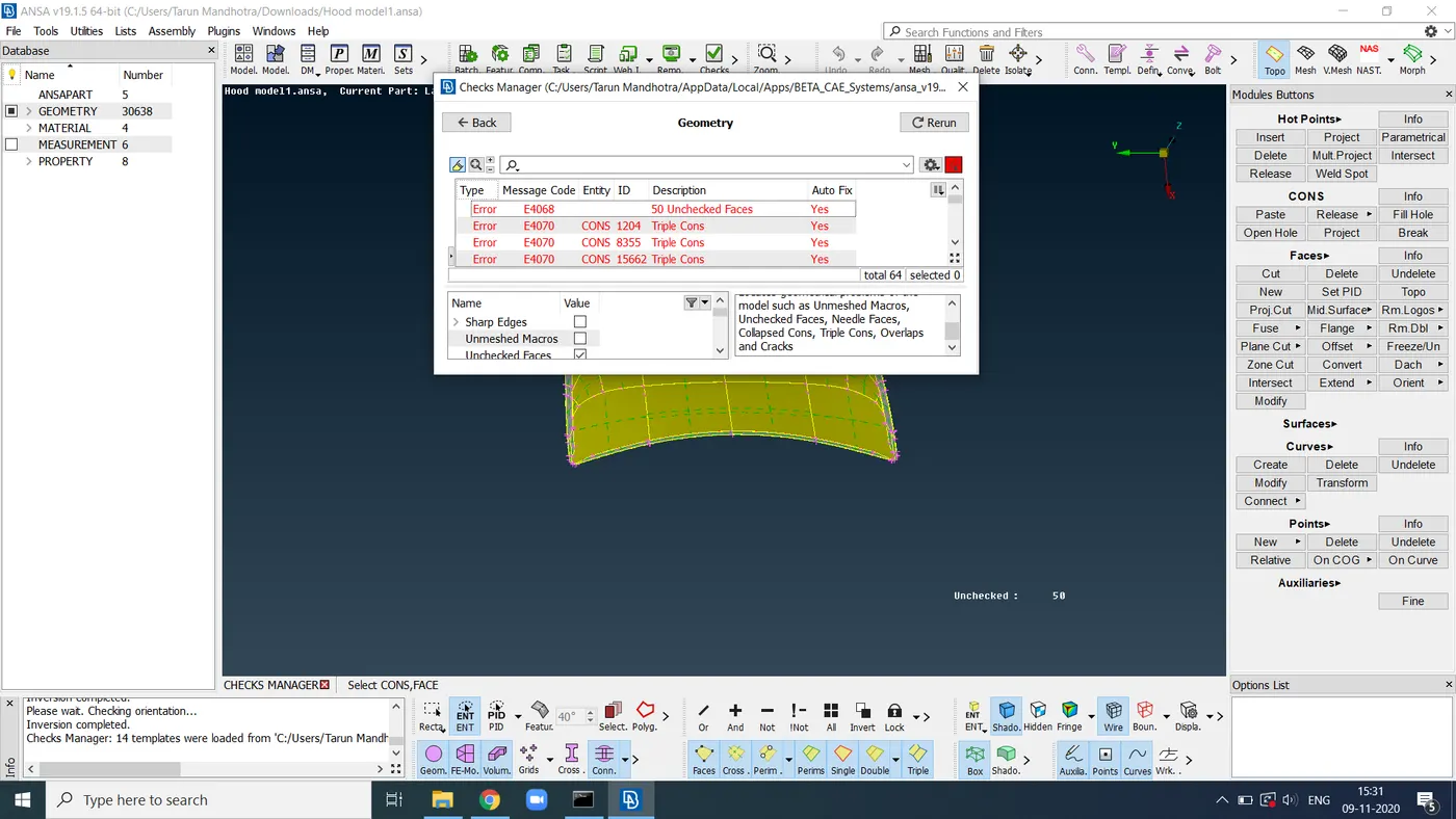
fig 2.2
Go to the PID and then change the name of the given PID as per your convenience like I give the name to all the component parts which I am working on.
After that switch on the only option which you are trying to work on, you can do this thing with the help of clicking on that bulb-like thing. (fig.3)
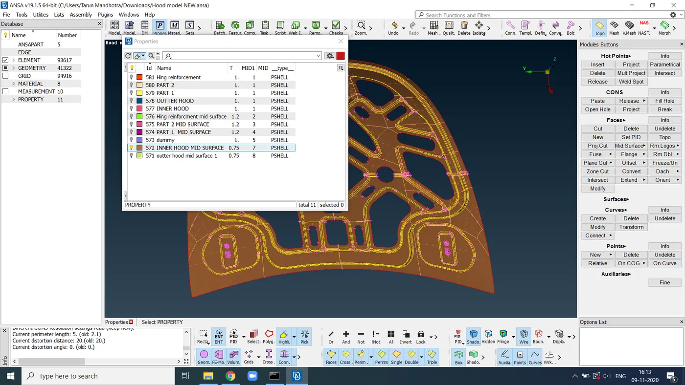
fig.3
Here in this component, we have 5 parts but I will try to demonstrate all the things with the help of only one part that is the inner hood part and that is the name that I gave to it because of my convenience.
After that we are going to take a mid surface, there is two way to taking a mid surface one is auto mid that I don’t recommend to you as a beginner, so you can go by manual mid surface for that you have to follow some steps that are go-to topo mode there you have FACES>OFFSETS>give offset value and you have a mid surface as shown in fig.4 here we gave a
value in -ve because of it's direction of the arrow.
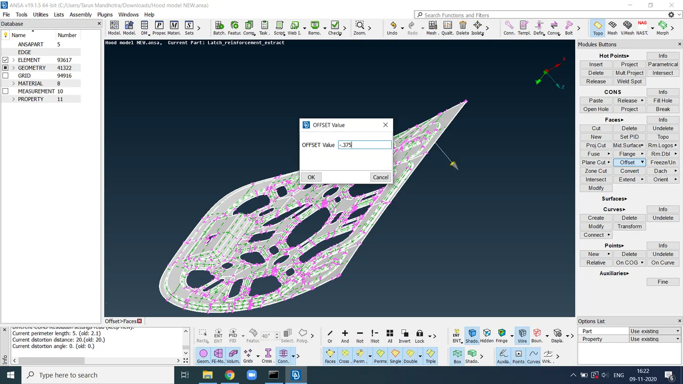
Fig.4
Now you have a mid surface so you can start your meshing, so go for mesh deck then give a length that is given as per quality criteria PERIMETER>LENGTH>give the length 5 and press Ok as shown in fig. Fig.5
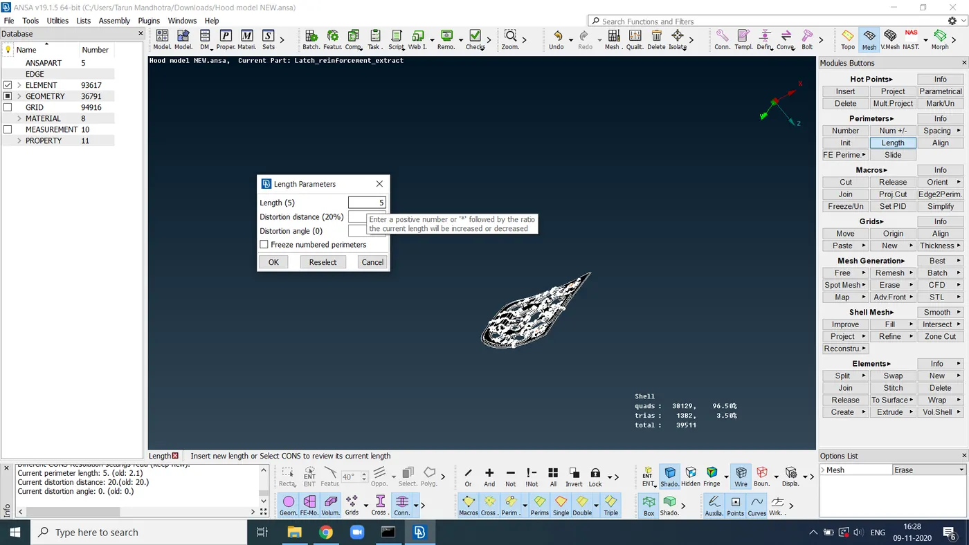
Fig.5
For meshing, I used the best mesh in this modal that is available in the Mesh generation tab, for that you have to click on the face and middle mouse click for confirmation and the mesh is generated as shown in fig.6
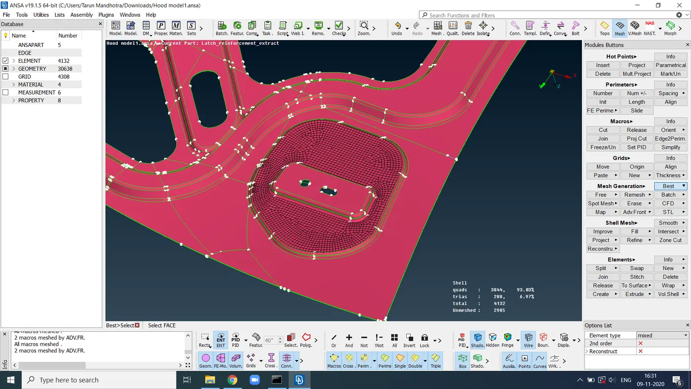
fig 6
After giving best mesh we have some trias and some quality criteria are failed.
So to get rid of these go to the element and choose any one of split,swap, join and you can eliminate them as shown in fig 7
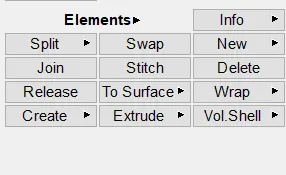
Fig 7
Whenever we made some change in element by split \swap \join make sure to don’t forget to give a smooth that is in shell mesh we can also use Re-construct but it changes the element position both of these command in Shell mesh as shown in fig8
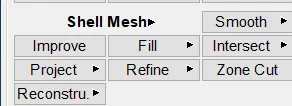
Fig 8
When we done with meshing then we go for assigning the thickness to the component by click on the draw shell as solid a shown in fig.9
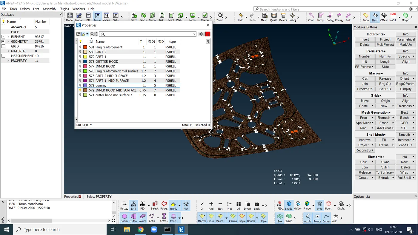
fig 9
Learning outcome:- If we summarize all things in a few words then we can say that we learn here things are:-
1.How to give a topo clean up for component.
2.How to extract a mid surface for the component.
3. How to do meshing on the component.
CONCLUSION:- So the conclusion of this is we get
a perfectly mesh component as per our quality criteria.