Assignment 5-RADIOSS Interfaces & Study of Effect of Notches Challenge
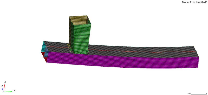
OBJECTIVE: Create the mesh for bumper assembly, mesh size should be 6mm.
1. Run the crash tube model as it is.
2. Change the Inacti=6 and run.
3. Create the type 11 contact and run.
4. Remove both notches and remove boundary condition on rigid body node then run.
5. Create a new notch in the middle, select the whole section and run.
6. Create a new notch with nodes only from opposing 2 faces and run.
Before going to run the cases there is another challenge given by the instructor is to provide the mesh to the bumper part.
after that, we have to turn off the wireframe mode in elements. The below figure represents the bumper.
fig.1
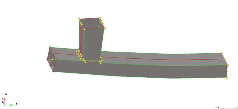
after importing the car bumper successfully we have to mesh the bumper perfectly. The below figures represent the mesh of a car bumper.
fig.2
Case -1
Run the crash tube model as it is.
for this case, we have to run the model as it is. firstly the model will look like the below figure.
after that, there is no need to change the material card and boundary condition card.
the material of type 7 will be general node to surface. all we put here is zero there is no igap, idel, icur and most all are in zero condition let us do a quick analysis and see what happened.
The below figures represent the energy error.
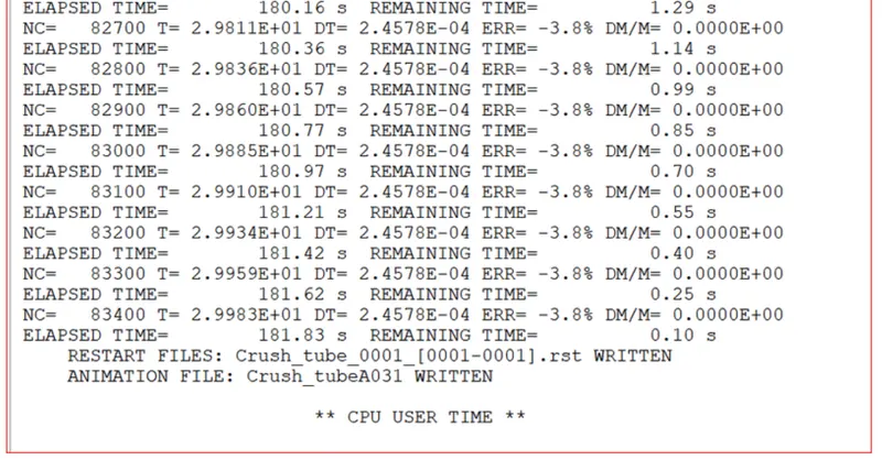
the energy error is 3.8% so it satisfied the ideal condition of 15 % we can move on it.
For case 1
INTERNAL ENERGY
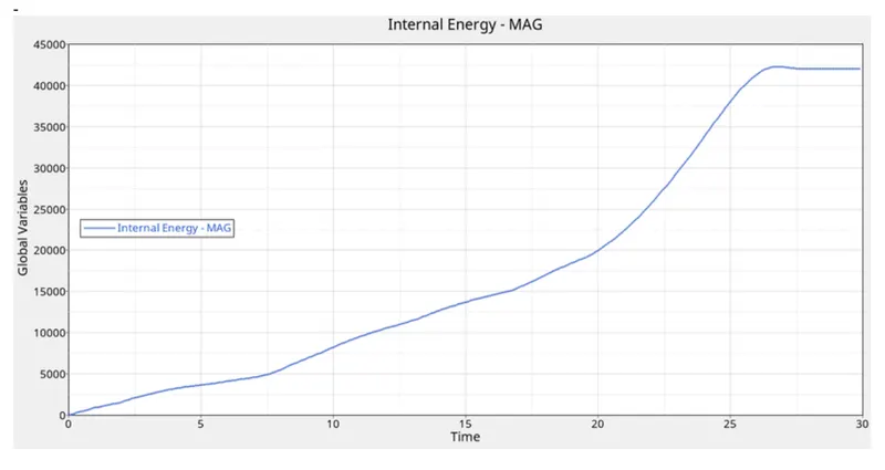
The kinetic energy is travelled along the crush tube, which means while travelling the body it has kinetic energy but, it suddenly hit the wall or any other body/ surface that kinetic energy is converted into internal energy to stop the load condition.
If we observe the graph the internal energy is less and with respect to time, it increased gradually because there is a change in energy. firstly the kinetic energy will be higher but after that, it will be converted into internal energy.
At the end of the simulation total, kinetic energy will be converted into internal energy.
if we observe the graph between 20ms to 25ms there is a sudden increase in internal energy. so the internal energy is increased after the crush tube contacts with the rigid wall, after 25ms to 30ms the internal energy is constant due to no energy is produced during the time.
TOTAL ENERGY PLOT
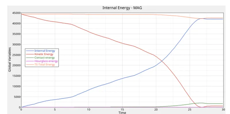
Here we observe that kinetic energy is more compared to internal energy because it is not colliding the rigid wall till 22ms of time after that it is converted to internal energy. coming to contact and total energy, the total energy is almost the same but in the latter, it is decreased up to some extent due to an increase in its contact energy.
here we can observe the hourglass energy ( artificial energy of radioss solver for balancing of energy is not developed it means it is correct and it is in the balanced condition of all energies).
Case -2 Change the Inacti=6 and run.
Inacti: Action to take if initial penetration exist.
here i took inacti is equal to 6 : gap is variable with time, but initial gap is adjusted as (the node is slightly depenetrated).
GAP! = GAP - P!-5%.(GAP-P!).
Here i took interface stiffness definition here we put istif in 4 because the master is the rigid wall so it has minimum stiffness if incase we have to put in 3, the slave nodes impacts greater stiffness it leads to breakage or it may give wrong solutions.
so here we put it in minimum stiffness of the master because it takes lesser load.
below figure represents the energy error and mass error.
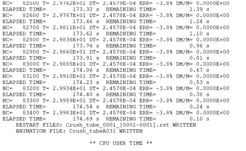
the error is 3.8 % out of 15. we can prceed the simulation why becuase it is less than the ideal error. and the mass errro is 0.00
the maximum rigid wall force is noted 1338.18N within the time of 26.6000ms. so the maximum force is acting at the end of the simulation, it means the crush tube contacts the rigid wall at the end of the simulation. so the crush tube energy is transferred to the rigid wall directly.the master and the slave node contact at the end of the simulation.
The maximum self contact force is noted at the end of the simulation due to the contact of the master and the slave node. the maximum self contact force is 1050N and the time taken by the contact force is 26ms. this is the contact force.
ALL FORCES
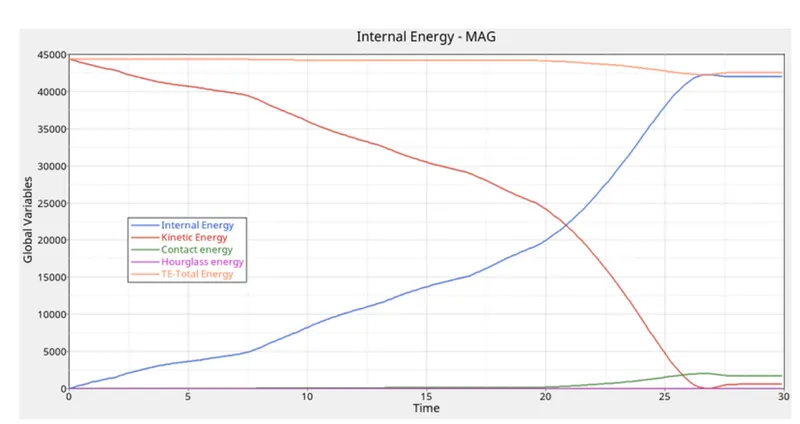
The kinetic energy is more primarily because when the body in motion due to the kinetic energy, after that it hits the rigid wall with so the kinetic energy is converted into internal energy.
we can observe here the kinetic energy is decreased in the middle of the plot because it reaches/ hits the rigid wall so the crush tube doesnt have any force acting at the end, so the kinetic energy is converted into internal energy due to the present of rigid wall.
if we observe here the hourglass energy is equal to zero we can say it is correct.
so we conclude that compared to case 1 with 2 there is not much change we observed in the plots, because of the only change is inacti to 6.
Case -3:Create the type 11 contact and run.
This interface is simulates the impact between the edge to edge or lines.
then we will check the energy error.
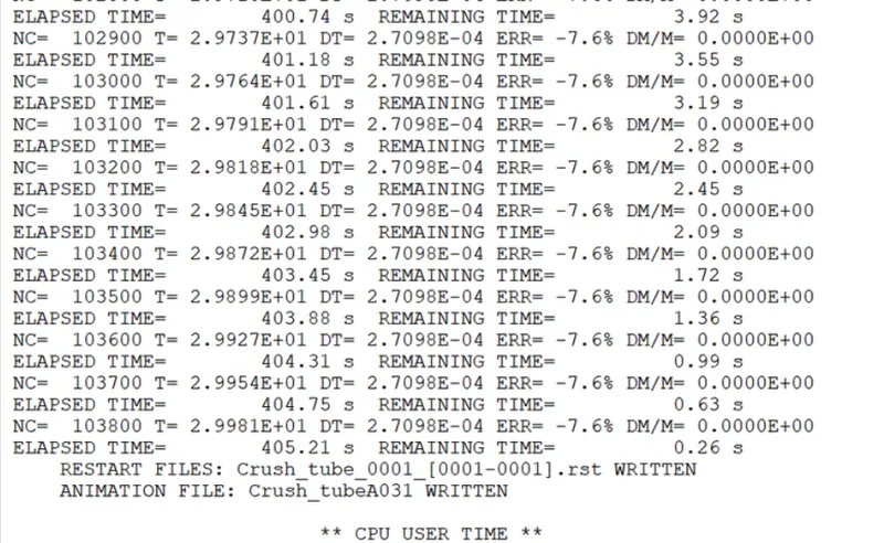
the energy error is 7.6% and the mass error is 0.000%.
The maximum rigid wall force is noted at 1532.2473N with in a time range of 252msec. the maximum deformation occurs at the end of the simulation because the contact of the master and the slave node.
the crush tube hits the rigid wall with some velocity and load due to that load it increses at the end of the simulation. if we observe the graph we can say at the begining lower the rigid wall force due to the load is acting on the crush tube itself.
ALL ENERGIES
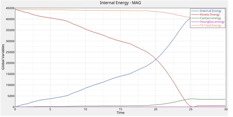
IF we noticed in this type 11 we got a kinetic energy conversion at the point of 20ms of time in x axis exactly. so, here we can say the energy conversion rate is faster in type 11 compared to type 7. the crush tube energy is contacted to the rigid wall.
Case -4 : Remove both notches and remove boundary condition on rigid body node then run.
The notches are removed and we put it in same conditions like previous case of type 11. we need to observe the energy error and mass error.
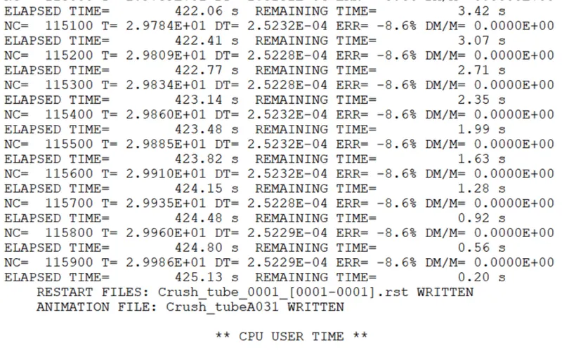
the energy errror is noted as 8.6 % and it satisfied the ideal condition of 15%. then we can proceed for analysis.
IF we can observe the cases upto 3rd case, due to the present of notches near to the middle of the crush tube. first the force impacts and deformed at that area and it moves downward. but in this case there is no notches so the deformation occurs at the end of the crush tube it means the rigidbody force is acting at the end of the crush tube due to no notches present in crush tube.
ALL ENERGY PLOT
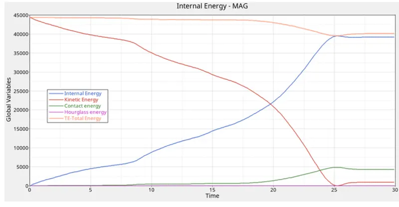
We can observed here the conversion of kinetic energy is dependent on the notches present in the crush tube. so we will observe we have more notches it will take time to convert into internal energy.
but if no notches present in the crush tube it will directly converted into internal energy due to no disturbances(notches ) present in the model.
here the ke conversion starts at before 20 milliseconds.there is no hourglass energy is produced it means our simulation is correct.
CASE-5 Create a new notch in the middle ,select the whole section and run.
WE can see the energy error in the below figure.
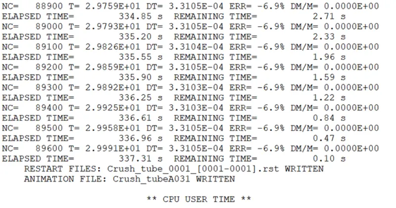
The energy error is noticed 6.9% and it is satisfied with the ideal condition of 15%.
the mass error is 0.000%.
TOTAl ENERGY PLOT
the kinetic energy is converted into internal energy at the point of 19 ms.
CASE -6 Create a new notch with nodes only from opposing 2 faces and run.
the energy error is 6.9% so it satisfied the ideal condition of 15%. the energy error is zero.
SELFCONTACT PLOT
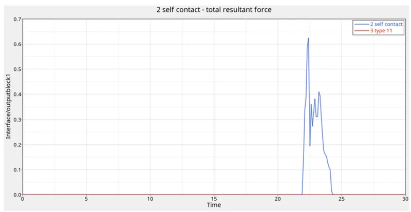
THE SELF CONTACT FORCE IS DEVELOPED AT STARTING OF TYPE 11 DUE TO THE NOTCH PRESENT IN THE MIDDLE.THE MAX SELF CONTACT FORCE IS 0.64N AND THE TIME IS 21ms.
ALL ENERGY PLOT
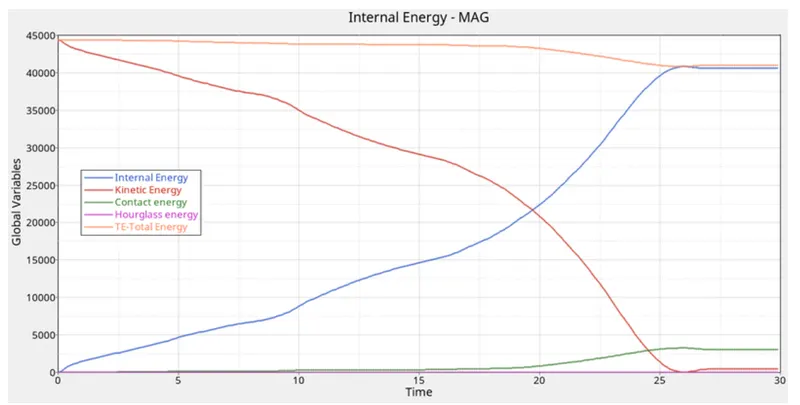
there is no hourglass energy developed so it is correct and conversion of all energies is correct.the kinetic energy is converted into internal energy.
and the summation of all energies is equal to total energy.
RESULT:
RESULT OF COMPARISON CASE 1 CASE 2 CASE 3 CASE 4 CASE 5 CASE 6
ENERGY ERROR 3.8% 3.8% 7.6% 8.6% 6.9% 6.9%
MASS ERROR 0.00% 0.00% 0.00% 0.00% 0.00% 0.00%
MAX DISPLACEMENT 2.800E^2 2.800E^2 2.665E^2 2.653E^2 2.638E^2 2.666E^2
MAX CONTACT FORCE 9.38E^1 9.38E^1 5.743E^1 6.428E^1 7.516E^1 5.263^1
RIGID WALL 200N 1338.18N 1532.247N 1180N 1500N 1210N
LEARNING OUTCOMES
How to perform radioss execution/analysis.
how to import a model
how to prepare solver deck
how many types of interfaces
contact modelling
types of contacts etc.