Assignment 3-2D Element Formulation Challenge
AIM -
|
Parameters |
Comment |
|
|
Ishell =24 |
QEPH 4 nodes shells are the best combination of cost and accuracy. |
|
|
Ismstr=2 |
Full geometric nonlinearities (default)with possible small strain formulation activation in RADIOSS Engine. |
|
|
Ish3n=2 |
Standard 3 noded shell (C0)with modification for large rotation(default) |
|
|
N=5 |
Number of integration points set to 5 for accuracy bending. |
|
|
Ithick=1 |
Thickness change is taken into account for accuracy. |
|
|
Iplas=1 |
Iterative plasticity for good accuracy. |
Questions:
Comparison of results with base simulation and improved shell element properties
1.Using the crash beam file from the previous assignment, change the run time to 55 ms.
- Change the number of animation steps during simulation to a minimum of 25 and a maximum of 60.
- Run the base simulation without any modification to element properties.
- At the end of the simulation, do the energy error and mass error checks and determine whether the results would be acceptable.
- If acceptable, Plot rigid wall forces, internal energy, hourglass energy, contact energy, total energy of the simulations.
- Change all the shell elements properties to recommended properties, save this as separate, rad files and run the simulation.
- Follow steps 5 and 6.
- Create a brief report comparing all the results from steps 5 and 6 for both simulations.
- Comment whether there is any change in the results and why there is any change in the result.
Here we have to do analysis 2 times in which once without any values and the 2nd time we have to follow some sets of instructions so we divided it in 2 cases ,so here we start with case 1 and later on case 2.
CASE - 1
1.Using the crash beam file from the previous assignment, change the runtime to 55 ms.
- Change the number of animation steps during simulation to a minimum of 25 and maximum of 60.
They are mentioned above two run time and animation steps.
Firstly open the hypermesh and set it to radioss.
The below figure represents the opening of radioss.
FIG.1
After selecting radioss then we will import a solver deck with a file. procedure for importing a solver deck. After importing the cad model it will appear like this.
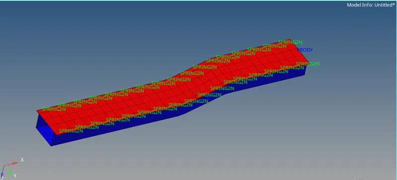
FIG.2
Step-2:After importing a file we need to edit the engine cards of time step as 55 and engine animation is 35. As per the question, I need to change the engine run to 55 and animation steps to 25-60 in between. I took 35 as my animation step.
so my time frequency is = runtime/frames = 55/35=1.5714
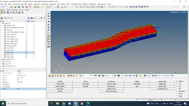
Fig.3
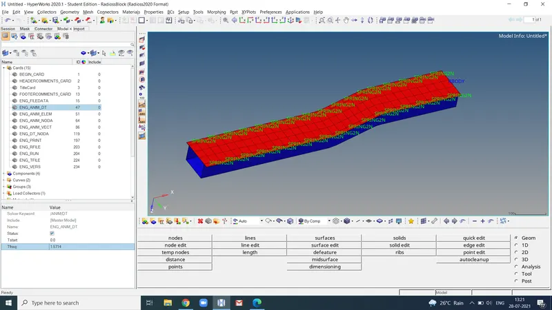
Fig.4
after changing the time step and engine run time. without changing the properties of the material and element cards we can run the simulation.
- Run the base simulation without any modification to element properties
As per the question without modifying the element properties we run the simulation by using analysis of radioss command. below figure represents the default material properties.
After that we go to the radioss , we have to save our model and in the options, we can change it into nt 4 for four cores and for faster run time.
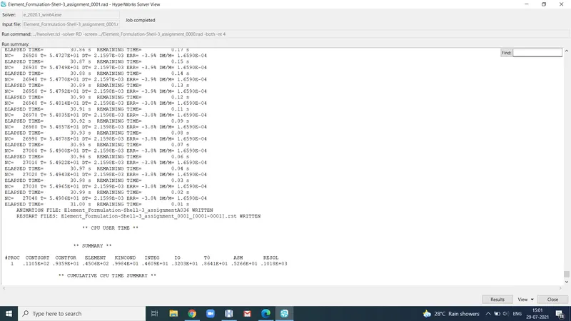
Step-4 Now we have to check the energy error and mass error.below figure represents the energy error and mass error.
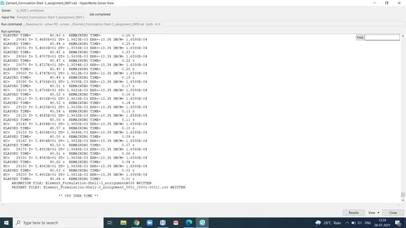
Fig.5
- Here I got energy error is 10.3% which is acceptable. for this analysis we can accept upto 15%. 2. For mass energy it is in the range of 1.6590e-04 which is also in acceptable range.
we can proceed to take the displacement and hourglass energy plots.
5.If acceptable, Plot rigid wall forces, internal energy, hourglass energy, contact energy, total energy of the simulations.
Step-5: After completing the compilation using coding we can directly press the result tab it will directly open the hyper view and where we can we observe the movement of the component.
Displacement contour plot with no property change.
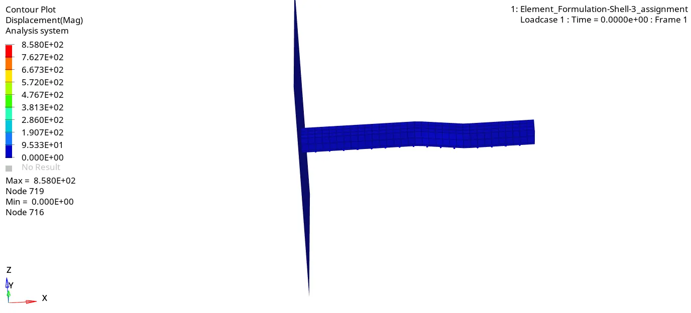
Step-6: After saving the animation file we will move on to the hypergraph 3d for plot the total energy, rigidwall forces, hourglass energy, contact energy.
for this we have to open the T01 file for plotting the graphs
Rigid wall force without changing the properties of element and material
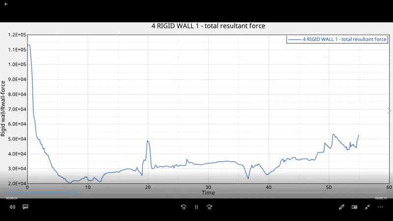
The above video represents the graph plotted between rigid wall force on y axis and time in x axis.if we observe the graph from starting to ending the rigid wall force increased and decreased a lot of disturbance , due to this we can conclude that without giving the properties it should be like this.
Step-7: After successfully plotting the graph for rigid wall force vs time.we will move on to take the graph for internal, contac kinetic, hourglass energies.below figure represents these energies.
Internal,hourglass,kinetic,contact,total energy without changing the properties
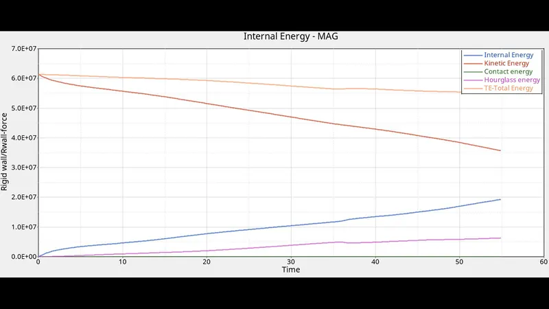
From the above graph representing kinetic , hourglass, total, contact, internal energies without changing the properties of material and element. We can conclude by observing the above graph that there is a drastic increase in hourglass energy called artificial energy by balancing the other energies.
CASE -2-CHANGING THE PROPERTIES OF A MATERIAL.
Recommended properties:
Parameters Comment
|
Ishell =24 |
QEPH 4 nodes shells are the best combination of cost and accuracy. |
|
|
Ismstr=2 |
Full geometric nonlinearities (default)with possible small strain formulation activation in RADIOSS Engine. |
|
|
Ish3n=2 |
Standard 3 noded shell (C0)with modification for large rotation(default) |
|
|
N=5 |
Number of integration points set to 5 for accuracy bending. |
|
|
Ithick=1 |
Thickness change is taken into account for accuracy. |
|
|
Iplas=1 |
Iterative plasticity for good accuracy. |
Step-8: We have to assign the above given material properties to the component.below figure represents the assigned material property.
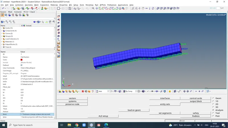
From step -1 to step -4 the same procedure, we have to follow also after assigning the engine run time -55, and frames to -35 and frequency of time to 1.57. we need to assign the properties of the element. after successfully assigning the element properties. We again went to radioss and the analysis followed the same procedure as before.
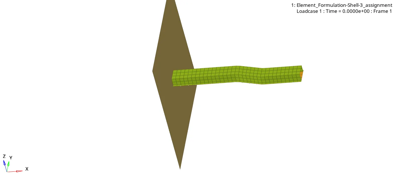
for next we will click the results it will directly open the hyperview and we can observe the displacement contour animation file.
Displacement with properties
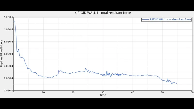
Rigid wall force with properties
Internal, kinetic, contact, hourglass, total energies with properties
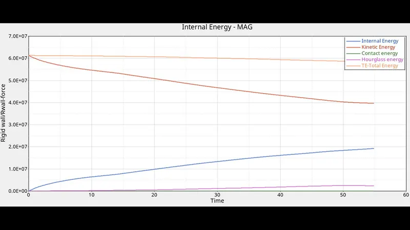
Step 9. Comment whether there is any change in the results and why there is any change in the result.
RESULT:- So we can conclude that compared to without properties graph , with properties of internal energy graph given more accurate and optimum results. so whenever we assigned the i shell, and i thick and ismstr properties the integration points calculate the displacements other energies accurately we conclude that hourglass energy is increased on the left side due to lack of integration points and without assigning of element properties. so we conclude that the hourglass energy is less in the right graph. final judgement: artificial energy(hourglass energy ) does the energies balance. and lesser hourglass energy means results will be stable and more accurate and optimum.
LEARNING OUTCOMES: So here we learnt What are types of analysis, what is time integration, what is shape function, introduction to radioss how to import a .rad file how to assign the run time and frequency time in engine run and engine dt cards.and how to save radioss file graph. how to compare the two graphs with and without properties what is hourglass energy. and a lot more.