Week 4-1D Element Creation Challenge
AIM- Mesh the Given component with the Size of 5 Units. Create 1D elements on the following component with given cross-section and DOF
- Rod element:- Translational DOF should be Constrained with RBE2 link
Cross-Section: BOX- Dimension a= 12 mm
dimension b=10 mm
Thickness t= 0.75 mm
- Beam element:- All DOF should be constrained with RBE3 link
Cross-Section: I Section- Dimension a= 8 mm
Dimension b= 10 mm
Dimension c= 8.5 mm
Thickness t1= 0.75 mm
Thickness t2= .6 mm
Thickness t3= .6 mm
- Bar element:- Constrain only x and y DOFs With RBE3 link
Cross-section: X section- Dimension DIM1= 5 mm
Thickness DIM2= 1.2 mm
Dimension DIM3= 10 mm
Thickness DIM4= 1.2mm
- & e. Apply the mass of magnitude 10 with the RBE2 link
- Join the two components with Spring elements
CAD MODEL IMAGE- Initially our model looks like this in fig.1
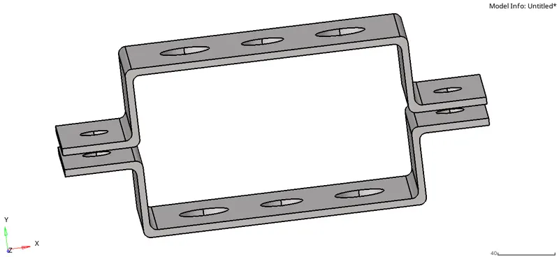
fig.1
PROCEDURE - First of all we have to download the model from a website and then we have to open it in IGES format.
Then our next step is to take a mid surface of a given component, so this how our mid -surface looks like after mid-surfacing in fig.2
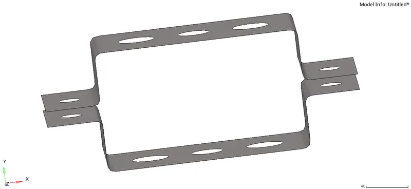
fig.2
After that, we have to create a washer that you can see in fig.3
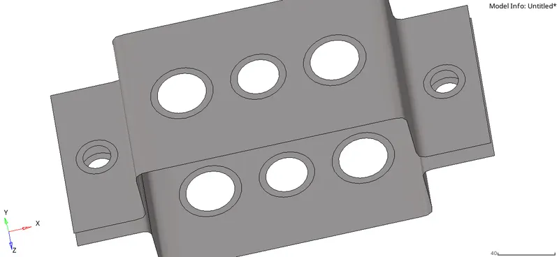
Then we have to mesh the whole model with given quality criteria ,then
For better representation, we have to arrange the no. of nodes in the same manners in fig .4
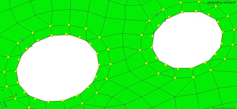
fig.4
Then as per the given quality criteria, we have to create an RBE3 and RBE2 link associate
with ROD, BEAM AND BAR a,b,c respectively as shown in fig.5
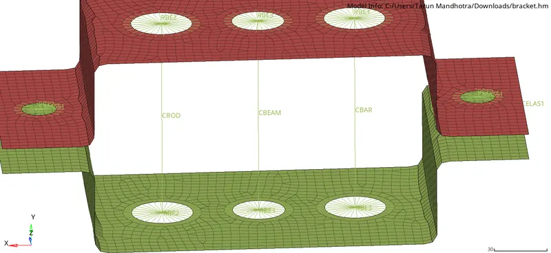
fig.5
After this, on d& e we have to Apply the mass of magnitude 10 with the RBE2 link.
And on f we have to Join the two components with Spring elements as shown in fig.6
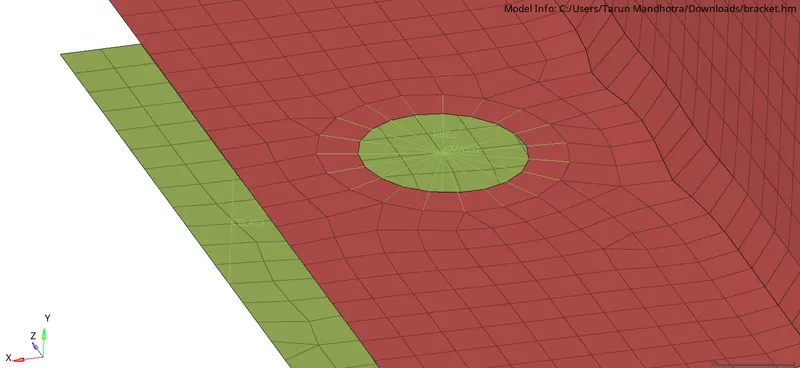
fig.6
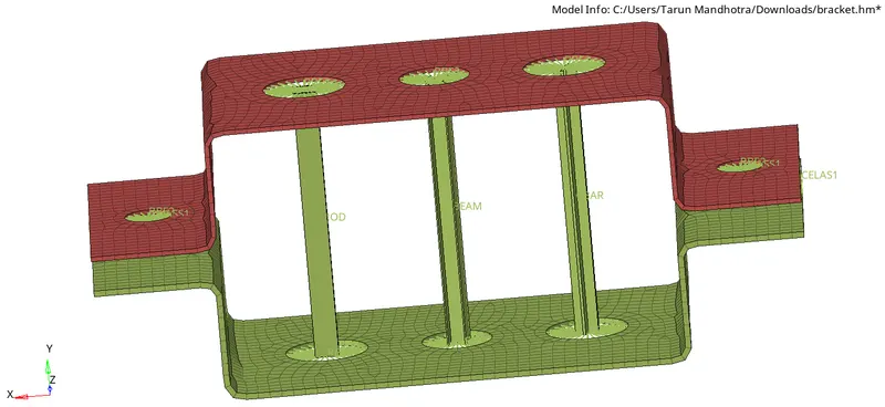
When we done with our work in the end we have to enable 1d element and 2d traditional element into detailed representation a shown in final image.
RESULT- As per the given quality criteria we achieve whatever we want in this model.
FINAL MODEL IMAGE- This is how our model looks like when it’s complete in fig.7