Design and Assembly of YATCH
AIM : Design, Model and Assemble the YATCH using SOLIDWORKS.
OBJECTIVE :
- Import the Blue Prints of the YATCH in the SOLIDWORKS.
- Design and Model the parts of the YATCH in PART DESIGN.
- Assemble the Modeled parts of the YATCH in the ASSEMBLY.
- Give the appropiate Apperance to the YATCH and Render using PHOTO VIEW and SOLIDWORKS VISUALIZE.
INTRODUCTION :
A yacht is a sail or power vessel used for pleasure, cruising, or racing. There is no standard definition, so the term applies to such vessels that have a cabin with amenities that accommodate overnight use. To be termed a yacht, as opposed to a boat, such a pleasure vessel is likely to be at least 33 feet (10 m) in length and have been judged to have good aesthetic qualities.
Originally, all yachts were made of wood, using a wooden keel and ribs, clad with planks. These materials were supplanted with iron or steel in steam yachts. In the 1960s fiberglass became a prevalent material. These materials and others continue in use. Whereas yachts of 79 feet (24 m) and below may be constructed of fiberglass, larger yachts are more likely to be constructed of steel, aluminium or composite fiber- reinforced plastic.
DESIGN :
Design considerations for a cruising yacht include seaworthiness, performance, sea kindliness, and cost of construction, as follows:
Seaworthiness addresses the integrity of the vessel and its ability to stay afloat and shelter its crew in the conditions encountered.
- Performancehinges on a number of factors, including the waterline length (longer means faster), drag in the water (narrower hull with smooth appendages), hull shape, and sail shape and area.
- Sea kindlinessis an indicator of steering ease, directional stability and quelling of motion induced by wind and waves.
In this challenge the DESIGN of YATCH in solidworks as follows :
- design and model the individual parts of the yatch.
- assemble the parts by using appropiate mates relation.
the following parts of the YATCH are :
- HULL
- SUPER STRUCTURE
- FRONT SEAT
- MIDDLE SEAT
- REAR SEAT
- RADAR
- RADAR MAST
- GARAGE DOOR
- PROPELLER
HULL :
A hull is the water tight body of ship or boat. The hull may open at the top (such as a dinghy), or it may be fully or partially covered with a deck. Atop the deck may be a deckhouse and other superstructures, such as a funnel, derrick, or mast . The line where the hull meets the water surface is called the waterline.
the following major tools used in the design and model of the hull part :
3D sketch : this is used to draw a sketch in space and on the surface.
Curve Projection : this is used for the projection of the curves made in different planes to create an intersected curve.
Surface Extrude : this is used where the extuded surface has to be very thin thickness.(i.e line thickness)
Surface Loft : It is used to create a surface using profile and guide curves.
Sweep : It helps to create tube like structure by following the required path line.
Helix/ Spiral : It helps to create the structure like spring with the following inputs of Pitch or Height and revolutions.
Surface Knit : It is used to join the multiple surfaces to form single surface and convert it into solid.
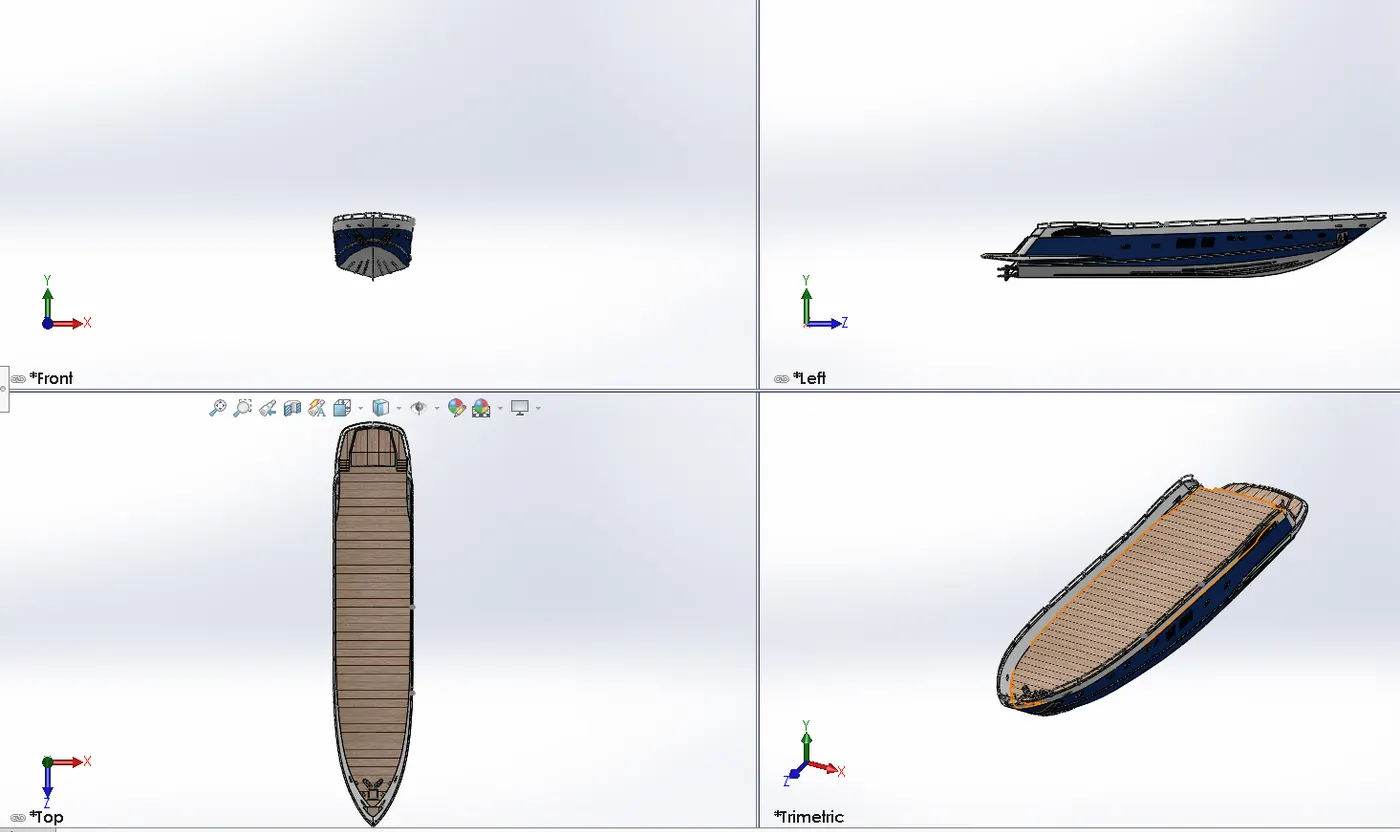
In the below image you can see the Hull part
GARAGE DOOR :
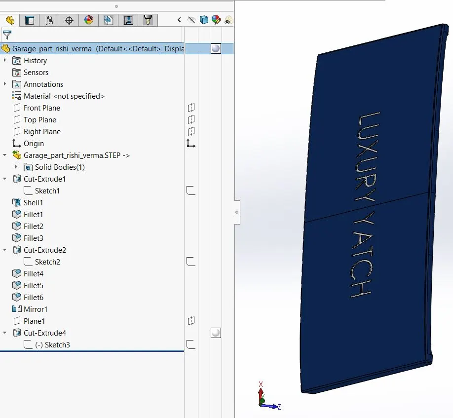
Garage is used to store the equipment or vehicles. design of the part is extracted out from the hull to make garage door by using SPLIT ENTITIES.
Garage door is modeled as different part from the splitted part of the HULL.
the following image shows a preview of the garage door.
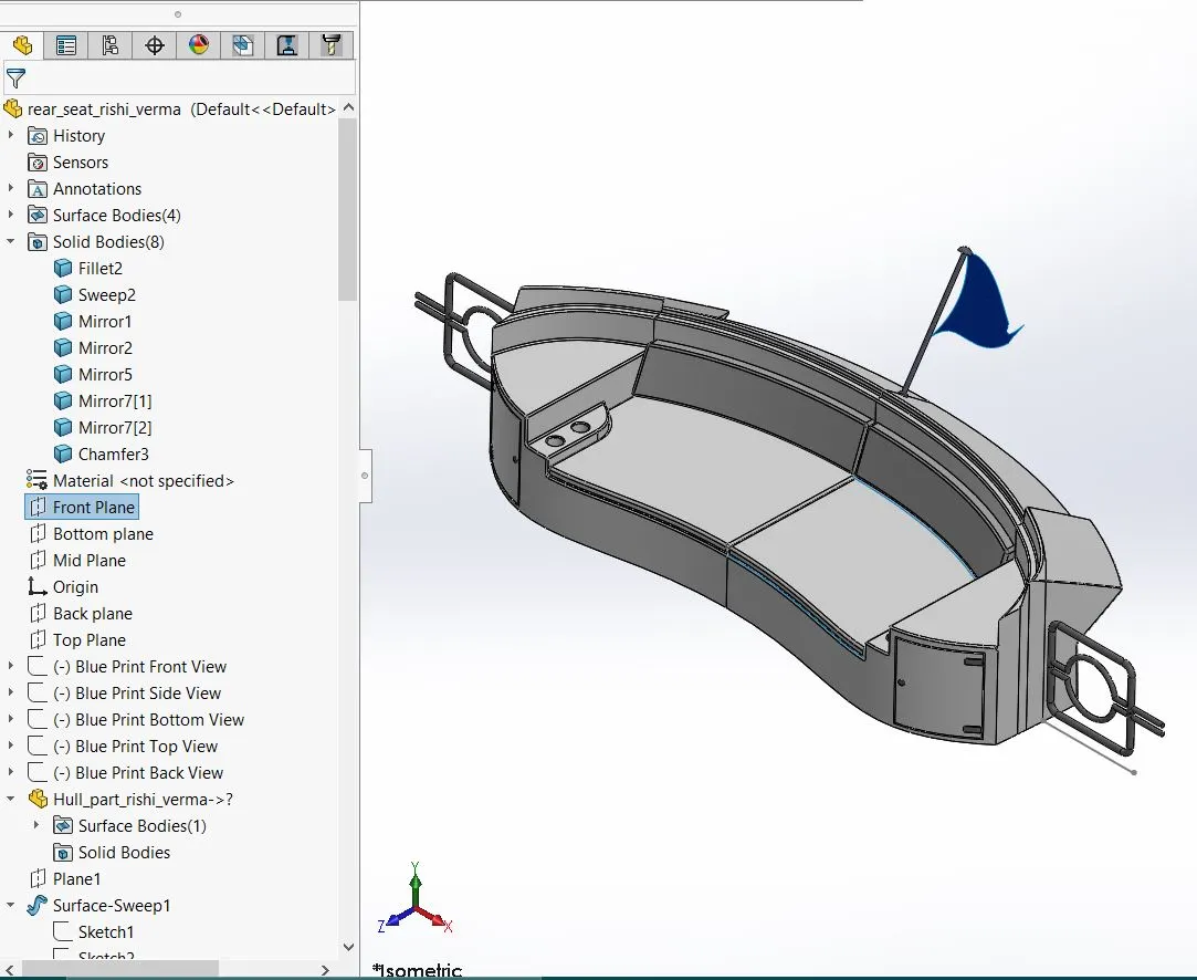
Front, Middle and Rear SEATS :
Seats are used for the Resting purpose in the Yatch.
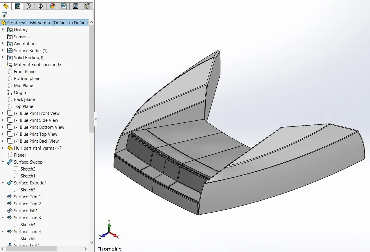
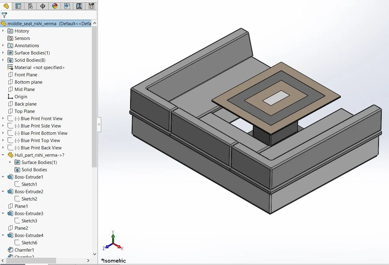
the design of the seats are made using the blue prints and modeled using feature tools. Dome option is used to get the cusion like curve surface.
the following image shows the preview of the seats
FRONT SEAT
MIDDLE SEAT
REAR SEAT
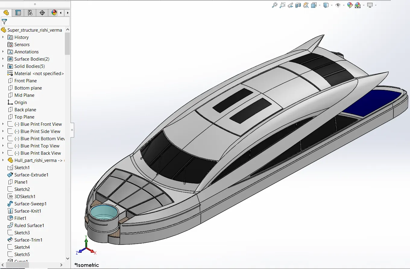
SUPER STRUCTURE :
A superstructure is an upward extension of an existing structure above a baseline. This term is applied to various kinds of physical structures such as buildings, bridges or ships having the degree of freedom zero.
the design of the super structure is the complicated part among the other parts. It is designed with the help of Blue Prints using sketch and surface tools.
the tools are mainly used for the design are :
Ruled surface :
it is used to obtain the extruded surface perpendicular to the plane and can be titled in certain angle.
Surface Trim : It is used to keep or remove the surface area of the intersecting surfaces.
Extend Surface : It is used to Extend the edge of the surface with the distance or selection edge provided.
the following image shows a preview of the super structure:
RADAR and RADAR MAST :
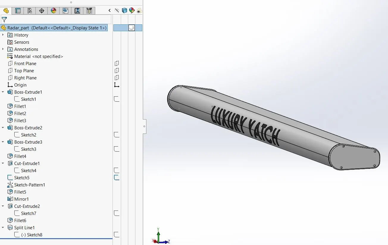
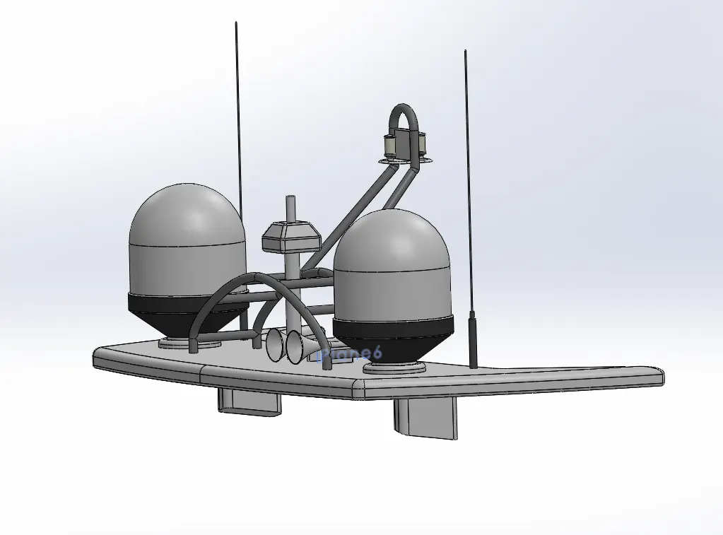
Radar is a detection system that uses radio waves to determine the range, angle, or velocity of objects. It can be used to detect aircraft, ships, guided missles, motor vehicles, weather formations and terrains . A radar system consists of a transmitter producing electro magnetic waves in the radio or micro waves domain, a transmitting antenna , a receiving antenna (often the same antenna is used for transmitting and receiving) and a reciever and processor to determine properties of the object(s). Radio waves (pulsed or continuous) from the transmitter reflect off the object and return to the receiver, giving information about the object's location and speed.
Radar mast is a setup which helps to work the radar system.
Design of these parts are done individually with the help of Blue Prints, the tools mainly used in the parts to modeled:
Revolve : the tool is used to create a cylindrical structure using a closed sketch with a centre of axis for rotation reference.
Shell : It is used to create a shell structure from a solid body by providing the thickness of the walls.
the following images shows the radar system :
PROPELLER :
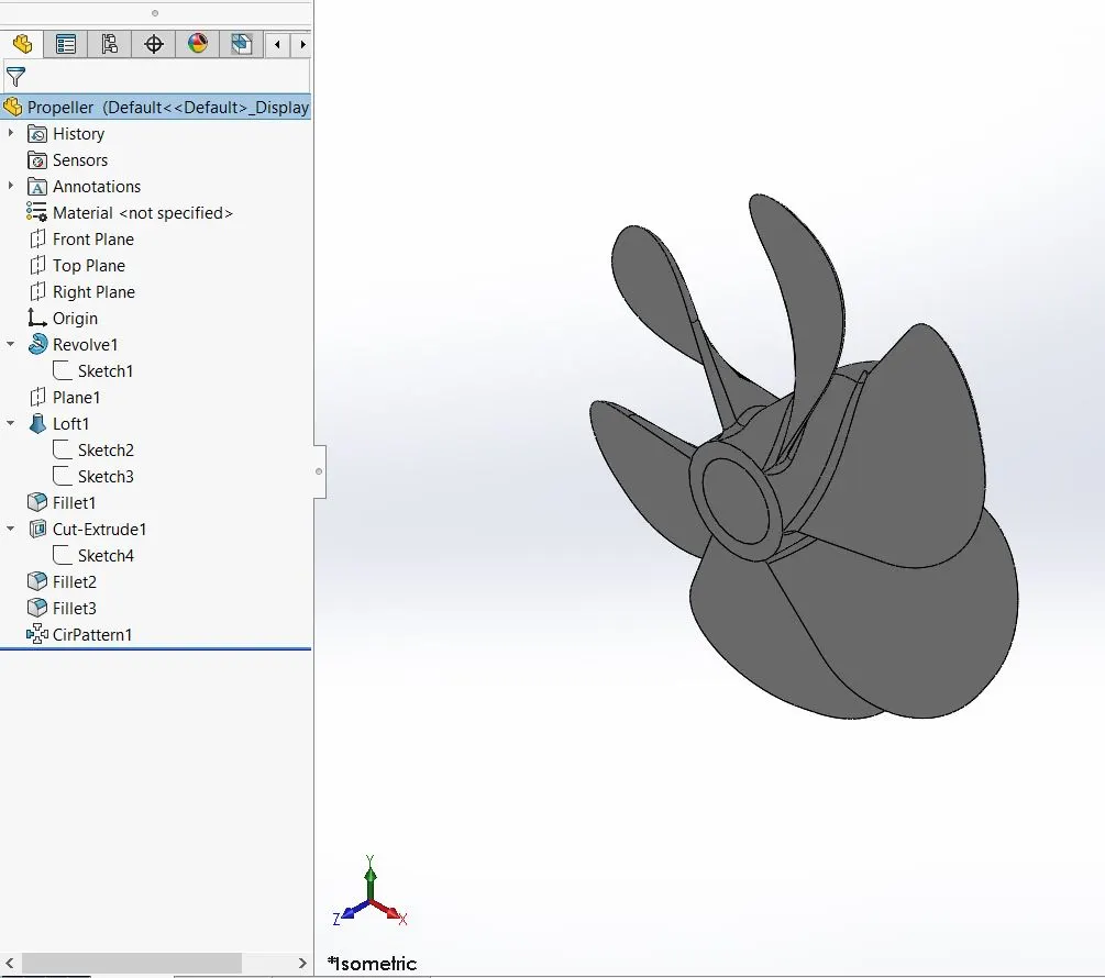
A propeller is a device with a rotating hub and radiating blades that are set at a pitch to form a helical spiral, that, when rotated, performs an action which is similar to Archimedes screw. It transforms rotational power into linear thrust by acting upon a working fluid, such as water or air.The rotational motion of the blades is converted into thrust by creating a pressure difference between the two surfaces. A given mass of working fluid is accelerated in one direction and the craft moves in the opposite direction. Most marine propellers are screw propellers with helical blades rotating on a propeller shaft with an approximately horizontal axis.
the main tools used in the design of the propeller are :
- surface extrude.
- extrude cut.
- loft surfaces.
preview of the Propeller :
ASSEMBLY :
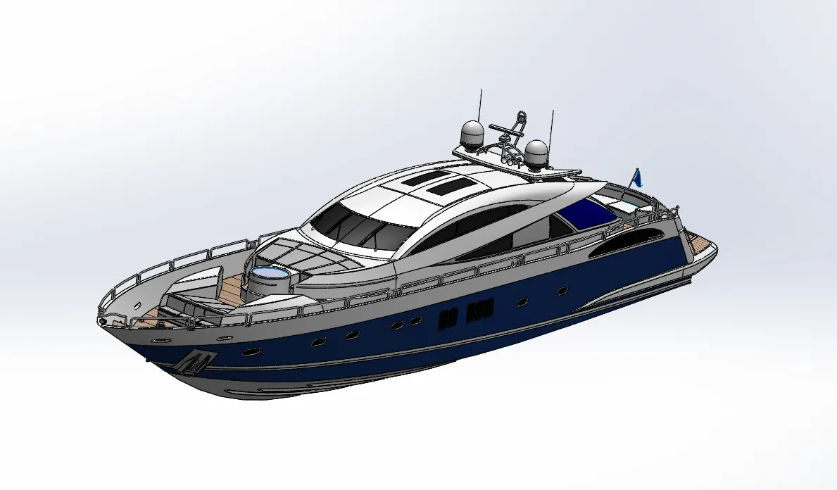
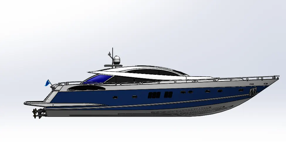
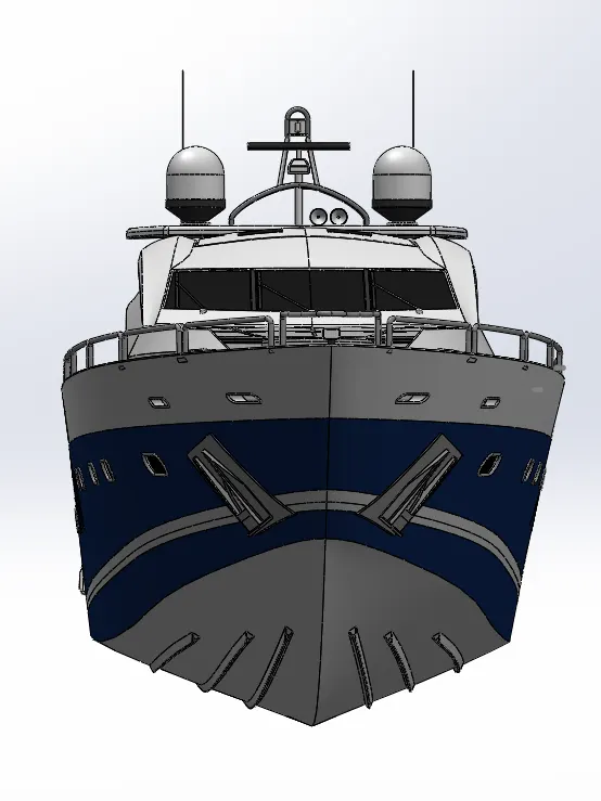
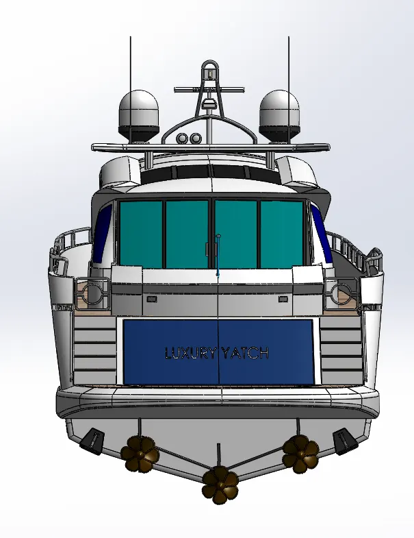
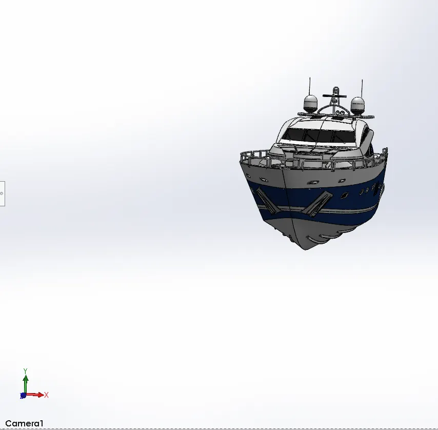
As all the parts are designed using solidworks part, now in the Assembly is used to assemble the parts of the YATCH by giving appropiate MATES with required realtive conditions.
YATCH is assembled in the assembly workbench with fix position by the help of applying mates.
RENDERING :
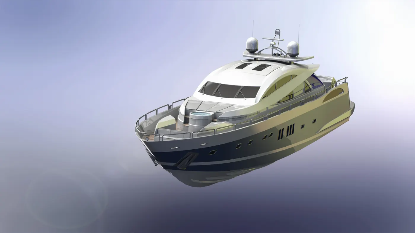
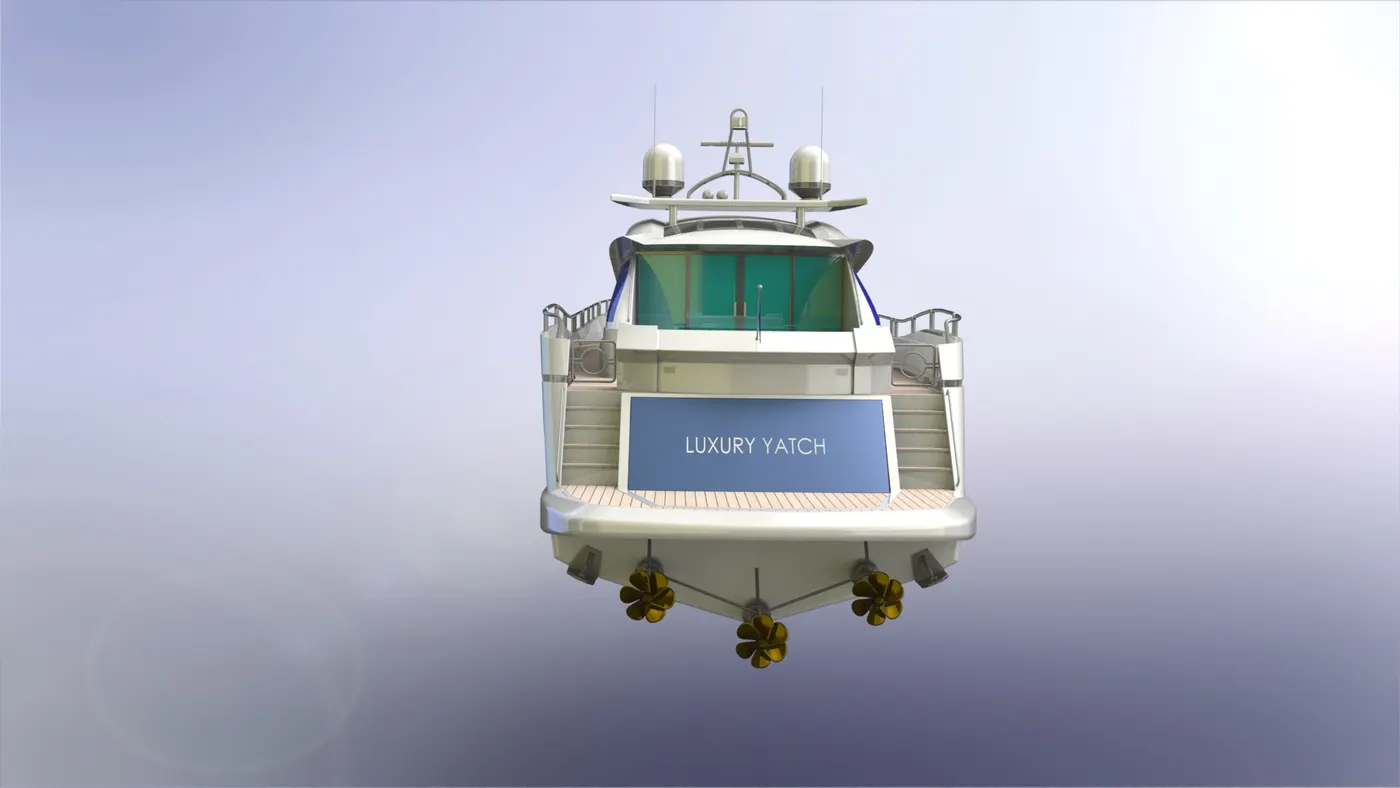
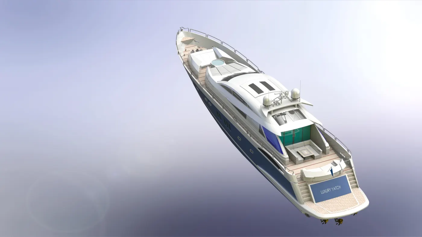
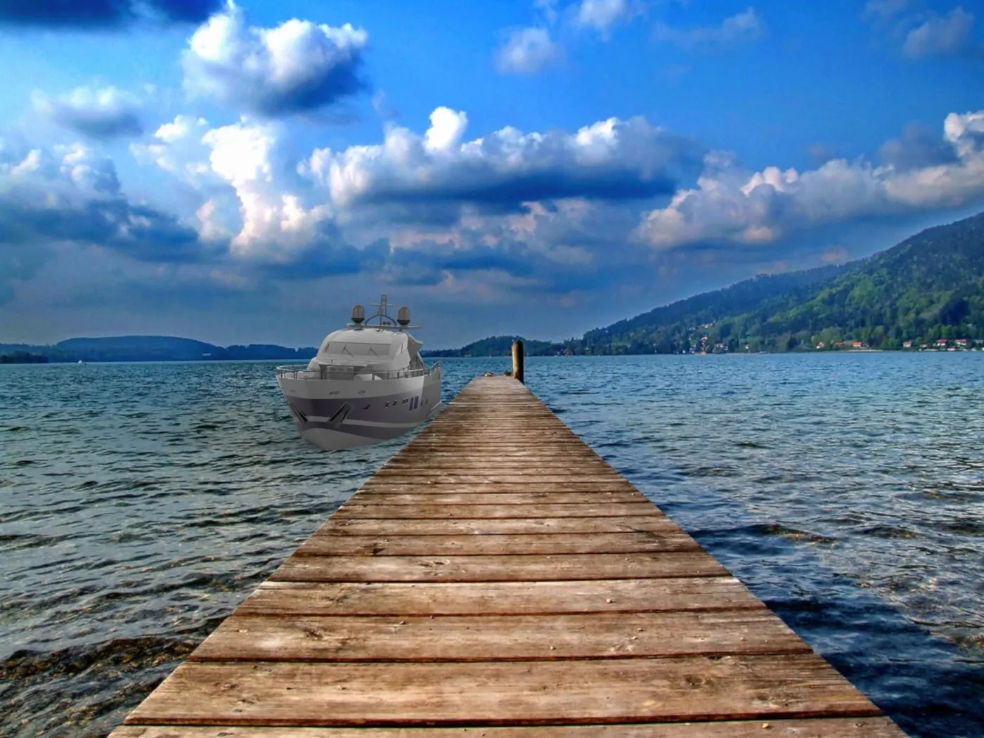
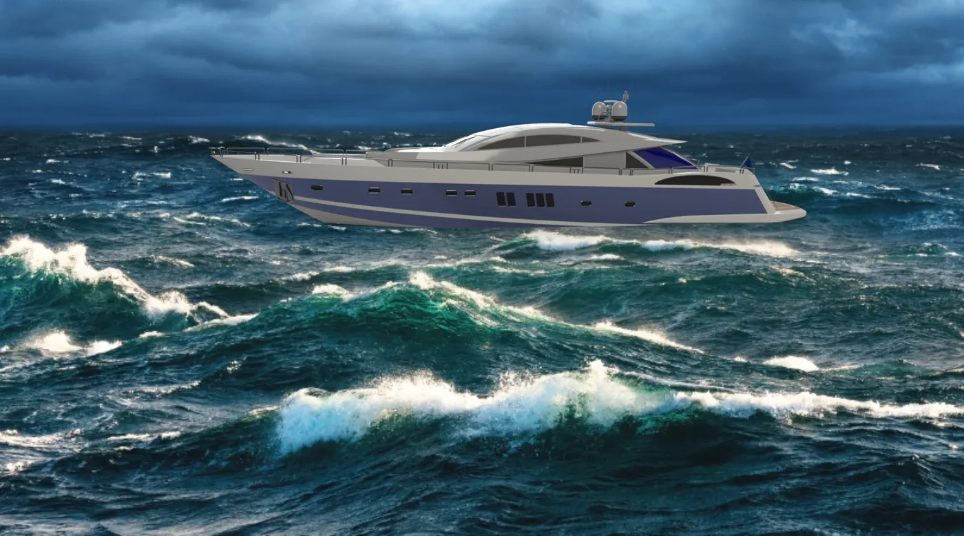
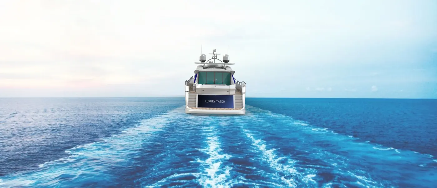
Apperances to the following parts of the YATCH as per the suitablity is applied and the rendering of the following YATCH is done in PHOTO VIEW 360 AND SOLIDWORKS VISUALIZE.
camera setup, background scene setup, back plate and the position of the yatch made and the final render with high quality is given for output file.
the RENDERED IMAGES of the YATCH in both the workbench are :
PHOTO VIEW 360
SOLIDWORKS VISUALIZE :

CONCLUSION :
The YATCH is Designed, Modeled and Assembeled in the solidworks.