Design and Assembly of CHOPPER BIKE
AIM : Design, Assembled and Render the Chopper Bike using SOLIDWORKS.
OBJECTIVE :
- Sketch the following parts design in 2D by understanding the suitable view planes with dimensions using SKETCH tools.
- Convert the 2D drawing into 3D model using FEATURE tab tools.
- save the model components and open assembly in solidworks.
- Import the following components in the Assembly in solidworks and assemble it using Assembly tools by understanding use of suitable planes for reference.
- open photoview 360 in solidworks to set the Appearances, scenes, cameras, lights and Enviornment for final rendering process.
- Render the model with appropiate quality and enviornment and proceed the same procedure in the VISUALIZE in SOLIDWORKS for more accurate realisitc rendering.
PROCEDURE AND EXPLAINATION :
the following parts are modeled for the Chopper bike are :
- Transmission Belt.
- Side Kick Stand.
- Front Fender.
- Front Wheel.
- Back/Rear Fender.
- Back/Raer Wheel.
- Oil Tank.
- Chain.
- Foot Pedals.
- Front Fork.
- Chasis.
- Engine.
- Gas/Fuel Tank.
TRANSMISSION BELT :
This is used to transmit the energy generated in the engine to the gear box of the bike.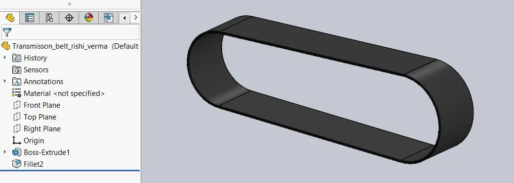
Procedure followed :
- Open the solidworks and click on new part, choose the required plane and start sketching.
- In this case, select the front plane and start skecth by giving appropiate dimenisons using sketch tools.
NOTE : the sketches should be fully defined. - the OFFSET command is used to create duplicate of sketch by varing in dimensions.
- exit from skectha and go to FEATURES tools, use EXTRUDE command to convert the 2D sketch into 3D model by applying required dimensions.
- FILLET is applied to the edges for the smooth curve surface to occur and then save the model as a part.
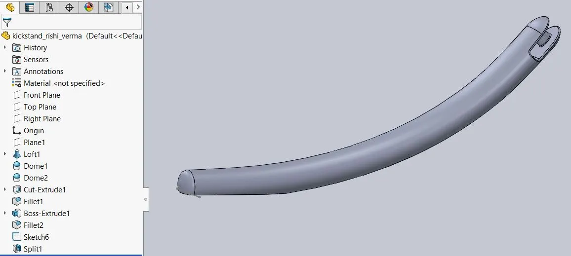
SIDE KICK STAND :
the side kick stand is used to support the Bike in stationary position, it keeps the bike not to fall while no other support is provided.
Procedure Followed :
- Open the solidworks and select the new part, select the plane and start skecthing.
- using the required planes as reference view and the required tools from the sketch tools create the sketch, give the dimensions using smart dimensions to fully define the sketch created.
- In the sketch tools we used spline tool to create a curve like line path and trim tool for removing /edit the extra unneccesary line or skecth part.
- FEATURES > REFERENCE > PLANE tool is used to create reference planes to created sketch at required points in space.
- FEATURES > LOFT command is used to create the complex geometry, it helps to create extruded ellipse part by following the complex spline path.
- FEATURES > EXTRUDE CUT is used to cut the bottom edge of the stand to give a flat surface for the bottom face of stand.
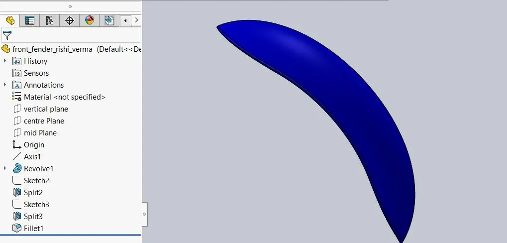
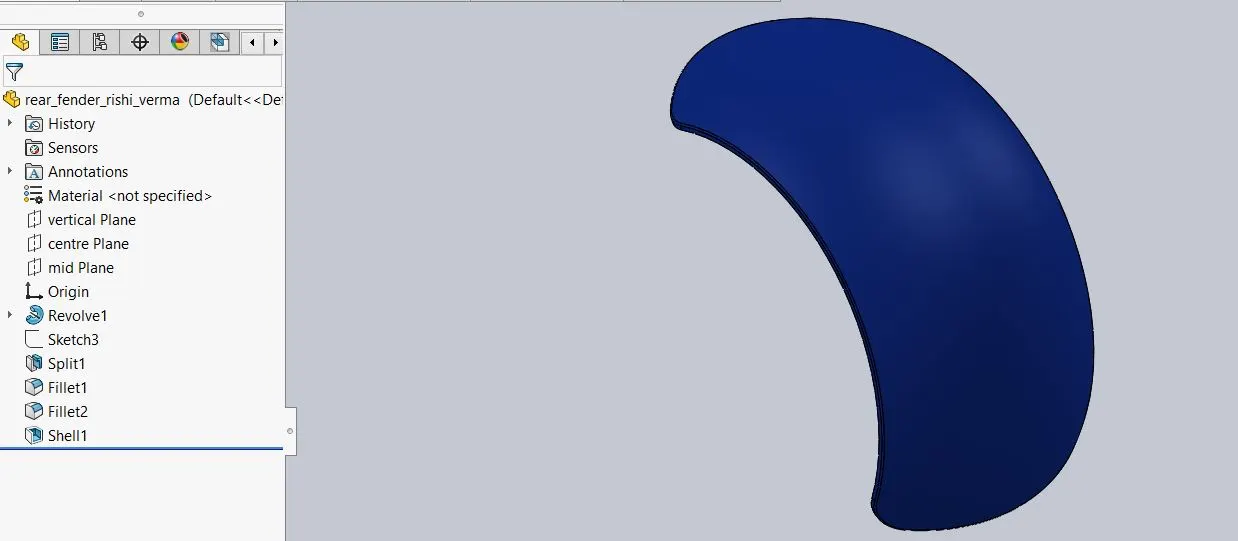
FRONT FENDER AND REAR FENDER :
these parts are placed over the wheels to protected the remaining parts of bike and the rider from unwanted dirt and water which comee when wheel is rotating while in motion.
it is mounted with the front fork and chasis support.
MAIN FEATURES USED :
- revolved boss
it is used to create a circular kind of part which takes reference axis as axis of rotation. - split
it is used for the removal of material from existing part to get an appropiate shape to the part. - fillet
it is used to give the curve smooth finish surface to the sharp edges of the parts. - shell
it is used to assign the thickness to the part and removes the unwanted material beyond that thickness.
FRONT WHEEL AND BACK WHEEL :
wheels are group of circular components include brake components, tyre,chain spoket and alloys rim.it helps to give motion to the bike by rotaion.
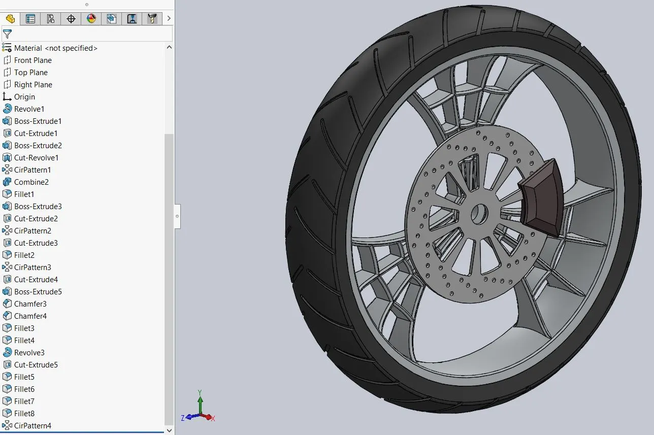
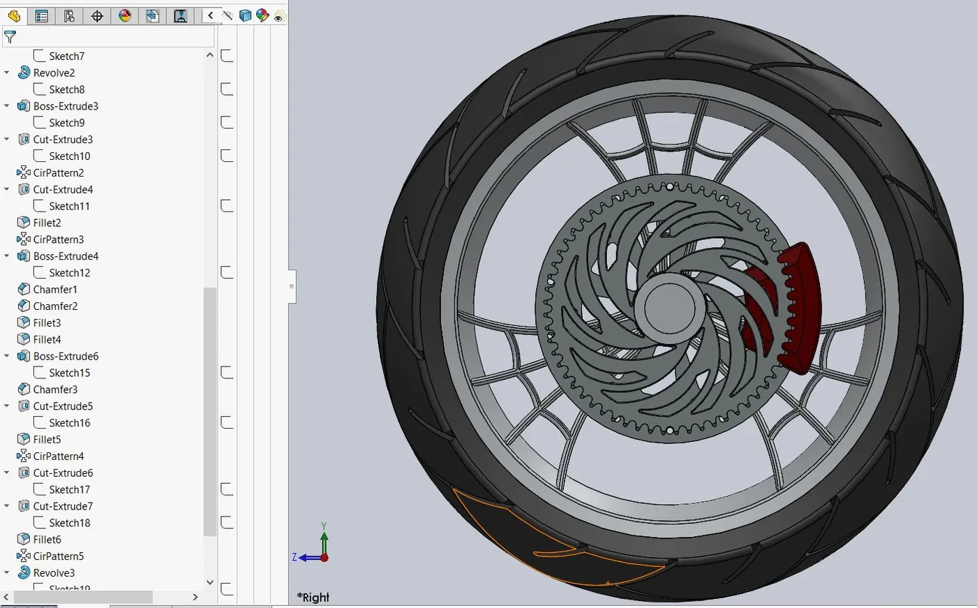
Main Features Used :
- sketch
- revolve boss
- trim
- fillet
- boss extrude
- revolve cut
these is used to remove or cut material in circular pattern. - linear pattern
it is used to sketch followed a pattern to give multiple copies. - chamfer
it is used to create a bevel feature along with edge. - sketch fillet
it is used to give fillet region in the sketch. - cut extrude
this cuts a solid model by extruding the sketch. - circular pattern
this is used to follow sketch in circular pattern while creating multiple copies. - planes
reference plane are used to create sketch in any point in the sketch by creating a new temporary plane.
CHAIN :
It is the part which is used to transfer the rotational energy from transmission to back wheel sproket to provide motion to bike.
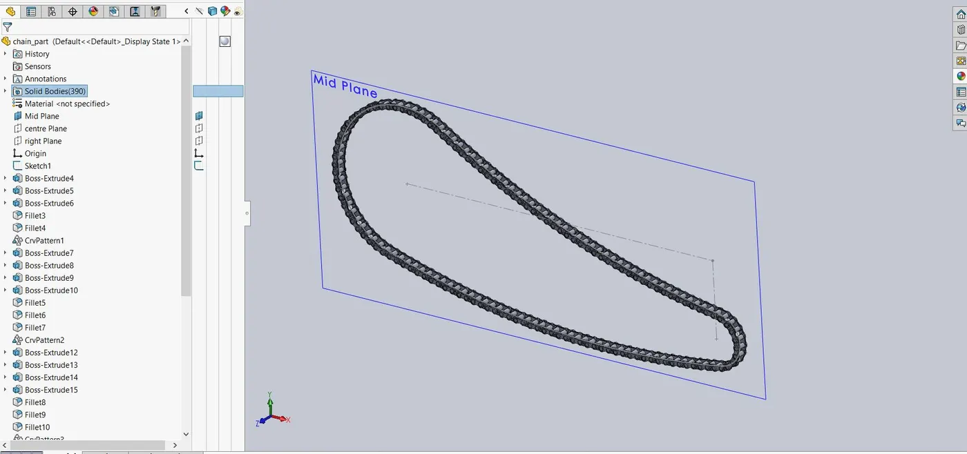
Main Features Used :
- fillet
- extrude
- project curves
it is used to project a sketched curve on the face of the part - curve pattern
it is used to follow the curve while creating multiple copies of the components. - mirror
it is used to create a replica of the existing component on the otheer side using reference axis as exact centre.
OIL TANK :
it is used to store the oil which is acts as lubricant fluid to the engine and transmisison parts.
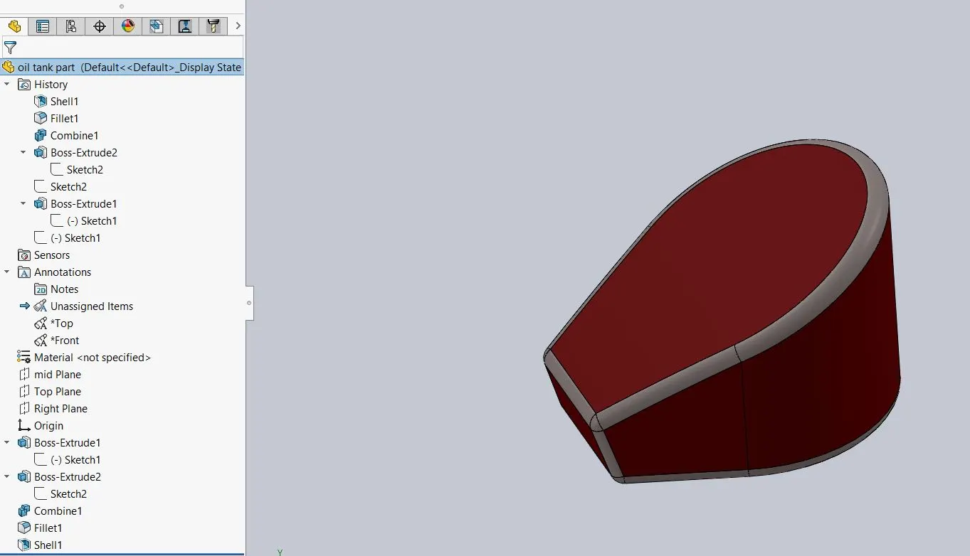
Main features used :
- Boss Extrude
- combine
it is used to combine two extruded parts to become a single part. - fillet
- shell
FOOTPAD PEDALS :
it is used as resting part and as well as support for rider legs while using brake and gear shifting.
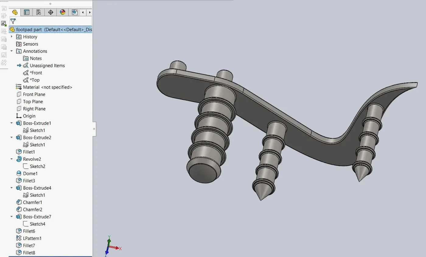
Main features used :
- Boss Extrude
- fillet
- revolve
- dome
- chamfer
- linear pattern
FRONT FORKS :
It is used to connect the front wheel and axle to the frame and it consist of shock absorbers to absorb shocks and handle bar for steering.
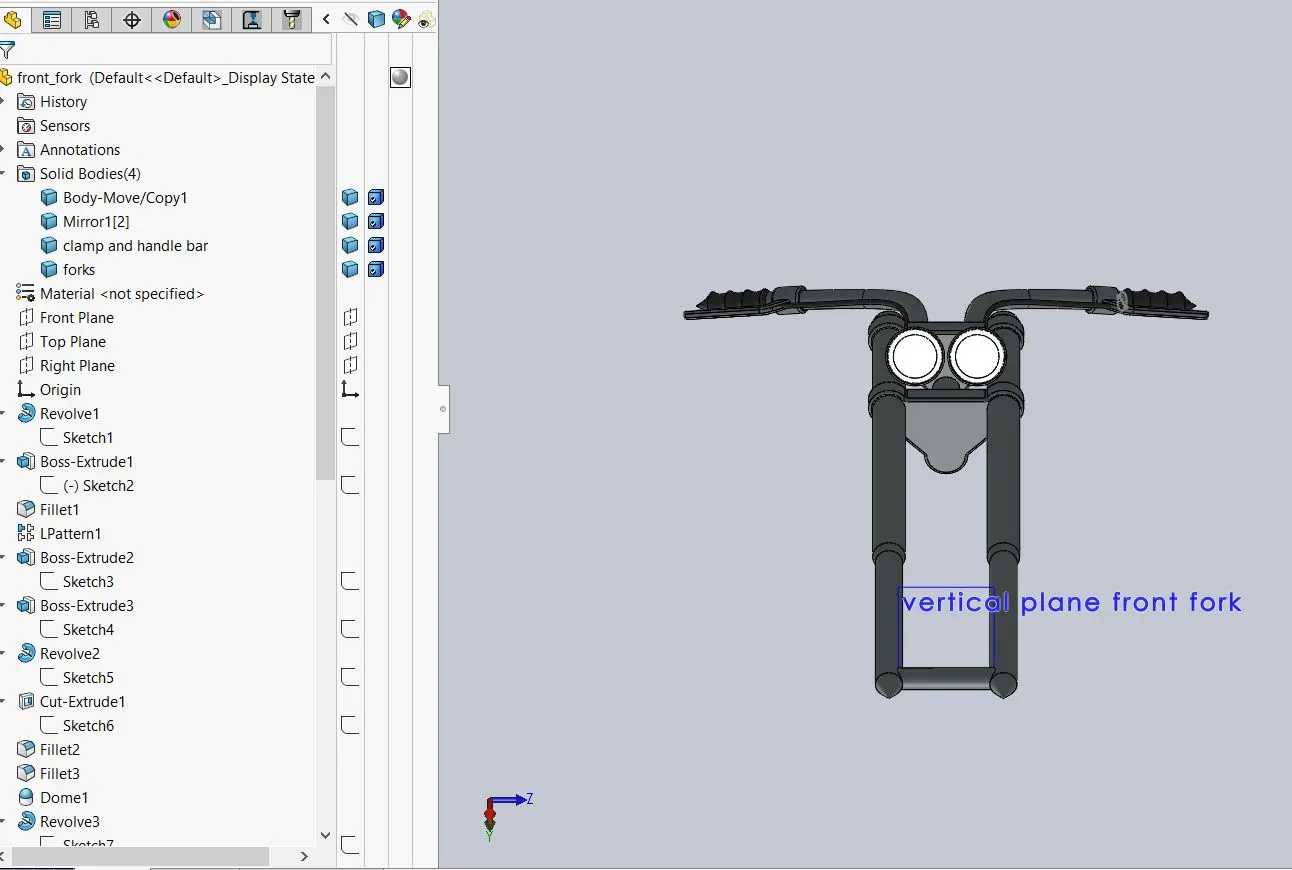
Main features used :
- sketch
- extrude
- trim
- revolve
- split
- refernce plane
- convert entities
It is used to convert the entities into sketch entities. - move/copy body
it is used to move/copy the solid bodies - dome
- mirror
- combine
- project curve
- swept
sweeps a closed profile along a path that creates a solid body.
CHASIS :
It is a frame like structure part which is used to hold and place the other parts of the bike.
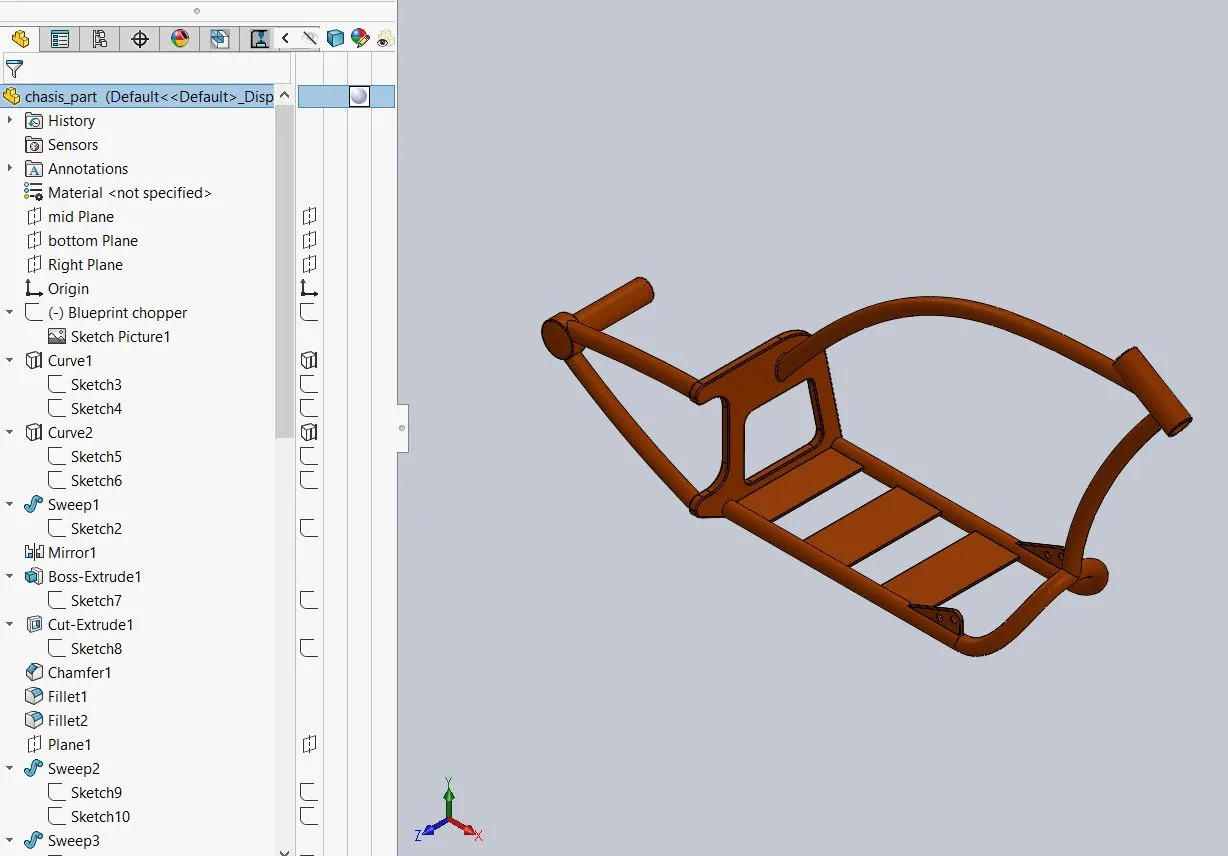
Main features include :
- swept boss
- project curve
- mirror
- extrude boss
- fillet
- cut extrude
- dome
- combine
- chamfer
- split
- revolved boss
- offset
ENGINE :
it is the heart of the bike which creates the heat energy by burning the fuel and air mixture and converts the heat energy into mechanical energy to give motion to the bike.
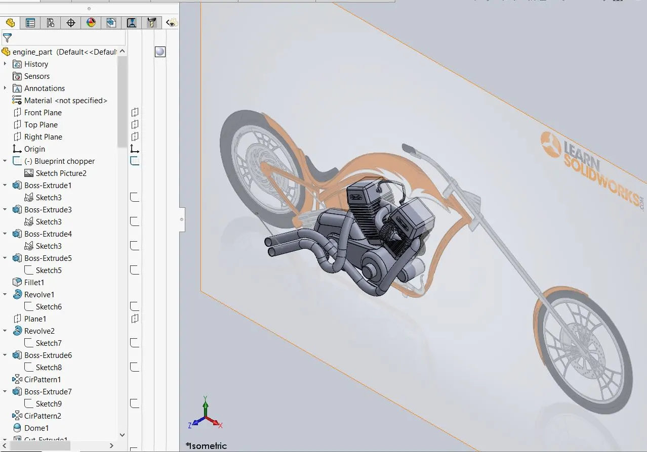
Main features used :
- sketch
- convert entities
- boss extrude
- cut extrude
- trim
- revolve
- offset
- dome
- fillet
- project curve
- swept boss
- mirror
- circular patrern
- split
GAS TANK :
It is used to store the fuel which is required in the engine to burn and generate the heat energy which is later converted into mechanical energy.
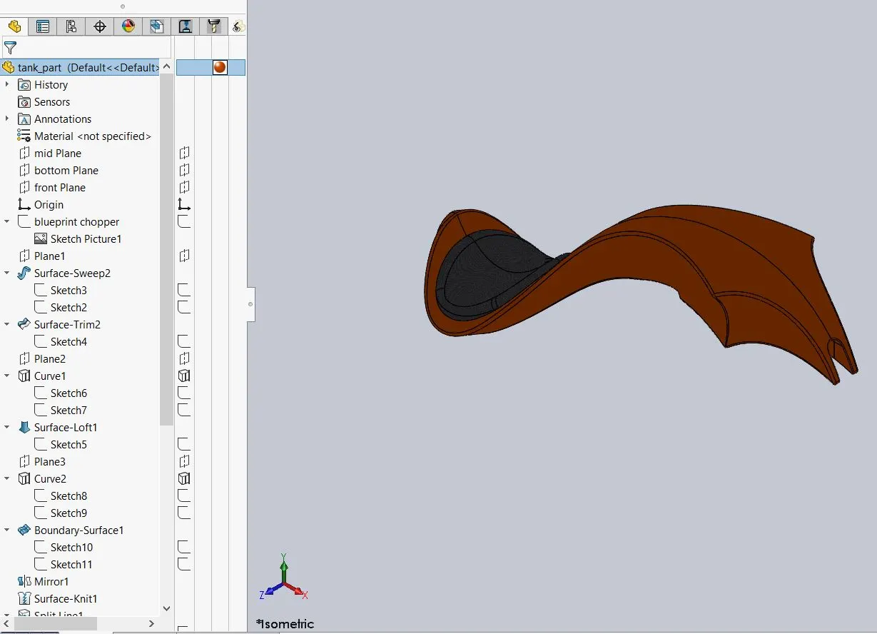
Main features used :
- sketch
- trim
- project curve
- convert entities
- swept boss
- loft surfaces
- fillet
- surface trim
- surface knit
- sweep cut.
ASSEMBLY OF CHOPPER :
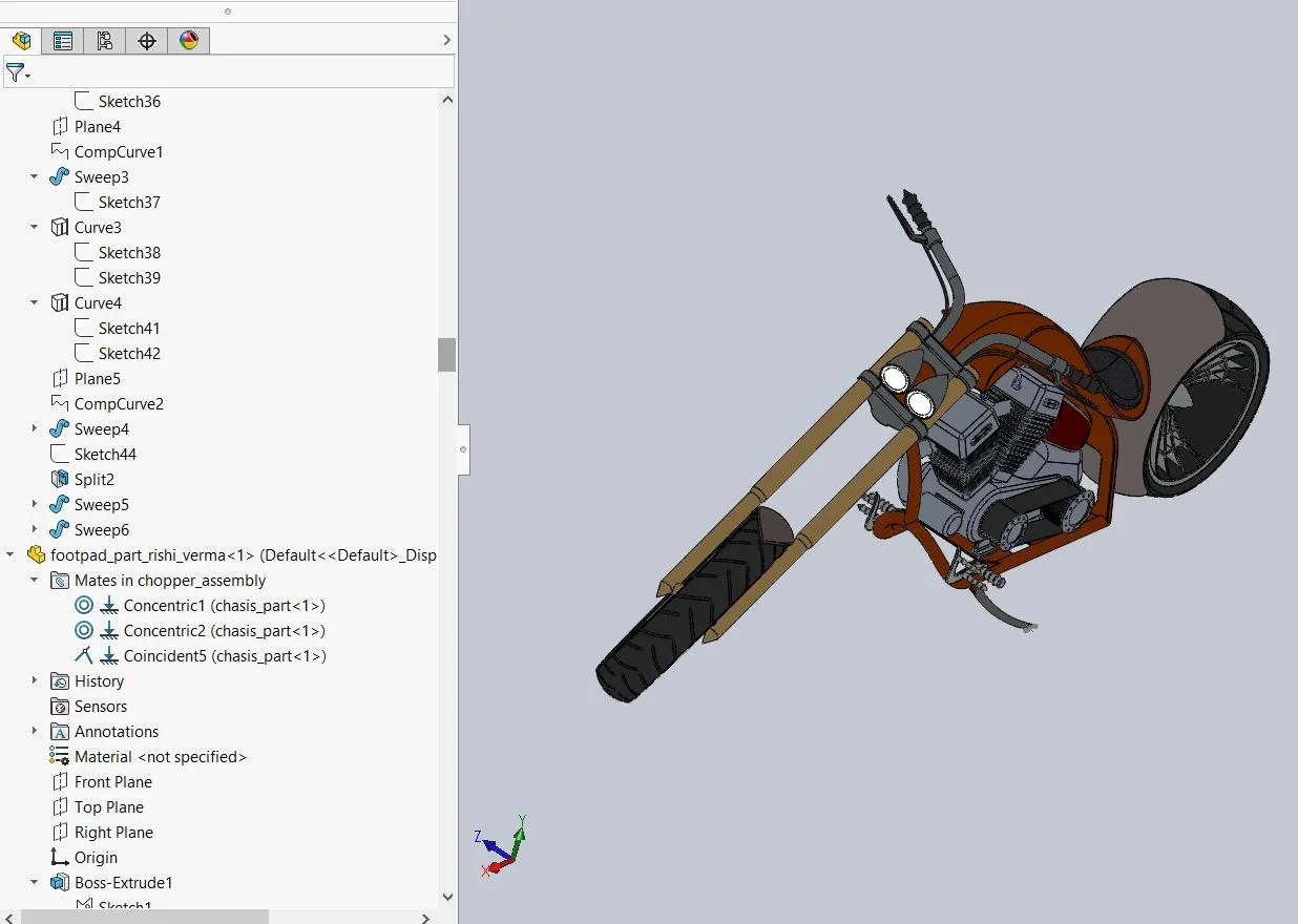
the parts are modeled so far in the solidworks part are saved and import in the assembly tab.
the main features are :
- Insert component
it is used to import or insert the model parts one by one for the assembly and place in the assembly workspace. - Mate
it is used to give mate relation between the parts as per the requirement, relation like concentric, coincient, parallel,etc and advanced mates are used.
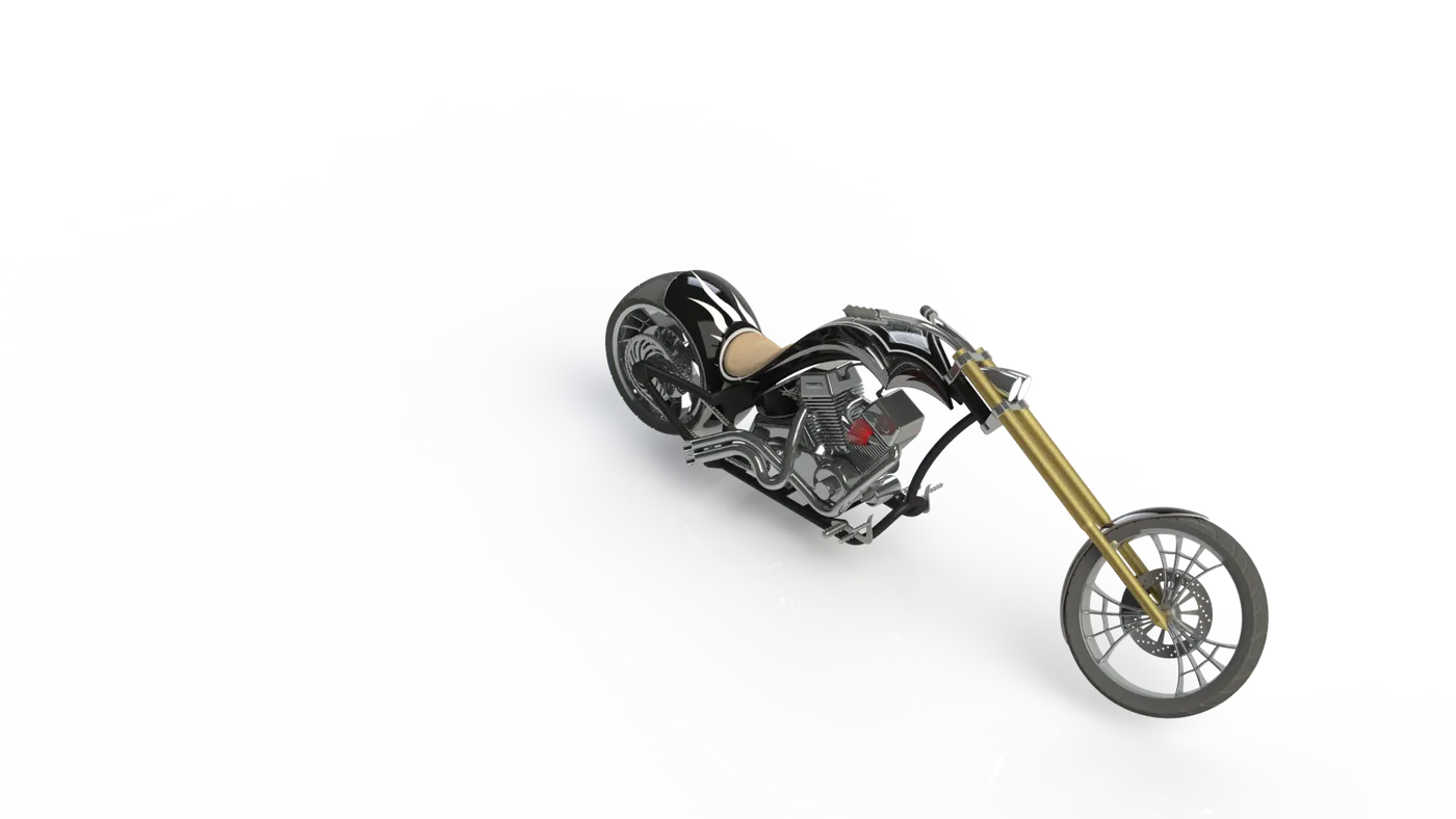
PHOTOVIEW 360 :
TOOLS > ADD INS > PHOTOVIEW 360 to enable the features.
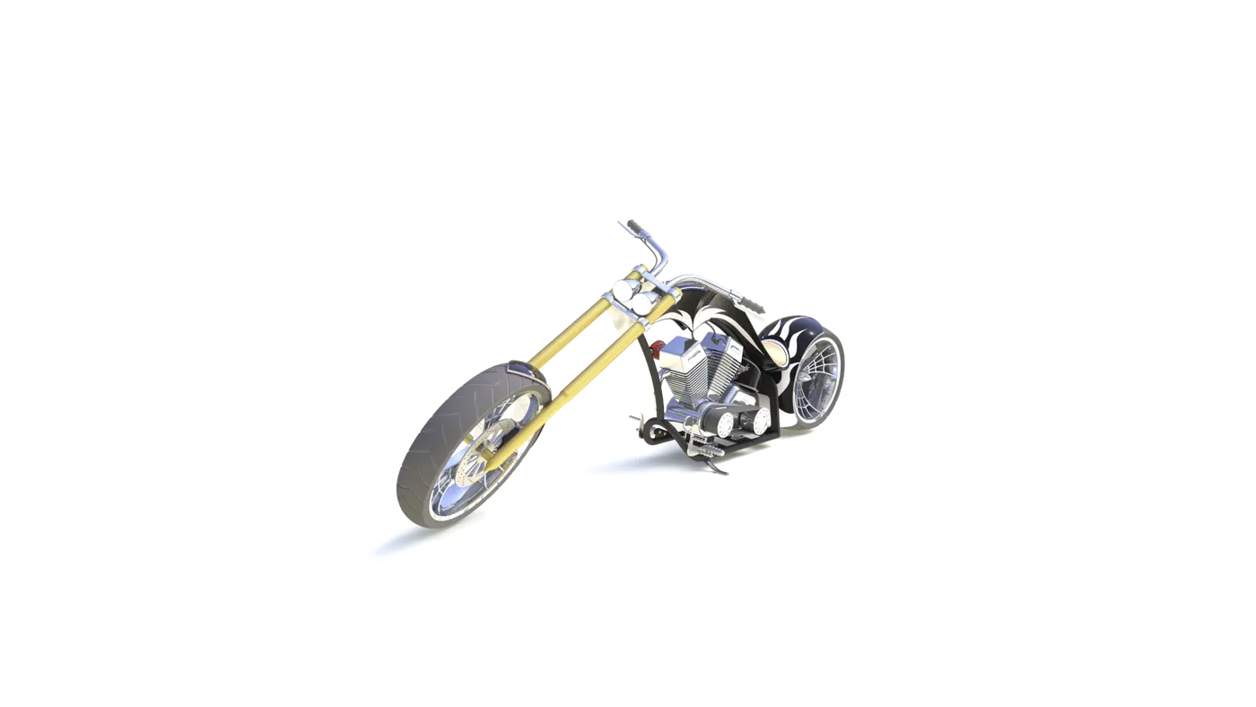
this tool is used for rendering purposes, before the final rendering we set the APPERANCES of bike (like paint,decals,fabric,etc), BACKGROUND SCENES, CAMERAS, LIGHTS, BACKGROUND CONDITIONS, QUALITY OF RENDER,etc.
after setting up the scenes, apperance and quality of output by rendering proceed with final rendering process.
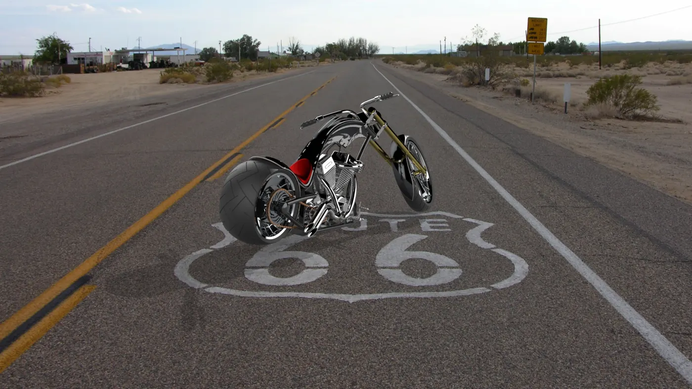
SOLIDWORKS VISUALIZE :
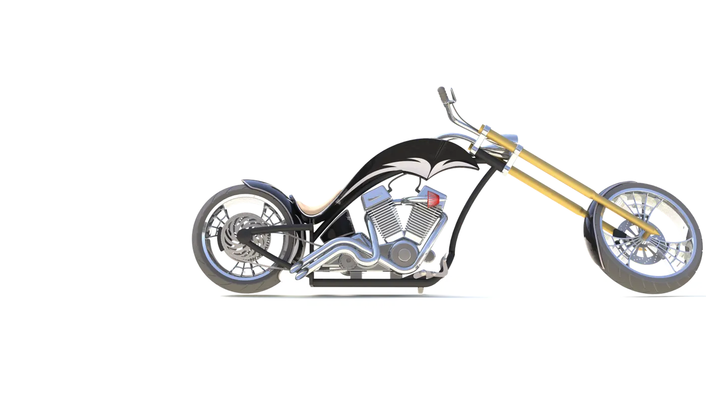
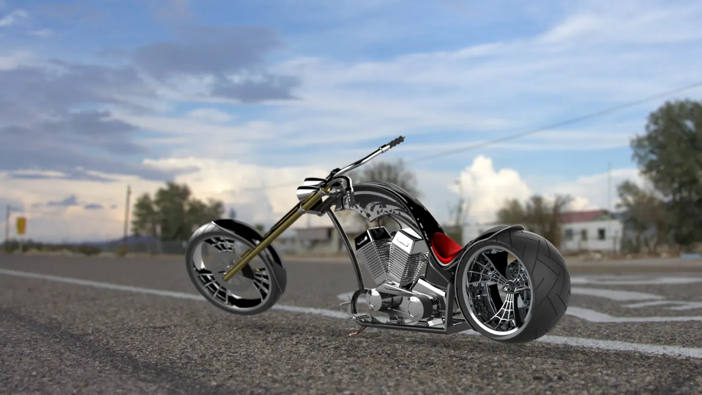
this application is used to get better and realistic kind of rendering Output as like Phtotview 360 we have to set the Appearances, background, scenes, camera,enviornment,etc.after setting up all these proceed for final rendering.
RESULT AND CONCLUSION :
- The parts are designed in Soliworks PART.
- The parts are Assembled in Solidworks assembly.
- The Appearances and Rendering done in Photoview 360 and Solidworks Visualize.