Bird Strike - Project - 2
Aim:
To perform and simulate the non-linear case of Birdstrike in Aero-engine using explicit analysis in LS-Dyna.
Objective:
- the FE model consists of 4 parts,which we need to create seperate (.k) files and similarly create separate (.k) files for material and boundary condition.
- The node number, element number and part number to be changed to unique values.
- For final simulation file, include all the (.k) files created and run the simulation by applying neccesary cards for explicit analysis using mass scaling.
Brief Introduction :
Bird strikes are a major threat to aircraft structures, as a collision with a bird during flight can lead to serious structural damage. Computational methods have been used for more than 30 years for the bird-proof design of such structures, being an efficient tool compared to the expensive physical certification tests with real birds. At the velocities of interest, the bird behaves as a soft body and flows in a fluid-like manner over the target structure, with the high deformations of the spreading material being a major challenge for finite element simulations.
Procedure :
- For this FE model the unit system followed here will be Kg, mm, ms
- The given keyword file consist of four parts i.e Engine casing, Blade, Hub and Blade.
- Separate the given parts by assigning the keywords file. Those parts are distributed and saved .k keyword file.
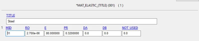
- For a bird, engine casing and hub *MAT_ELASTIC card material is selected and properties are assigned and the input values are shown in below image.
- For blades, *MAT_24_Piecewise_Linear_plasticity card is given with properties of Aluminium, Density-2.713e-6">e−6e-6, Young's Modulus-68.946999, Poisson Ratio-0.3300,
Yield stress-0.0133600, Failure flag-0.2723, and Tangent modulus is given as Load curve ID by plastic strain rate behavior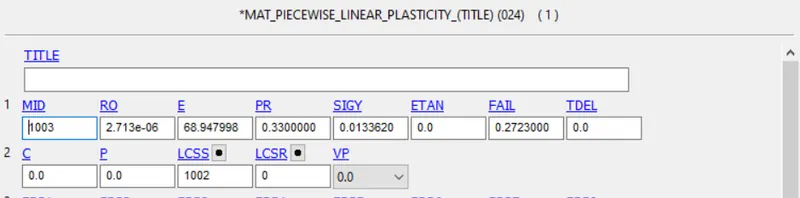
- Section shell is used with thickness of 1mm for shell elements with default integration element formulation.
- section solid is used with the quadratic tetrahedron element with nodal rotations element formulation.
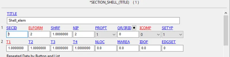
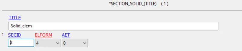
- Now we create a New Main File and INCLUDE card used to import all the different (.k) files which are created for the simulation.
- Following Contact cards are assigned as per the requirement of simulation are :
1) CONTACT_TIED_NODES_TO_SURFACE is used to tied the surfaces with the blade as a slave and hub as master.
2) CONTACT_AUTOMATIC_SURFACE_TO_SURFACE is used as the bird as a slave and blade as a master.
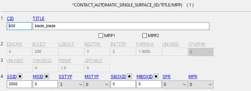
3) CONTACT_AUTOMATIC_SINGLE_SURFACE is used to check the penetration between the blades once the bird strikes.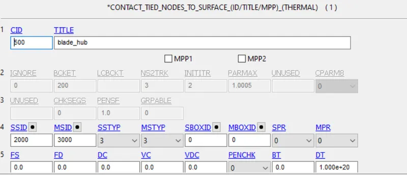

- Boundary conditions :
1)Though the turbine engine case supposed to be fixed at the airplane wing. It has to be constrained in all the directions i.e, Translation and Rotation.
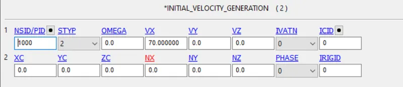
2) The velocity of the bird travels towards turbines is 70 mm/ms along the X-axis translative direction.
3) The angular velocity of the blades is roughly Considering and convert it to radiant. From which angular velocity OMEGA=0.5 rad/ms, NX=1 (x-direction cosine).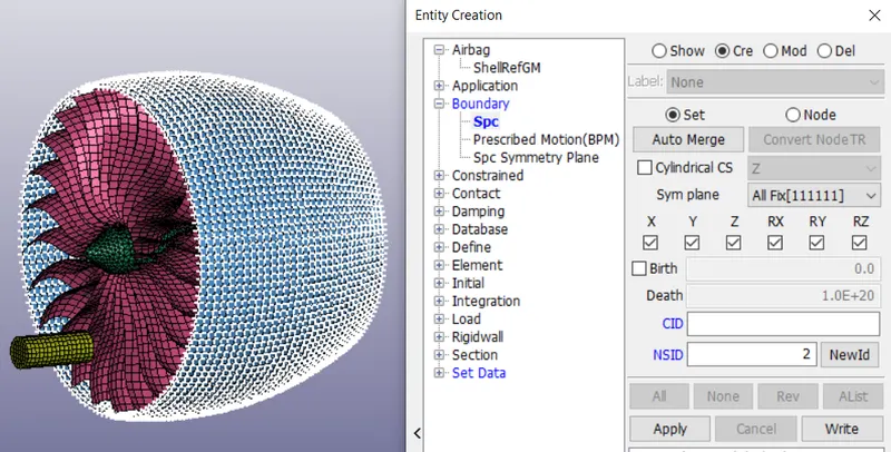
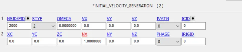
- The simulation running time is set to be 2 ms.
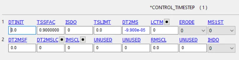
- For mass scaling after multiple iterations, the time-step card is given with a DT2MS -9.900e-05 and TSSFAC 0.9

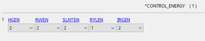
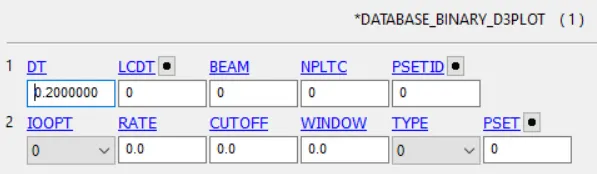
- Database D3PLOT, GLSTAT and MATSUM cards are assigned to write the output data in interval of 0.2ms.
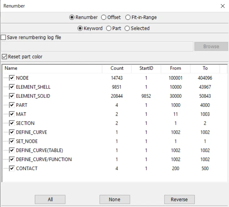
- Renumber of the PARTS, ELEMENTS and NODES are done.
Result :
It is clearly observed from the simulation, deformation of the blades after hit by bird at a velocity of 70 mm/ms. The simulation is provided with the link below.
https://youtu.be/PL4AJ2WtWSI
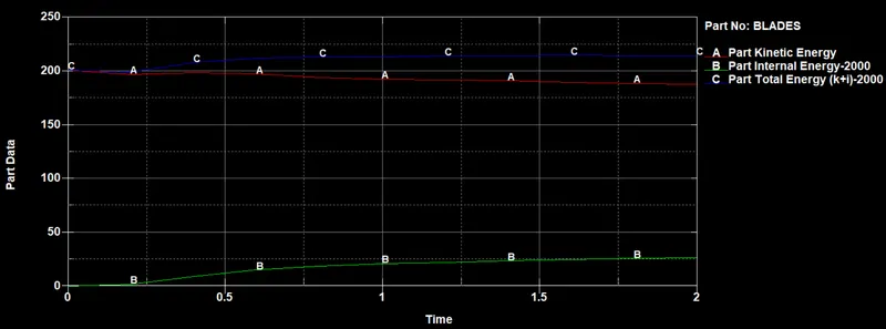
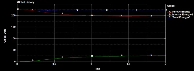
In this Explicit Analysis, when the bird hits the blade at a velocity of 30kmph. The Internal energy increases and kinetic energy decreases due to the impact on the blades.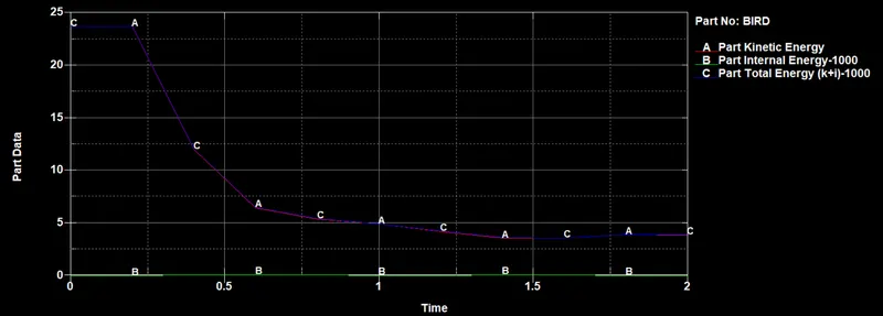
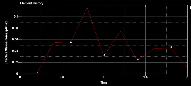
Effective Stresses
Element selected from point of contact with blade from Bird part
Element selected from point of contact with blade from Blades part
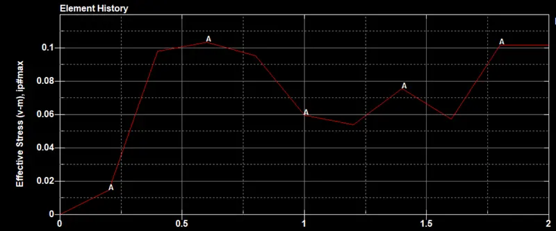
Hence we can notice that the plot satisfies the law of conservation of energy and the difference in energy flow between Bird and Blades after crash.
Conclusion
- All the subsystems were created and included with the Main_Include file. The simulation is assigned and performed using the mass scaling factor
- Transient-non linear bird strike application understands and done using LS-Dyna. The contour plots and global results are observed to understand the energy flow in the simulation.