Week - 5 - Modelling Spotwelds
AIM : Model SPOTWELD for the given parts assembly and do the CRASH TEST using LS-DYNA.
OBJECTIVE :
- Import the assembly parts keyword file in Ls-Prepost.
- 1)Create BEAM elements SPOTWELD. 2) Create SOLID elements SPOTWELD.
- Assign the keyword cards as per the requirement for CRASH TEST simulation and check for MODEL ERRORS.
- Save the file and run the file in LS manager for the analysis.
- Open the output DATABASE files in Ls-Prepost for results.
- compare the results of both BEAM and SOLID elements.
PROCEDURE :
- First step is to import the keyword file provided in the ls-prepost.
- Create the Beam element spotwelds for the parts.
- In MESH > ELEM GEN, option is used for the creation of BEAM elements for spotwelds. In this case we are using 5 spotwelds (1 on right side , 1 on left side and 3 on top).
- similarly for SOLID ELEMENTS,In MESH > ELEM EDIT> HEXA is used for the creation of SOLID element for spotwelds. In this case we are using 5 spotwelds (1 on right side , 1 on left side and 3 on top).
- on is used for the creation of BEAM elements for spotwelds. In this case we are using 5 spotwelds (1 on right side , 1 on left side and 3 on top).
- after that we have to assign the keyword cards as per the requirement of Crash test simulation.
- In the below images you can see the following cards we used :
FOR BEAM ELEMENTS USED FOR SPOTWELDS (units taken in g/mm/ms )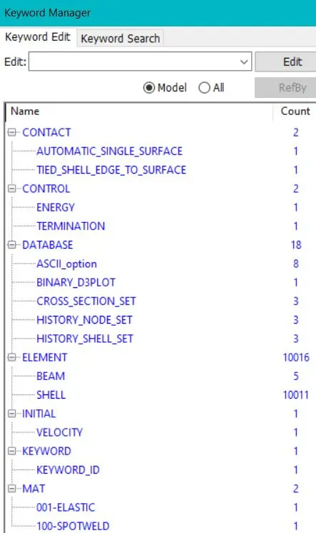
- In Contact cards we are using 1) Automatic_single_surface by providing Part Set ID as slaves.
2) Tied_shell_edge_to_surface by providing Spotwelds as Slaves and Parts as masters. - In Control cards we are using 1) Energy card for Hourglass energy and sliding interface (HGEN=2 , SLNTEN=2)
2) Termination card is used to define the time of end of the Crash Test.(time given 5 milisecond) - In DATABASE cards we are using 1) ASCII (GLSTAT, NODOUT, RCFORC, SECFORC, SLEOUT, ELOUT) to write the test data in time spam of (0.1 milisecond).
2) BINARY D3 PLOT is used as compulsary card for the output data to be stored as in simulation to write the test data given time spam is (0.1 milisecond).
3) CROSS SECTION SET is used to store the test values at the Cross section areas on the parts.(manully providing the cross section areas by providing shell/node sets)
4) HISTORY NODE SET is used to store the test values for the particular node sets.
5) HISTORY SHELL SET is used to store the test values for the particulat shell elements sets. - In ELEMENTS cards 1) BEAM elements we are created.
2) SHELL elements are provided with keyword file
(note : this cards shows the file contains the type of elements and number of elements ) - INITIAL card is used to give VELOCITY to the parts, In this case we are giving velocity of 13.88 mm/ms.(i.e 50kmph) in X-direction as our Rigid wall used is in (-x) direction to the first node/element of parts.
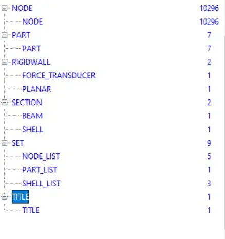
- MAT (material) cards used are 1) 001 ELASTIC - as to define the material for the assembly parts.
2) 100 SPOTWELD - as to define the material for spotwelds.(by using this material card we have to consider beam element of type 9 and to
solid element type 1) (TFAIL time failure given for spotweld to fail is 2ms)
(note : material properties used to define the material card is of STEEL, which properties are rho=7.75*10^-3g/mm, E=180*10^3 MPa, Poison ratio= 0.30, SIG Y= 314Mpa) - RIGID WALL card is used to create a PLANAR rigid wall for carsh test. the wall is placed in 15mm (-x) direction to the first node/ element of the assembly parts.
- SECTION card used 1) BEAM is used to provide the Element fromulation and thickness to the beam elements created for spotwelds (In this caseas per the material card used ELFORM=9 and T=5mm).
2) SHELL is used to provide the Element fromulation and thickness to the shell elements (in this case ELFORM=16( Fully integrated shell element) and T=2mm) - SET card used 1) NODE_LIST is used to create set of selected nodes.
2) PART_LIST is used to create a set of selected parts.
3)SHELL_LIST is used to create a set of selected shell elements. - In the below image you can see the TREE of following cards applied to the assembly parts.
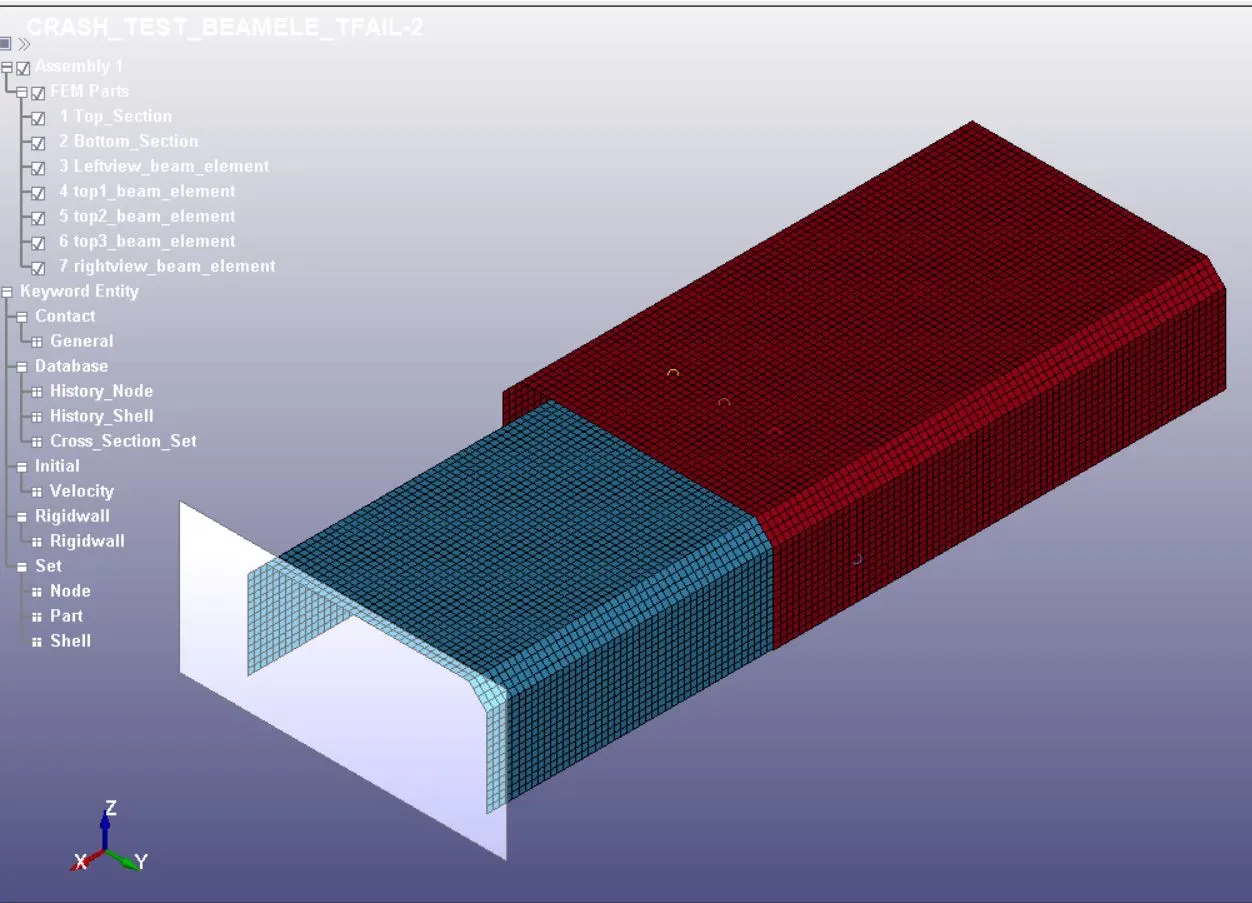
- now we save the file with (.k)extension and run it in LS manager .
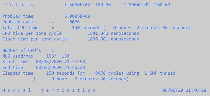
- In the below image you can see the SPOTWELD is failing as per the given time of fail and the time taken to complete the test to run.

FOR SOLID ELEMENTS USED FOR SPOTWELDS (units taken in g/mm/ms )
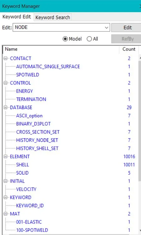
- In Contact cards we are using 1) Automatic_single_surface by providing Part Set ID as slaves.
2) SPOTWELD by providing SOLID ELE as Slaves and Parts as masters. - In Control cards we are using 1) Energy card for Hourglass energy and sliding interface (HGEN=2 , SLNTEN=2)
2) Termination card is used to define the time of end of the Crash Test.(time given 5 milisecond) - In DATABASE cards we are using 1) ASCII (GLSTAT, NODOUT, RCFORC, SECFORC, SLEOUT, ELOUT) to write the test data in time spam of (0.1 milisecond).
2) BINARY D3 PLOT is used as compulsary card for the output data to be stored as in simulation to write the test data given time spam is (0.1 milisecond).
3) CROSS SECTION SET is used to store the test values at the Cross section areas on the parts.(manully providing the cross section areas by providing shell/node sets)
4) HISTORY NODE SET is used to store the test values for the particular node sets.
5) HISTORY SHELL SET is used to store the test values for the particulat shell elements sets. - In ELEMENTS cards 1) SOLID elements we are created.
2) SHELL elements are provided with keyword file
(note : this cards shows the file contains the type of elements and number of elements ) - INITIAL card is used to give VELOCITY to the parts, In this case we are giving velocity of 13.88 mm/ms.(i.e 50kmph) in X-direction as our Rigid wall used is in (-x) direction to the first node/element of parts.
- MAT (material) cards used are 1) 001 ELASTIC - as to define the material for the assembly parts.
2) 100 SPOTWELD - as to define the material for spotwelds.(by using this material card we have to consider beam element of type 9 and to
solid element type 1) (TFAIL time failure given for spotweld to fail is 2ms)
(note : material properties used to define the material card is of STEEL, which properties are rho=7.75*10^-3g/mm, E=180*10^3 MPa, Poison ratio= 0.30, SIG Y= 314Mpa) - RIGID WALL card is used to create a PLANAR rigid wall for carsh test. the wall is placed in 15mm (-x) direction to the first node/ element of the assembly parts.
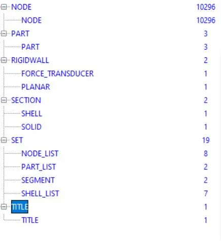
- SECTION card used 1) SOLID used to provide the Element fromulation and thickness to the SOLID element created for spotwelds (In this caseas per the material card used ELFORM=1).
2) SHELL is used to provide the Element fromulation and thickness to the shell elements (in this case ELFORM=16( Fully integrated shell element) and T=2mm) - SET card used 1) NODE_LIST is used to create set of selected nodes.
2) PART_LIST is used to create a set of selected parts.
3)SHELL_LIST is used to create a set of selected shell elements. - In the below image you can see the TREE of following cards applied to the assembly parts.
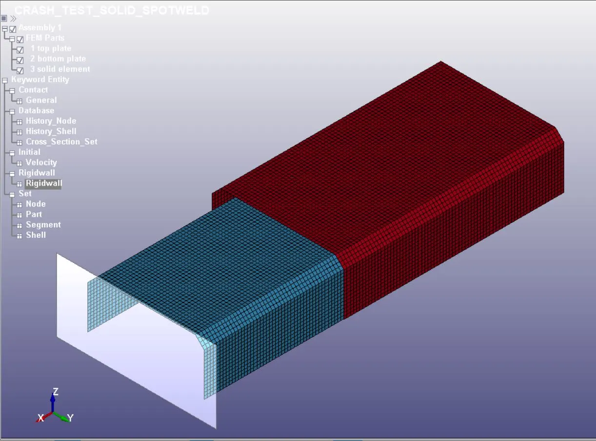
- now we save the file with (.k) extension and run the file for test in LS manager.
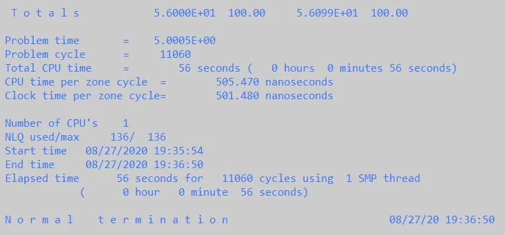
- In the below image you can see the spotwelds are failing as per the given TFAIL and time taken for test to run.

RESULTS :
As per the given task the CRASH test is done by creating SPOTWELDS for ASSEMBLY PARTS usign both BEAM and SOLID ELEMENTS.
the saved files are shared using link below for further process and reference
https://1drv.ms/u/s!AnGsOah9scM2gQCBAD5HvPfwnUyA?e=gMEfN1
the results are shown in the form of animation and the graph plotted values.
https://www.youtube.com/watch?v=RNGATqCbU2U
https://www.youtube.com/watch?v=vr83WyX8A30
GRAPH PLOTTED VALUES
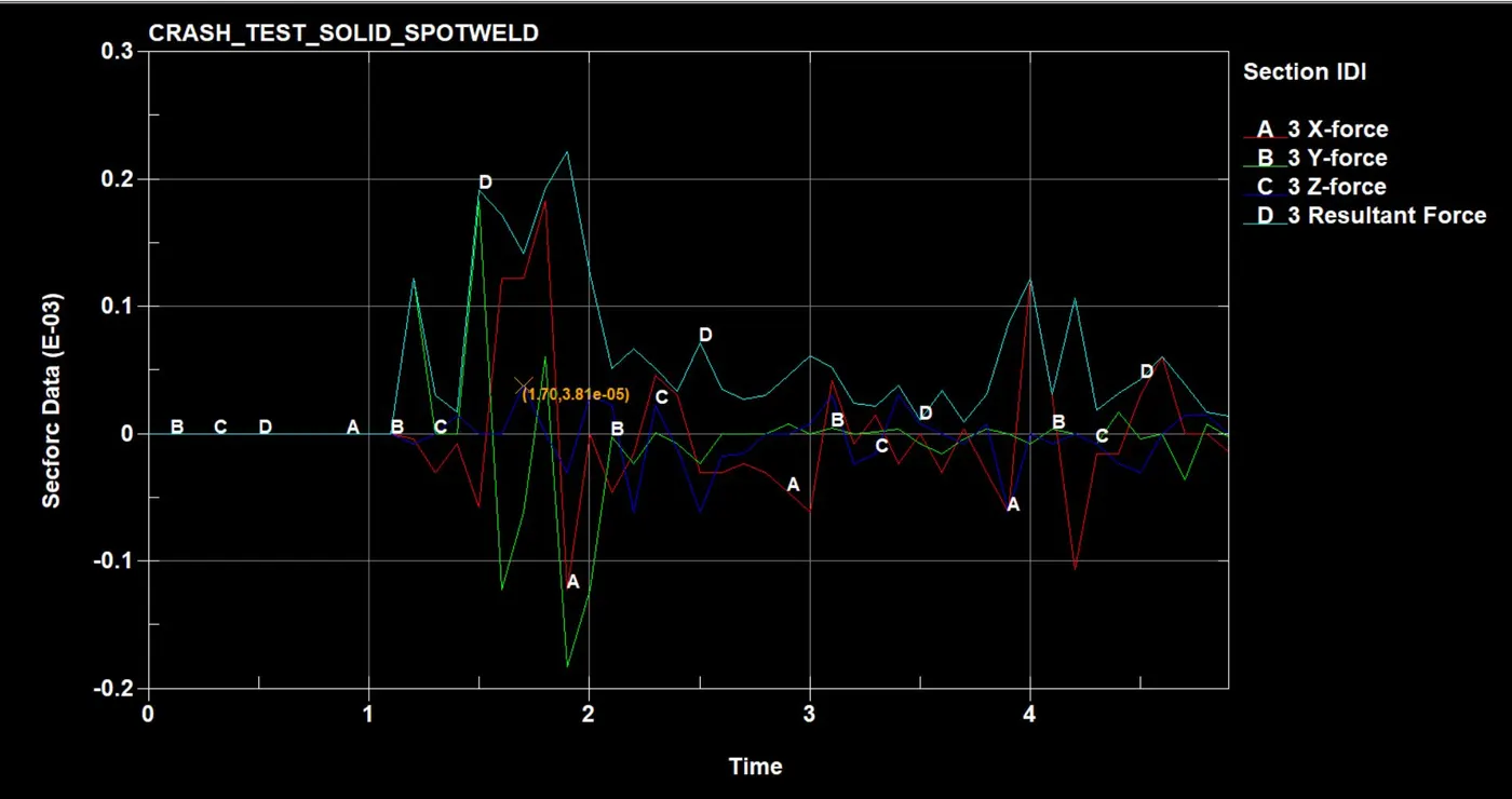
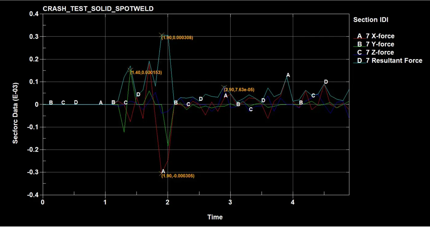
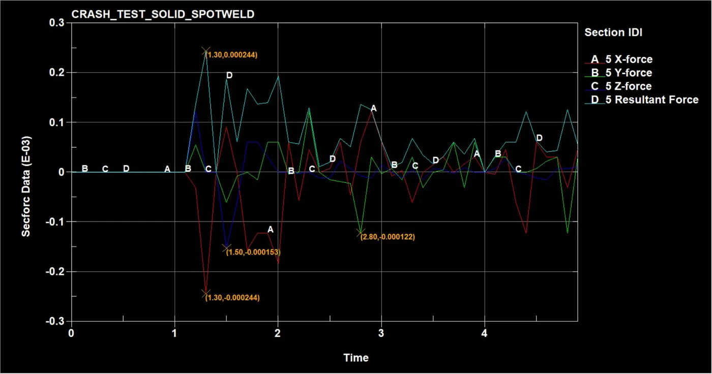
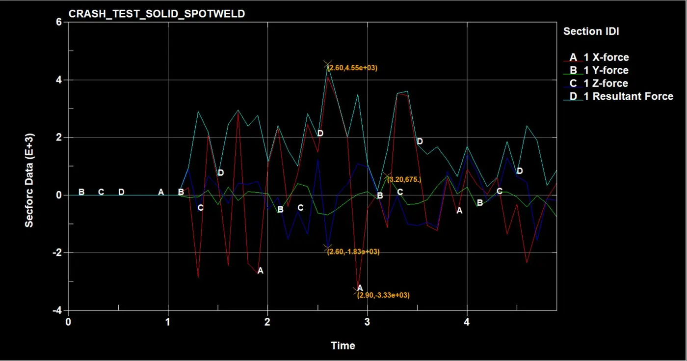
SECTION FORCE
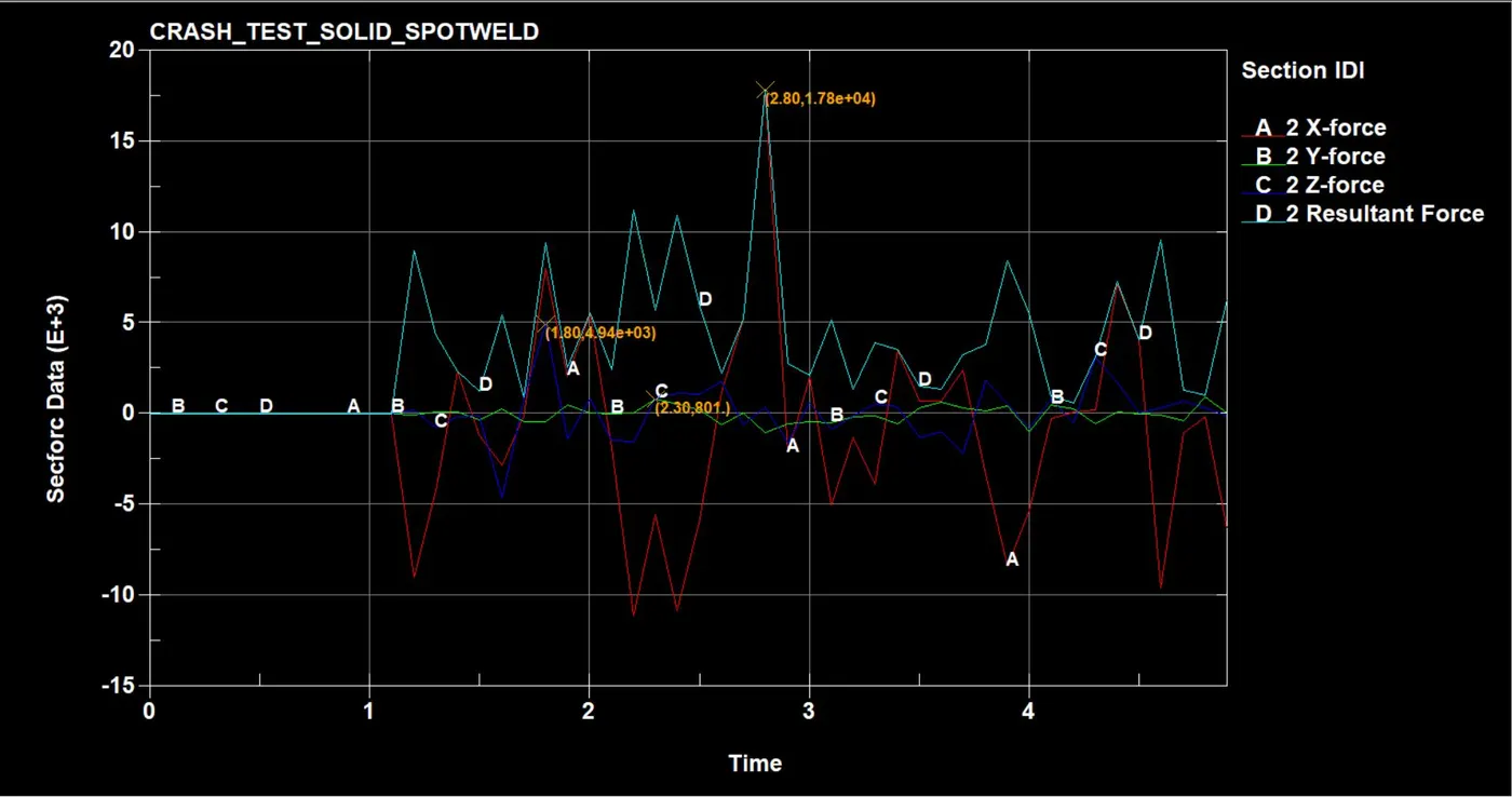
RIGHT SPOTWELD SOLID ELEEMNT
LEFT SPOTWELD SOLID ELEMENT
TOP MID SPOTWELD SOLID ELEMENT
TOP PART MIDDLE CROSS SECTION SOLID ELEMENT SPOTWELD
BOTTOM PART MIDDLE CROSS SECTION SOLID ELEMENT SPOTWELD
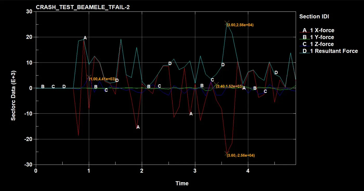
BEAM ELEMENT SPOTWELD CROSS SECTION
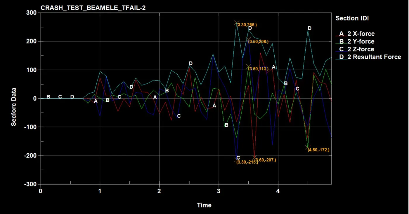
BEAM ELEMENT SPOTWELD TOP PART CROSS SECTION
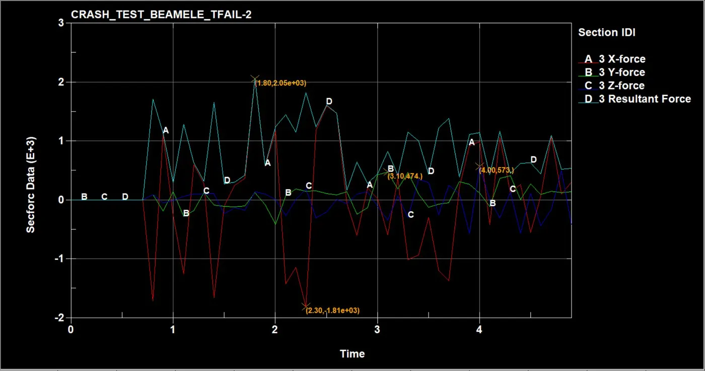
BEAM ELEMENT SPOTWELD BOTTOM PART CROSS SECTION
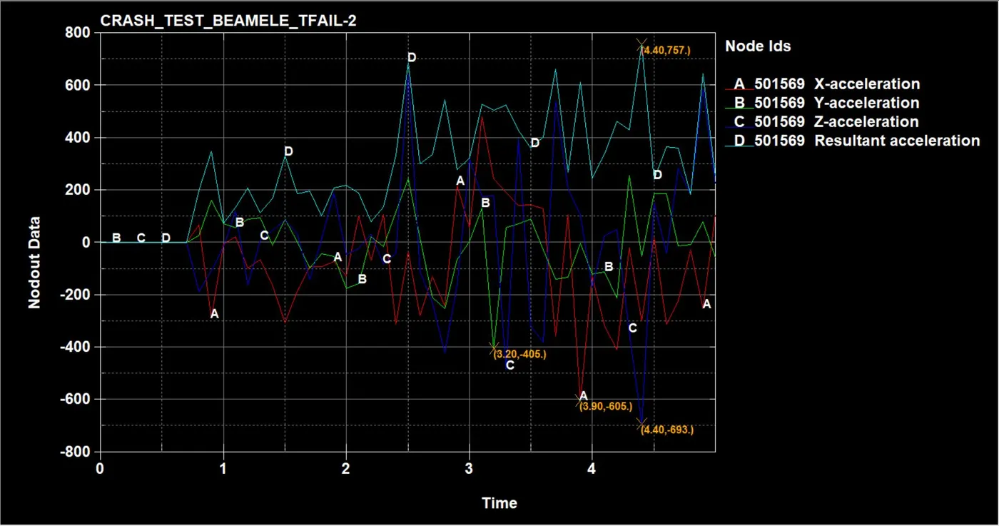
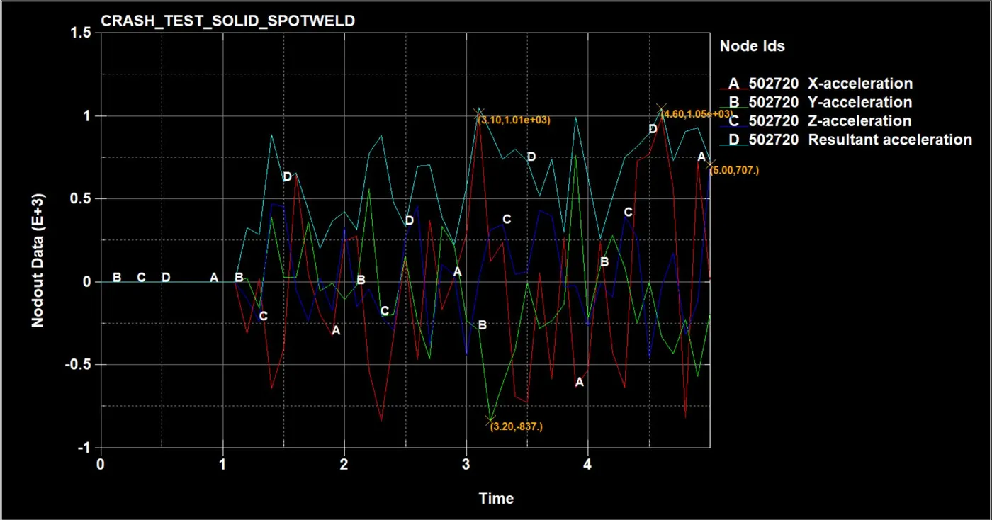
ACCELERATION DIFFERENCE
BEAM ELEMENT SPOTWELD ACCELERATION VALUES OF TOP MIDDLE NODE
SOLID ELEMENT SPOTWELD ACCELERATION VALUES FOR TOP MID NODE
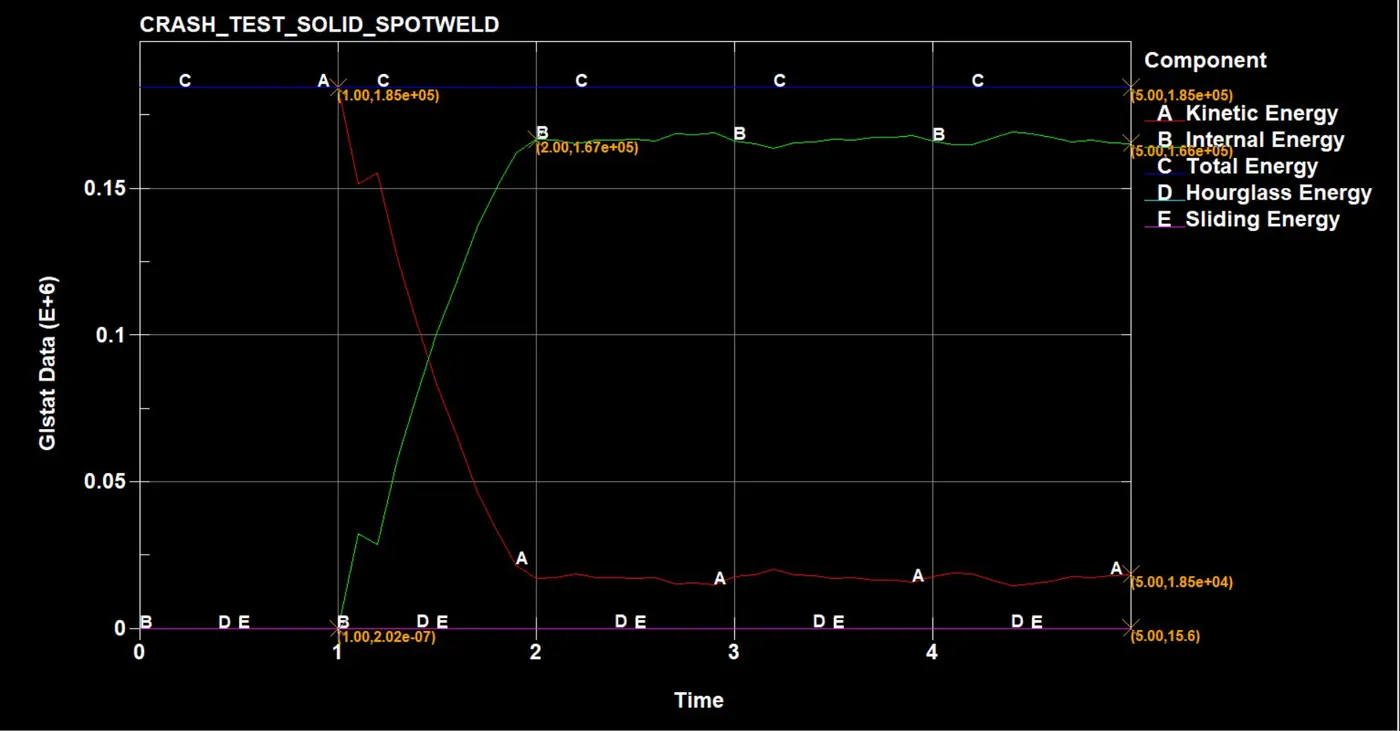
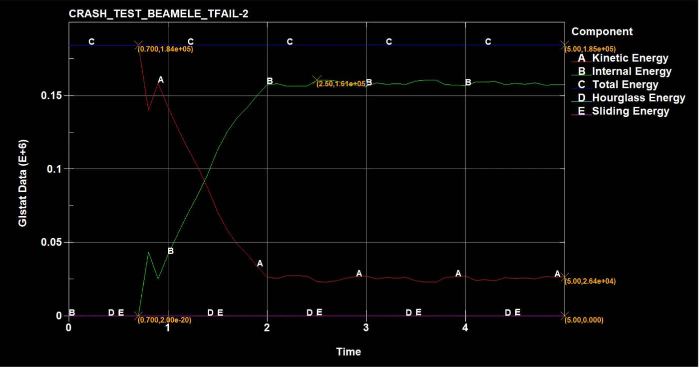
GLSTAT ENERGIES DIFFERENCE
DIRECTIONAL STRESS AT THE MIDDLE SHELL ELEMENT
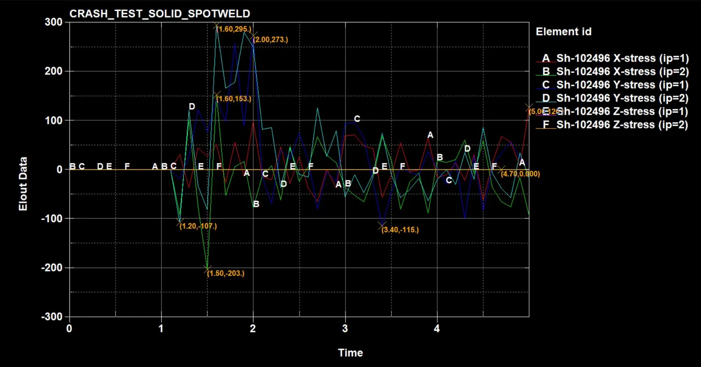
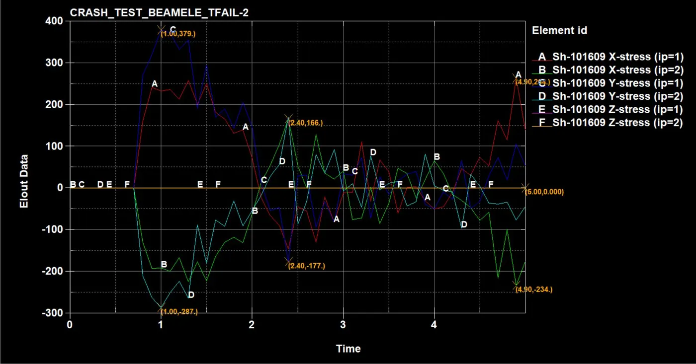
DIRECTIONAL STRAIN AT MIDDLE ELEMENT
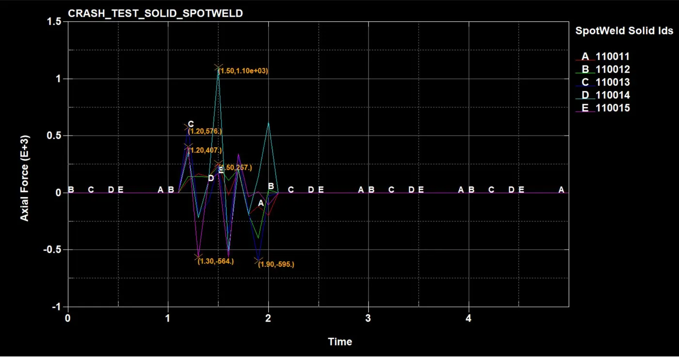
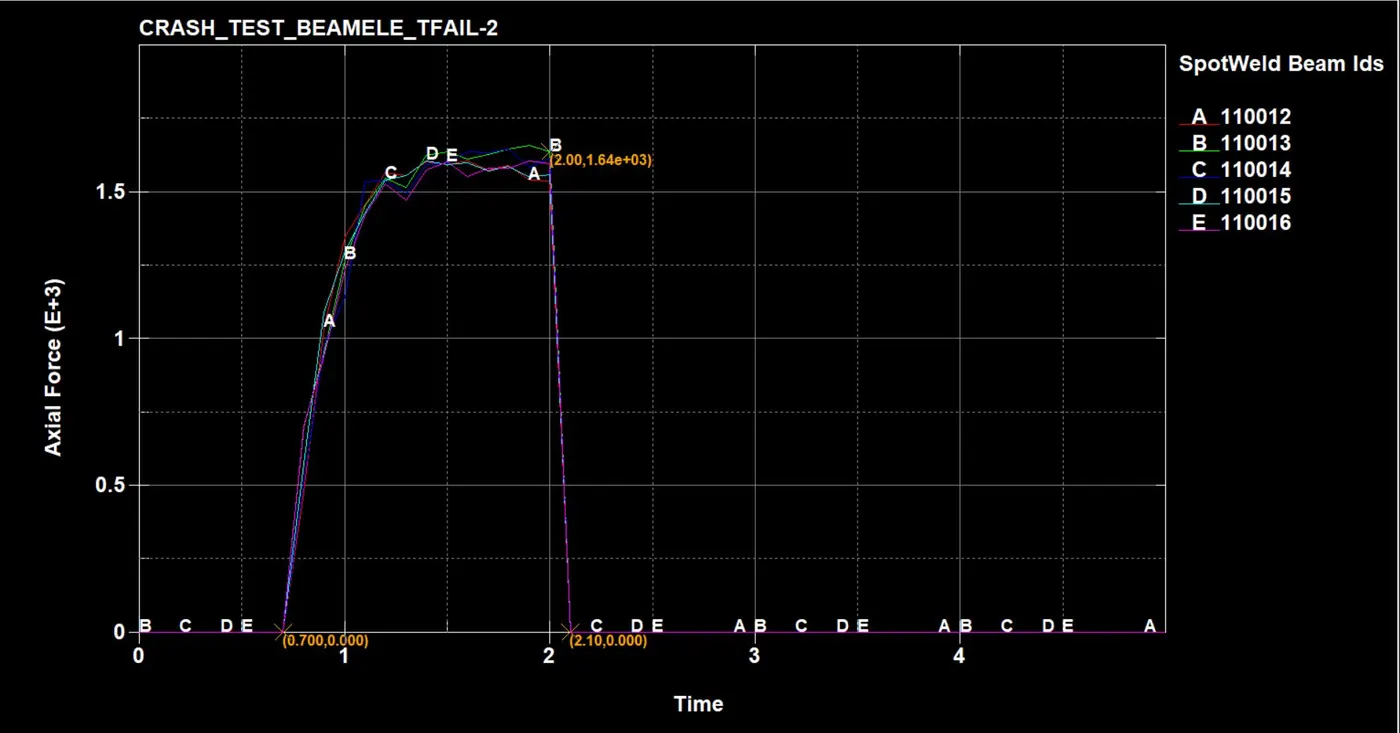
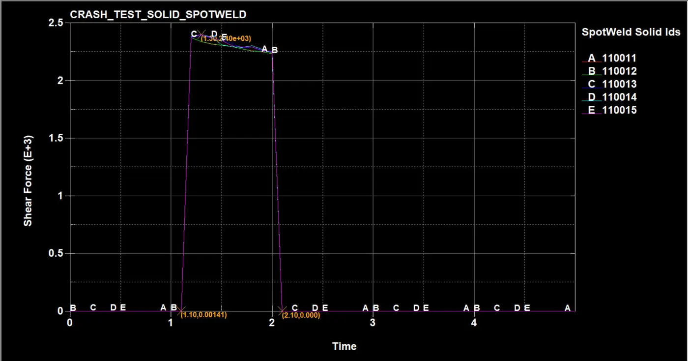
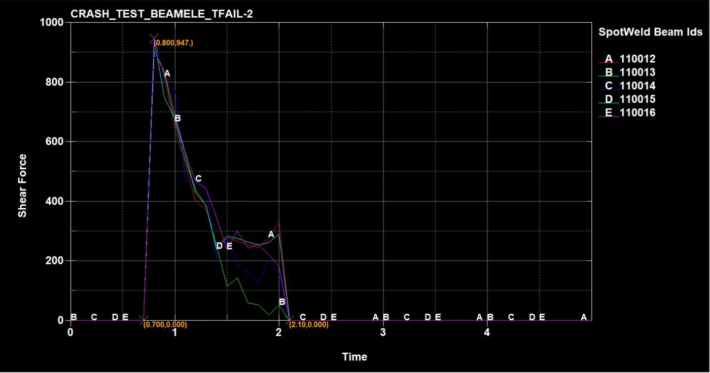
AXIAL FROCE AND SHEAR FORCE DIFFERENCE BETWEEN BEAM ELEMENT AND SOLID ELEMENT SPOTWELDS
SOLID ELEMENT SPOTWELDS
BEAM ELEMENT SPOTWELDS
SOLID ELEMENT SPOTWELDS
BEAM ELEMENT SPOTWELDS
CONCLUSION :
As per comparing the results of both BEAM ELEMENT AND SOLID ELEMENT for
| BEAM | ELEMENT | SOLID | ELEMENT | |||
| TIME | 0.8 | 2 | 1.30 | 1.50 | 2.00 | |
| AXIAL FORCE | 1.64e+03N | 1.10e+03N | ||||
| SHEAR FORCE | 947N | 331N | 2.40e+03N | 2.24e+03N |
as you can see the axial force is high in the beam element is because the thickness is provided for the beam element is 5mm which is more than the thickness of the solid element as compare and in shear force values you can see the beam element spotwelds holds max force only at the time of crash collison with wall after that i gradually decreasing before the time of fail at 2ms but in the solid element spotwelds you can easily see that it holds max force more than beam element spotwelds at the time of crash collison and at time failure of element even after its thickness is less.
so as per the results it is prefferable that using solid element spotweld for better stiffness and proper presentation of spotweld.